EP0035943B1 - Magnetic head with variable track-width for writing or reading magnetic data - Google Patents
Magnetic head with variable track-width for writing or reading magnetic data Download PDFInfo
- Publication number
- EP0035943B1 EP0035943B1 EP81400351A EP81400351A EP0035943B1 EP 0035943 B1 EP0035943 B1 EP 0035943B1 EP 81400351 A EP81400351 A EP 81400351A EP 81400351 A EP81400351 A EP 81400351A EP 0035943 B1 EP0035943 B1 EP 0035943B1
- Authority
- EP
- European Patent Office
- Prior art keywords
- magnetic
- width
- recording
- reading
- gap
- Prior art date
- Legal status (The legal status is an assumption and is not a legal conclusion. Google has not performed a legal analysis and makes no representation as to the accuracy of the status listed.)
- Expired
Links
Images


Classifications
-
- G—PHYSICS
- G11—INFORMATION STORAGE
- G11B—INFORMATION STORAGE BASED ON RELATIVE MOVEMENT BETWEEN RECORD CARRIER AND TRANSDUCER
- G11B5/00—Recording by magnetisation or demagnetisation of a record carrier; Reproducing by magnetic means; Record carriers therefor
- G11B5/127—Structure or manufacture of heads, e.g. inductive
- G11B5/187—Structure or manufacture of the surface of the head in physical contact with, or immediately adjacent to the recording medium; Pole pieces; Gap features
- G11B5/245—Structure or manufacture of the surface of the head in physical contact with, or immediately adjacent to the recording medium; Pole pieces; Gap features comprising means for controlling the reluctance of the magnetic circuit in a head with single gap, for co-operation with one track
- G11B5/2452—Structure or manufacture of the surface of the head in physical contact with, or immediately adjacent to the recording medium; Pole pieces; Gap features comprising means for controlling the reluctance of the magnetic circuit in a head with single gap, for co-operation with one track where the dimensions of the effective gap are controlled
Definitions
- the present invention relates to the field of magnetic recording, and relates to electromagnetic transducers usually referred to as "heads". Such transducers cooperate with a mobile magnetizable support whose local variations in the magnetic state represent the actual recording, and have the function of converting these variations into an exploitable electrical signal available at their terminals. Symmetrically, the application of an electrical signal to their terminals determines a variable magnetization in the mobile magnetizable support which is scrolled in front of these transducers.
- the width of the air gap and the material of which the magnetic circuit is made are not the same if we want to optimize the result of each operation. This is the case, for example, in the field of electroacoustics.
- the recording air gap is simply chosen to have, transversely, a length three times the length of the reading air gap.
- This magnetic data recording and reading head comprises a magnetic circuit (1) provided with an air gap (10) made of non-magnetic material with a thickness of between 2 and 100 microns delimited by two rectangular polar faces arranged facing each other. screw, the first being of width L 2 greater than the width L, of the second which comprises two plates carrying with it in contact with the air gap a width L 2 , as well as electrical means (2) and (3) for the respective application and extraction on a mobile medium of recording and reading signals in cooperation with the air gap 10.
- the plates are lateral plates produced integrally with the second part polar on a thickness less than or equal to 500 microns and giving with it a rectangular contour equal to that of the first pole piece, so as to allow a recording of width of the order of L 2 and a reading of width of the o rdre de L, on the mobile support.
- a pole piece in one piece of width identical to the widest pole piece over a small thickness and then of reduced width allows to benefit from the advantages of magnetic heads with pole pieces of different widths while avoiding the disadvantages mentioned above.
- its final magnetic state depends only, all other things being equal, on the field which prevails at the exit edge of the air gap, which field varies with the frequency of the signal to be recorded and that of the high frequency polarization signal characteristic of magnetic recording.
- the electrical signal collected at the terminals of the windings depends on the width itself of the air gap, the maximum frequency which it is possible to read before cancellation of the signal corresponds to the case where the reading gap has a width equal to the corresponding wavelength recorded on the support.
- the recording and reading head of the invention exploits this difference.
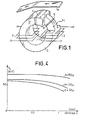
- FIG. 1 represents a recording-reading head with two air gaps according to the known art.
- the magnetic circuit 1 consists of a magnetic circuit 1 in the form of a torus and two recording 2 and reading 3 windings, crossed by the magnetic circuit.
- This is provided with two air gaps 4 and 5, respectively for recording and reading, both of which are filled with shims 6, 7 made of a non-magnetic material such as brass.
- the reading air gap 5 is transversely of width (L,) less than that (L z ) of the recording air gap 4, to obtain that, for the reasons explained above, during the successive passages of the magnetizable support 8 in front in the air gaps, the width of the track actually is less than the width of the recorded track.
- a magnetic head of this type has the disadvantage of not ensuring the separation of the functions of the air gaps, and it can be seen, at the respective stages of recording and reading, that the two air gaps record and read simultaneously, with creation of spurious offset signals. in time.
- FIG. 2 represents a record-read head with a single air gap according to the known art.
- the head is characterized by the fact that the respective transverse dimensions L 1 and L 2 of the two pole surfaces opposite the single air gap are different.
- the magnetic state of the magnetizable support is defined, as has also been explained above, by the field existing at the outlet edge 11 of the air gap, corresponding to the width L 2 which is the large transverse dimension of the air gap.
- the magnetic efficiency of the lateral parts of the outlet edge is obtained, for the most part, thanks to the leakage force lines such as 12 and 13, which close laterally in the air the force lines of the induction prevailing in the magnetic circuit.
- FIG. 3 represents a recording-reading head according to the invention, comprising a lateral air gap field distributor.
- the magnetic reluctance presented to the lines of leakage force 12, 13 in the air of the head of FIG. 2 is reduced, by arranging, on each side of the pole surface corresponding to the small transverse width L 1 , two plates 21 and 22 of magnetic material, constituting a lateral field distributor in the air gap, in one piece with the pole piece of width L 1 .
- This distributor further increases the useful induction which prevails in the entire magnetic circuit of the head, and its role thus extends until the improvement of the output level of the electrical signal collected at the terminals of the windings in reading.
- FIG. 4 represents a diagram, in rectangular axes, summarizing the experimental studies made by the Applicant, on the one hand on the thickness of the lateral plates, on the other hand on the sensitivity to transverse shifts due to the instability of scrolling.
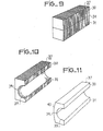
- Figures 5 to 13 show the different steps of a method of manufacturing a magnetic head according to the invention.
- FIG. 6 there are shown two ferrite plates 30, 31 perfectly rectified and polished, plates between which there is interposed a thin layer of non-magnetic ferrite 32 ( Figure 6a).
- a zinc ferrite paste 33 is deposited on the magnetic ferrite plate 31.
- the thickness of the ferrite film or of ferrite paste is between 10 and 100 microns and preferably 10 and 60 microns.
- This non-magnetic layer is then sintered under pressure to obtain a block shown in FIG. 7, having a homogeneous structure.
- the non-magnetic area represented by 34 is therefore located in the median plane of this homogeneous block.
- a cutting operation then allows (see Figure 8) the production of bars such as 35, 36, 37, ... 38.
- Each substantially parallelepipedal block such as 37 (shown in Figure 9 in close-up) is then subjected to a grooving operation of a semi-cylindrical groove 39 (see FIG. 10), said groove being substantially symmetrical with respect to the plane containing the non-magnetic ferrite film 34,
- the following operation consists in performing a cylindrical surfacing of the parallelepiped bar (FIG.
- the following operation consists in cutting the bar of FIG. 11 into individual heads of width L (see FIG. 12), plus removing material by any suitable means so as to leave only a narrower part on the magnetic head. for the reading part, this part of the head having a width 1.
- These shoulders 43 and 44 have a thickness d, while the thickness of the air gap 45 has a value e.
- the two shoulders 43 and 44 will have the same dimensions, which gives symmetry to the read head, a structure which is preferable in order to fully benefit from the advantages of the invention.
- FIG. 13 a read and / or write head is shown diagrammatically. according to the invention as carried out according to the method described above.
- the upper part of this head conforms to the part shown in FIG. 12, while a magnetic closing circuit 46 in the form of a U has been added, as well as writing and reading windings 47 and 48 respectively.
- FIG. 14 shows a very enlarged view of the magnetic strip and a projection of the head according to the invention.
- the recording is carried out over the entire width L of the magnetic strip while the reading is carried out over the width 1, less than L.
- the current circulating in the coil generates a magnetic field which is channeled up to 'to the magnetic strip by the writing frame 41.
- the lines of force penetrate into the magnetic layer of the strip and find on the other side of the gap a section large enough to close in the frame 42 to right of the air gap. This allows writing on the total width of the active face L.
- the magnetic strip which is the seat of an induction which therefore generates a field moves through the reading coil and gives rise to an electromotive force at the terminals thereof.
- the sudden change in section of the active face, which goes from L to 1 means that the magnetic reluctance of the circuit is large at the edges and relatively low at the center, i.e. in the axis of the reading frame. .
- the width actually read on the magnetic tape has a value slightly greater than 1 but much smaller than L. This therefore effectively makes it possible to overcome the different mechanical tolerances involved in the operation of the systems for reading media. coated with magnetic tracks such as for example credit cards.
Description
La présente invention se rapporte au domaine de l'enregistrement magnétique, et concerne les transducteurs électro-magnétiques habituellement désignés sous le nom de "têtes". De tels transducteurs coopèrent avec un support magnétisable mobile dont les variations locales de l'état magnétique représentent l'enrigistrement proprement dit, et ont pour fonction de convertir ces variations en un signal électrique exploitable disponible à leurs bornes. Symétriquement, l'application d'un signal électrique à leurs bornes détermine une magnétisation variable dans le support magnétisable mobile qu'on fait défiler devant ces transducteurs.The present invention relates to the field of magnetic recording, and relates to electromagnetic transducers usually referred to as "heads". Such transducers cooperate with a mobile magnetizable support whose local variations in the magnetic state represent the actual recording, and have the function of converting these variations into an exploitable electrical signal available at their terminals. Symmetrically, the application of an electrical signal to their terminals determines a variable magnetization in the mobile magnetizable support which is scrolled in front of these transducers.
Le transfert des variations de magnétisme réciproques entre une telle tête et un support s'effectue par défilement de celui-ci devant un entrefer ménagé dans un circuit magnétique en forme générale de tore, et les variations de flux magnétique dont le circuit magnétique est le siège, sont soit créées, dans le cas de l'enregistrement, soit transformées en signal électrique, dans le cas de la lecture, par des enroulements en forme de bobinages traversés par le circuit magnétique.The transfer of reciprocal magnetism variations between such a head and a support is effected by scrolling of the latter in front of an air gap formed in a magnetic circuit in the general shape of a torus, and the variations in magnetic flux of which the magnetic circuit is the seat. , are either created, in the case of recording, or transformed into an electrical signal, in the case of reading, by windings in the form of coils crossed by the magnetic circuit.
Dans les utilisations pratiques, on fait le plus souvent appel à des têtes différentes pour l'enregistrement et la lecture, la largeur de l'entrefer et la matériau dont est constitué le circuit magnétique n'étant pas les mêmes si l'on désire optimiser le résultat de chaque opération. C'est le cas par exemple dans le domaine de l'électroacoustique.In practical use, we usually use different heads for recording and reading, the width of the air gap and the material of which the magnetic circuit is made are not the same if we want to optimize the result of each operation. This is the case, for example, in the field of electroacoustics.
Cependant, dans d'autres domaines, tel que celui des cartes à données magnétiques, par exemple les cartes de crédit, l'encombrement présenté par des têtes séparées ne permettrait pas de satisfaire aux normes définies par les règlements internationaux, et il a été proposé de réunir les deux têtes d'enregistrement et de lecture et un boîtier unique, les deux entrefers faisant partie de deux circuits magnétiques soit juxtaposés, soit même imbriquées l'un dans l'autre, dispositions permettant d'obtenir des entrefers successifs très proches l'un de l'autre.However, in other fields, such as that of magnetic data cards, for example credit cards, the space presented by separate heads would not make it possible to meet the standards defined by international regulations, and it has been proposed to combine the two recording and playback heads and a single housing, the two air gaps forming part of two magnetic circuits either juxtaposed or even nested one inside the other, arrangements making it possible to obtain successive air gaps very close l of each other.
La mise en oeuvre de deux entrefers distincts est justifiée, d'autre part, par une particularité de l'enregistrement magnétique, lorsqu'il est mis en oeuvre dans le domaine des cartes à données. Celles-ci se prêtent mal, par leur forme, et à l'opposé du cas des bandes magnétiques, à l'obtention d'un défilement géométrique parfaitement défini. En pratique, cette particularité se traduit par des fluctuations dans la position géométrique transversale du support pendant son défilement, conduisant à des instabilités du signal lorsqu'on fait passer devant une tête de lecture une piste magnétisée par la même tête utilisée en fonction enregistrement.The use of two separate air gaps is justified, on the other hand, by a particular feature of magnetic recording, when it is used in the field of data cards. These lend themselves badly, by their shape, and in contrast to the case of magnetic tapes, to obtain a perfectly defined geometric scroll. In practice, this peculiarity results in fluctuations in the transverse geometrical position of the support during its scrolling, leading to instabilities of the signal when a track magnetized by the same head used in the recording function is passed.
Pour s'affranchir des problèmes de tolérances mécaniques des emplacements des pistes magnétiques, on a constaté qu'il était nécessaire d'enregistrer une piste pratiquement 3 fois plus large que la largeur de la piste de lecture, disposition permettant d'assurer un niveau de lecture constant, même si des fluctuations transversales interviennent au cours du défilement de la carte devant la tête.To overcome the problems of mechanical tolerances of the locations of the magnetic tracks, it was found that it was necessary to record a track practically 3 times wider than the width of the reading track, an arrangement which ensures a level of constant reading, even if transverse fluctuations occur during the scrolling of the map in front of the head.
La réalisation de cette disposition ne présente pas de difficultés particulières: l'entrefer d'enregistrement est simplement choisi pour avoir, transversalement, une longueur triple de la longueur de l'entrefer de lecture.The realization of this arrangement does not present any particular difficulties: the recording air gap is simply chosen to have, transversely, a length three times the length of the reading air gap.
Cependant, comme il sera expliqué plus loin en détail, on constate en pratique que la séparation des fonctions des deux entrefers n'est pas complètement obtenue dans ces têtes combinées, bien que les enroulements électriques d'enregistrement et de lecture soient distincts; en fait, les deux entrefers successifs enregistrent et lisent simultanément tous les deux, de façon néfaste, les données magnétiques, déterminant des risques d'erreur, en particulier sur signaux numériques de type binaire.However, as will be explained later in detail, it can be seen in practice that the separation of the functions of the two air gaps is not completely obtained in these combined heads, although the electrical recording and reading windings are distinct; in fact, the two successive air gaps both record and read simultaneously, in a harmful manner, the magnetic data, determining risks of error, in particular on digital signals of binary type.
On est donc souvent conduit, dans les applications, à renoncer aux têtes à deux entrefers, et à choisir la solution simple de la tête à entrefer unique, assumant alternativement les fonctions d'enregistrement et de lecture. Cette solution présente l'inconvénient, secondaire dans le cas des enregistrements de données numériques de faire renoncer à l'optimisation des performances procurée par les têtes à deux entrefers distincts; mais elle interdit la lecture sur une largeur plus étroite que celle de la piste enregistrée, inconvénient dont on a montré plus haut l'importance.We are therefore often led, in applications, to give up the heads with two air gaps, and to choose the simple solution of the head with a single air gap, assuming alternately the functions of recording and reading. This solution has the drawback, secondary in the case of digital data records, of renouncing the performance optimization provided by heads with two separate air gaps; but it prohibits reading over a narrower width than that of the recorded track, a drawback of which the importance was shown above.
Il est connu du brevet américain 3 060 279 d'utiliser des têtes magnétiques comportant un entrefer unique dont les pièces polaires sont d'inégales largeurs, la pièce polaire la plus large définissant la largeur de la piste en écriture, tandis que la largeur la plus faible définit la largeur de piste en lecture. De cette manière, on évite la possibilité de litre des signaux qui n'ont pas été complétement effacés au cour de l'enregistrement précédent. Toutefois, une telle réalisation implique une réluctance magnétique relativement importante aux lignes de force de fuite dans l'air présenté entre les deuxsurfaces polaires.It is known from American patent 3,060,279 to use magnetic heads comprising a single air gap whose pole pieces are of unequal widths, the widest pole piece defining the width of the track in writing, while the widest width low sets the track width for playback. In this way, the possibility of literal signals which have not been completely erased during the previous recording is avoided. However, such an embodiment implies a relatively large magnetic reluctance at the lines of force of leakage in the air presented between the two polar surfaces.
Pour éviter cet inconvénient, il est suggéré dans le brevet américain 3 353 168 ou dans le brevet japonnais JP=A-5 235 616, d'adjoindre latéralement à la pièce polaire la plus étroite, deux barrettes afin d'améliorer d'une part, l'enregistrement sur et d'autre part, la lecture. Toutefois, une telle réalisation présente un inconvénient important. Ces barrettes étant rapportées sur la pièce polaire la plus large d'une part, et latéralement sur la pièce polaire la moins large d'autre part, on créé ainsi une prolongation de l'entrefer principal, mais également deux entrefers supplémentaires situés entre chacune des barrettes et la pièce polaire de faible largeur. Cette dernière est donc isolée magnétiquement desdites barrettes. Ceci se traduit en fonction enregistrement par deux zones non enregistrées, de largeur légèrement supérieure à la valeur de ces entrefers latéraux. Si au cours de la lecture, la pièce polaire de faible largeur correspondant à la largeur lue par la tête magnétique ne se trouve pas exactement disposée comme au cours de l'enregistrement, une seule partie du signal enregistré sera lue par le tête magnétique, une partie de la piste magnétique étant dépourvue de signal enregistré.To avoid this drawback, it is suggested in American patent 3,353,168 or in Japanese patent JP = A-5,235,616, to add laterally to the narrowest pole piece, two bars in order to improve on the one hand , recording on and secondly, playback. However, such an embodiment has a significant drawback. These bars being attached to the widest pole piece on the one hand, and laterally to the thinnest pole piece on the other hand, this creates an extension of the main air gap, but also two additional air gaps located between each of the bars and the pole piece narrow. The latter is therefore magnetically isolated from said bars. This results in recording function by two unregistered zones, of width slightly greater than the value of these lateral air gaps. If during reading, the small pole piece corresponding to the width read by the magnetic head is not exactly arranged as during recording, only one part of the recorded signal will be read by the magnetic head, a part of the magnetic stripe having no recorded signal.
La tête d'enregistrement et de lecture selon l'invention permet d'éviter cet inconvénient. Cette tête d'enregistrement et de lecture de données magnétiques comporte un circuit magnétique (1) muni d'un entrefer (10) en matériau non magnétique d'épaisseur comprise entre 2 et 100 microns délimité par deux faces polaires rectangulaires disposées en vis-à-vis, la première étant de largeur L2 supérieure à la largeur L, de la seconde qui comporte deux plaquettes réalisant avec elle au contact de l'entrefer une largeur L2, ainsi que des moyens électriques (2) et (3) pour l'application et l'extraction respectives sur un support mobile de signaux d'enregistrement et de lecture en coopération avec l'entrefer 10. Elle est caractérisée en ce que les plaquettes sont des plaquettes latérales réalisées d'un seul tenant avec la seconde pièce polaire sur une épaisseur inférieure ou égalé à 500 microns et donnant avec elle un contour rectangulaire égal à celui de la première pièce polaire, de manière à permettre un enregistrement de largeur de l'ordre de L2 et une lecture de largeur de l'ordre de L, sur le support mobile.The recording and reading head according to the invention makes it possible to avoid this drawback. This magnetic data recording and reading head comprises a magnetic circuit (1) provided with an air gap (10) made of non-magnetic material with a thickness of between 2 and 100 microns delimited by two rectangular polar faces arranged facing each other. screw, the first being of width L 2 greater than the width L, of the second which comprises two plates carrying with it in contact with the air gap a width L 2 , as well as electrical means (2) and (3) for the respective application and extraction on a mobile medium of recording and reading signals in cooperation with the
On constate ainsi qu'une pièce polaire d'un seul tenant de largeur identique à la pièce polaire la plus large sur une faible épaisseur puis ensuite de largeur réduite permet de bénéficier des avantages des têtes magnétiques à pièces polaires de largeurs différentes tout en évitant les inconvénients cités plus haut. A l'étape d'enregistrement, quand le support magnétique défile devant l'entrefer, son état magnétique final dépend seulement, toutes choses égales par ailleurs, du champ qui règne au niveau du bord de sortie de l'entrefer, champ qui varie à la fréquence du signal à enregistrer et à celle du signal de polarisation haute fréquence caractéristique de l'enregistrement magnétique. En revanche, à l'étape de lecture, le signal électrique recueilli aux bornes des enroulements dépend de la largeur elle-même de l'entrefer, la fréquence maximale qu'il est possible de lire avant annulation du signal correspond au cas où l'entrefer de lecture a une largeur égale à la longueur d'onde correspondante enregistrée sur le support.It is thus found that a pole piece in one piece of width identical to the widest pole piece over a small thickness and then of reduced width allows to benefit from the advantages of magnetic heads with pole pieces of different widths while avoiding the disadvantages mentioned above. At the recording stage, when the magnetic medium passes in front of the air gap, its final magnetic state depends only, all other things being equal, on the field which prevails at the exit edge of the air gap, which field varies with the frequency of the signal to be recorded and that of the high frequency polarization signal characteristic of magnetic recording. On the other hand, at the reading stage, the electrical signal collected at the terminals of the windings depends on the width itself of the air gap, the maximum frequency which it is possible to read before cancellation of the signal corresponds to the case where the reading gap has a width equal to the corresponding wavelength recorded on the support.
La tête d'enregistrement et de lecture de l'invention exploite cette différence.The recording and reading head of the invention exploits this difference.
A la lecture, les lignes de force du champ magnétique créé par le défilement du support magnétique restent localisées dans la partie de l'entrefer correspondant à la pièce polaire de largeur L,.On reading, the lines of force of the magnetic field created by the movement of the magnetic support remain localized in the part of the air gap corresponding to the pole piece of width L ,.
En revanche, à l'enregistrement, seul le bord de sortie de l'entrefer a un rôle et c'est celcui qui correspond à la dimension transversale de largeur L2 de la surface polaire de sortie.On the other hand, at the recording, only the exit edge of the air gap has a role and it is this which corresponds to the transverse dimension of width L 2 of the exit polar surface.
Suivant que la tête magnétique de l'invention est utilisée en régime d'enregistrement ou de lecture, il y a ainsi sélection automatique de la largeur transversale de la piste enregistrée ou lue.Depending on whether the magnetic head of the invention is used in recording or playback mode, there is thus automatic selection of the transverse width of the track recorded or read.
L'invention sera mieux comprise à l'aide de la description ci-après, en s'appuyant sur les dessins annexés où:
- - la figure 1 représente une tête d'enregistrement-lecture à deux entrefers selon l'art connu;
- - la figure 2 représente une tête d'enregistrement-lecture à entrefer unique selon l'art connu;
- - la figure 3 représente un exemple de réalisation de la tête d'enregistrement-lecture selon l'invention;
- - la figure 4 représente des diagrammes en axes rectangulaires, illustrant les résultats obtenus avec une tête magnétique selon l'invention, en fonction des principaux paramètres dimensionnels;
- - les figures 5 à 13 représentent les différentes étapes d'un procédé de fabrication d'une tête magnétique selon l'invention;
- - la figure 14 représente un grossissement d'une bande magnétique comportant une représentation des lignes de force du champ magnétique existant entre la couche magnétique et la tête magnétique au cours des operations de lecture et/ou ecriture.
- - Figure 1 shows a recording-reading head with two air gaps according to the known art;
- - Figure 2 shows a record-read head with single air gap according to the known art;
- - Figure 3 shows an embodiment of the recording-reading head according to the invention;
- - Figure 4 shows diagrams in rectangular axes, illustrating the results obtained with a magnetic head according to the invention, according to the main dimensional parameters;
- - Figures 5 to 13 show the different steps of a method of manufacturing a magnetic head according to the invention;
- FIG. 14 represents a magnification of a magnetic strip comprising a representation of the lines of force of the magnetic field existing between the magnetic layer and the magnetic head during the read and / or write operations.
La figure 1 représente une tête d'enregistrement-lecture à deux entrefers selon l'art connu.FIG. 1 represents a recording-reading head with two air gaps according to the known art.
Elle se compose d'un circuit magnétique 1 en forme de tore et de deux enroulements d'enregistrement 2 et de lecture 3, traversés par le circuit magnétique. Celui-ci est muni de deux entrefers 4 et 5, respectivement d'enregistrement et de lecture, l'un et l'autre étant remplis de cales 6, 7 faites d'un matériau non magnétique tel que le laiton. L'entrefer de lecture 5 est transversalement de largeur (L,) inférieure à celle (Lz) de l'entrefer d'enregistrement 4, pour obtenir que, pour les raisons exposées plus haut, lors des passages successifs du support magnétisable 8 devant les entrefers, la largeur de la piste réellement lui soit inférieure à la largeur de la piste enregistrée. Une tête magnétique de ce type présente l'inconvénient de ne pas assurer la séparation des fonctions des entrefers, et on constate, aux stades respectifs d'enregistrement et de lecture, que les deux entrefers enregistrent et lisent simultanément, avec création de signaux parasites décalés dans le temps.It consists of a
La figure 2 représente une tête d'enregistrement-lecture à entrefer unique selon l'art connu.FIG. 2 represents a record-read head with a single air gap according to the known art.
Les mêmes moyens étant désignés par les mêmes nombresrepères, la tête se caractérise par le fait que les dimensions transversales respectives L1 et L2 des deux surfaces polaires en vis-à-vis de l'entrefer unique sont differentes.The same means being designated by the same numbers, the head is characterized by the fact that the respective transverse dimensions L 1 and L 2 of the two pole surfaces opposite the single air gap are different.
Le fonctionnement d'une telle tête est le suivant:
- A l'étape de lecture d'un support magnétique enregistre, la largeur de piste lue est égale à Ll, dimension- transversale réduite de l'entrefer effectif, défini pour les raisons exposées plus haut, par les surfaces communes en vis-à-vis, appartenant aux deux surfaces polaires.
- At the reading stage of a recorded magnetic medium, the track width read is equal to L l , reduced transverse dimension of the effective air gap, defined for the reasons explained above, by the common surfaces opposite. -screw, belonging to the two polar surfaces.
En revanche, à l'étape d'enregistrement, l'état magnétique du support magnétisable est défini, ainsi qu'il a également été explique plus haut, par le champ existant au niveau du bord de sortie 11 de l'entrefer, correspondant à la largeur L2 qui est la grande dimension transversale de l'entrefer. L'efficacité magnétique des parties latérales du bord de sortie est obtenue, pour sa plus grande part, grâce aux lignes de force de fuite telles que 12 et 13, qui referment latéralement dans l'air les lignes de force de l'induction régnant dans le circuit magnétique.On the other hand, at the recording stage, the magnetic state of the magnetizable support is defined, as has also been explained above, by the field existing at the
Ainsi, suivant que les enroulements 2 et 3 sont placés en régime d'enregistrement ou de lecture, il y a sélection automatique de la largeur transversale L2 ou L1 de l'entrefer effectif d'enregistrement ou de lecture de la tête.Thus, depending on whether the
La figure 3 représente une tête d'enregistrement-lecture selon l'invention, comportant un répartiteur latéral de champ d'entrefer.FIG. 3 represents a recording-reading head according to the invention, comprising a lateral air gap field distributor.
Suivant l'invention, on réduit la réluctance magnétique présentée aux lignes de force de fuite 12, 13 dans l'air de la tête de la figure 2, en disposant, de chaque côté de la surface polaire correspondant à la petite largeur transversale L1, deux plaquettes 21 et 22 en matériau magnétique, constituant un répartiteur latéral de champ dans l'entrefer, d'un seul tenant avec la piece polaire de largeur L1. Ce répartiteur augmente de plus l'induction utile qui règne dans l'ensemble du circuit magnétique de la tête, et son rôle s'étend ainsi jusqu'à l'amélioration du niveau de sortie du signal électrique recueilli aux bornes des enroulements en régime de lecture.According to the invention, the magnetic reluctance presented to the lines of
Le choix des dimensions optimales, en épaisseur d et largeur transversale D, du répartiteur de champ de la figure 3, sont du domaine des essais systématiques.The choice of the optimal dimensions, in thickness d and transverse width D, of the field distributor of FIG. 3, are of the domain of systematic tests.
La figure 4 représente un diagramme, en axes rectangulaires, résumant les études expérimentales faites par la Demanderesse, d'une part sur l'épaisseur des plaquettes latérales, d'autre part sur la sensibilité aux décalages transversaux dus aux instabilités de défilement.FIG. 4 represents a diagram, in rectangular axes, summarizing the experimental studies made by the Applicant, on the one hand on the thickness of the lateral plates, on the other hand on the sensitivity to transverse shifts due to the instability of scrolling.
Ces courbes montrent notamment que le niveau de sortie en régime de lecture Vs augmente lorsque l'épaisseur des plaquettes latérales, constituant le répartiteur, augmente au delà de valeurs proches de la largeur de l'entrefer, typiquement 50 micromètres pour un entrefer de 10 micromètres: elles montrent aussi que, dans ces conditions, pour une piste lue de largeur moitié de celle de la piste enregistrée de 6,5 mm, la stabilité du niveau de sortie V en fonction des fluctuations géométriques transversales de position est excellente, typiquement de ±3% pour des décalages transversaux 8 du support mobile de ±0,9 mm, décalages supérieurs à ceux que les dispositifs modernes de défilement pour cartes à données magnétiques sont capables d'assurer.These curves show in particular that the output level in reading mode V s increases when the thickness of the side plates, constituting the distributor, increases beyond values close to the width of the air gap, typically 50 micrometers for an air gap of 10 micrometers: they also show that, under these conditions, for a read track half the width of that of the recorded track of 6.5 mm, the stability of the output level V as a function of the transverse geometric fluctuations in position is excellent, typically of ± 3% for
On doit observer, en terminant, que les résultats fournis par la tête magnétique de l'invention, indiqués ci-dessus, l'ont été à titre d'ordre de grandeur, et que les avantages procurés par l'invention ont été notamment vérifiés dans le cas d'entrefers de largeurs comprises entre 2 et 100 microns, d'épaisseurs de plaquette comprises entre 0 et 500 microns, et pour des vitesses de supports magnétiques comprises entre 30 mm et 1500 mm par seconde.It should be observed, in conclusion, that the results provided by the magnetic head of the invention, indicated above, were given by way of magnitude, and that the advantages obtained by the invention have been verified in particular in the case of air gaps of widths between 2 and 100 microns, of plate thicknesses between 0 and 500 microns, and for magnetic media speeds between 30 mm and 1500 mm per second.
Les figures 5 à 13 représentent les différentes étapes d'un procédé de fabrication d'une tête magnétique selon l'invention.Figures 5 to 13 show the different steps of a method of manufacturing a magnetic head according to the invention.
Sur la figure 5, on a représenté deux plaques de ferrite 30, 31 parfaitement rectifiées et polies, plaques entre lesquelles on interpose une fine couche de ferrite non magnétique 32 (figure 6a). Selon une autre variante de réalisation (figure 6b), on dépose une pâte de ferrite de zinc 33 sur la plaque de ferrite magnétique 31. Généralement, l'épaisseur du film de ferrite ou de pâte de ferrite est comprise entre 10 et 100 microns et de préférence de 10 et 60 microns.In Figure 5, there are shown two
On effectue ensuite le frittage de cette couche non magnétique sous pression pour obtenir un bloc représenté sur la figure 7, ayant une structure homogène. La zone non magnétique représentée par 34 est donc située dans le plan médian de ce bloc homogène. Une opération de tronçonnage permet ensuite (voir figure 8) la réalisation de barrettes telles que 35, 36, 37, ... 38. Chaque bloc sensiblement parallélépipédique tel que 37 (représenté sur la figure 9 en gros plan) est ensuite soumis à une opération de rainurage d'une gorge semi- cylindrique 39 (voir figure 10), ladite rainure étant sensiblement symétrique par rapport au plan contenant le film de ferrite non magnétique 34, L'opération suivante consiste à réaliser un surfaçage cylindrique du barreau parallélépipédique (figure 11) pour obtenir la face du travail 40 de la tête magnétique. L'opération suivant consiste à découperle barreau de la figure 11 en têtes individuelles de largeur L (voir figure 12) plus à réaliser un enlèvement de matière par tout moyen adapté de manière à ne laisser subsister sur la tête magnétique qu'une partie plus étroite pour la partie lecture, cette partie de la tête ayant une largeur 1. On obtient ainsi une tête telle que représentée sur la figure 12 possédant à droite sur cette figure une partie correspondant à la partie lecture de la tête ayant une largeur 1 inférieure à L, partie représentée par le chiffre 42, prolongée latéralement par deux épaulements 43 et 44 d'un seul tenant avec ladite partie 42. Ces épaulements 43 et 44 ont une épaisseur d, tandis que l'épaisseur de l'entrefer 45 a une valeur e. Il est à remarquer, bien entendu, que de préférence, les deux épaulements 43 et 44 auront les mêmes dimensions, ce qui donne une symétrie à la tête de lecture, structure préférable pour bénéficier pleinement des avantages de l'invention.This non-magnetic layer is then sintered under pressure to obtain a block shown in FIG. 7, having a homogeneous structure. The non-magnetic area represented by 34 is therefore located in the median plane of this homogeneous block. A cutting operation then allows (see Figure 8) the production of bars such as 35, 36, 37, ... 38. Each substantially parallelepipedal block such as 37 (shown in Figure 9 in close-up) is then subjected to a grooving operation of a semi-cylindrical groove 39 (see FIG. 10), said groove being substantially symmetrical with respect to the plane containing the
Sur la figure 13, on a représenté schématiquement une tête de lecture et/ou d'écriture. conforme à l'invention telle que réalisée selon le procédé décrit ci-dessus. La partie supérieure de cette tête est conforme à la partie représentée sur la figure 12 tandis que l'on a rejouté un circuit magnétique de fermeture 46 en forme de U, ainsi que des bobinages respectivement d'écriture et de lecture 47 et 48.In FIG. 13, a read and / or write head is shown diagrammatically. according to the invention as carried out according to the method described above. The upper part of this head conforms to the part shown in FIG. 12, while a
Sur la figure 14, on a représenté une vue très grossie de la bande magnétique et une projection de la tête selon l'invention. L'enregistrement s'effectue sur toute la largeur L de la bande magnétique tandis que la lecture s'effectue sur la largeur 1, inférieure à L. Dans la phase écriture, le courant circulant dans la bobine engendre un champ magnétique qui est canalisé jusqu'à la bande magnétique par l'armature d'écriture 41. Les lignes de force pénètrent dans la couche magnétique de la bande et retrouvent de l'autre côté de l'entrefer une section suffisamment importante pour se refermer dans l'armature 42 à droite de l'entrefer. Ceci permet une écriture sur la largeur totale de la face active L.FIG. 14 shows a very enlarged view of the magnetic strip and a projection of the head according to the invention. The recording is carried out over the entire width L of the magnetic strip while the reading is carried out over the
En fonction lecture, la bande magnétique qui est le siège d'une induction qui engendre donc un champ se déplace au travers de la bobine de lecture et donne naissance à une force électromotrice aux bornes de celle-ci. Le changement brutal de section de la face active qui passe de L à 1, fait que la réluctance magnétique du circuit est grande sur les bords et relativement faible au centre c'est-à-dire dans l'axe de l'armature de lecture. Dans ces conditions, la largeur effectivement lue sur la bande magnétique a une valeur légèrement plus grande que 1 mais beaucoup plus faible que L. Ceci permet donc effectivement de pallier aux différentes tolérances mécaniques mises en jeu dans l'exploitation des systèmes de lecture de supports revêtus de pistes magnétiques tels que par exemple les cartes de crédit.In reading function, the magnetic strip which is the seat of an induction which therefore generates a field moves through the reading coil and gives rise to an electromotive force at the terminals thereof. The sudden change in section of the active face, which goes from L to 1, means that the magnetic reluctance of the circuit is large at the edges and relatively low at the center, i.e. in the axis of the reading frame. . Under these conditions, the width actually read on the magnetic tape has a value slightly greater than 1 but much smaller than L. This therefore effectively makes it possible to overcome the different mechanical tolerances involved in the operation of the systems for reading media. coated with magnetic tracks such as for example credit cards.
On doit noter aussi que, bien que la description ait été faite dans le cas d'une tête à enroulements, le cas d'une tête de lecture à effet Hall doit être compris dans le domaine de l'invention.It should also be noted that, although the description has been made in the case of a winding head, the case of a Hall effect reading head must be included in the field of the invention.
On doit enfin remarquer que, bien que la description ait été particulièrement centrée sur le cas des cartes à données magnétiques, le domaine de l'invention s'étend à toute autre forme de support, telle que celle d'un disque magnétique souple ou rigide.Finally, it should be noted that, although the description has been particularly centered on the case of magnetic data cards, the field of the invention extends to any other form of support, such as that of a flexible or rigid magnetic disc. .
Claims (4)
Applications Claiming Priority (2)
| Application Number | Priority Date | Filing Date | Title |
|---|---|---|---|
| FR8005418 | 1980-03-11 | ||
| FR8005418A FR2478357A1 (en) | 1980-03-11 | 1980-03-11 | MAGNETIC HEAD FOR RECORDING AND READING MAGNETIC DATA WITH VARIABLE TRACK WIDTH |
Publications (2)
| Publication Number | Publication Date |
|---|---|
| EP0035943A1 EP0035943A1 (en) | 1981-09-16 |
| EP0035943B1 true EP0035943B1 (en) | 1984-07-11 |
Family
ID=9239539
Family Applications (1)
| Application Number | Title | Priority Date | Filing Date |
|---|---|---|---|
| EP81400351A Expired EP0035943B1 (en) | 1980-03-11 | 1981-03-06 | Magnetic head with variable track-width for writing or reading magnetic data |
Country Status (6)
| Country | Link |
|---|---|
| US (1) | US4405959A (en) |
| EP (1) | EP0035943B1 (en) |
| JP (1) | JPS56134310A (en) |
| DE (1) | DE3164649D1 (en) |
| ES (2) | ES500235A0 (en) |
| FR (1) | FR2478357A1 (en) |
Families Citing this family (15)
| Publication number | Priority date | Publication date | Assignee | Title |
|---|---|---|---|---|
| JPS57189325A (en) * | 1981-05-18 | 1982-11-20 | Toshiba Corp | Composite magnetic head |
| DE3376903D1 (en) * | 1982-10-01 | 1988-07-07 | Mitsubishi Electric Corp | Disc drive for flexible discs with different track widths |
| NL8302093A (en) * | 1983-06-13 | 1985-01-02 | Philips Nv | MAGNETIC TRANSFER HEAD FOR WRITING INFORMATION ON HIGH-COERCITIVE REGISTRATION MEDIA. |
| US4819107A (en) * | 1984-08-29 | 1989-04-04 | Irwin Magnetic Systems, Inc. | Magnetic transducer head structure |
| KR860002082A (en) * | 1984-08-29 | 1986-03-26 | 프랑시스 글로리 | Magnetic transducer head structure |
| JPH0831204B2 (en) * | 1985-10-18 | 1996-03-27 | 富士通株式会社 | Thin film magnetic head |
| US4821126A (en) * | 1985-10-22 | 1989-04-11 | Fuji Photo Film Co., Ltd. | Magnetic recording method involving core pieces of different thickness |
| US4849841A (en) * | 1987-04-10 | 1989-07-18 | Irwin Magnetic Systems, Inc. | Transducer head core structure with recessed magnetic closures |
| US4883950A (en) * | 1987-05-23 | 1989-11-28 | The Furukawa Electric Co., Ltd. | Composite magnetic and optical head |
| US5007158A (en) * | 1988-02-09 | 1991-04-16 | Sanyo Electric Co., Ltd. | Method of manufacturing magnetic heads |
| JP2600841B2 (en) * | 1988-09-02 | 1997-04-16 | 三菱電機株式会社 | Magnetic head |
| US5706145A (en) * | 1994-08-25 | 1998-01-06 | Hindman; Carl L. | Apparatus and methods for audio tape indexing with data signals recorded in the guard band |
| US5734533A (en) * | 1996-05-15 | 1998-03-31 | Read-Rite Corporation | Dual gap magnetic head and method of making the same |
| JPH10247305A (en) * | 1997-03-03 | 1998-09-14 | Sanyo Electric Co Ltd | Production of composite type thin-film magnetic head |
| GB0420443D0 (en) * | 2004-09-14 | 2004-10-20 | Ncr Int Inc | A card reader |
Family Cites Families (14)
| Publication number | Priority date | Publication date | Assignee | Title |
|---|---|---|---|---|
| US2947592A (en) * | 1955-08-25 | 1960-08-02 | Sperry Rand Corp | High frequency magnetic transducers |
| GB831492A (en) * | 1955-09-06 | 1960-03-30 | Ibm | Improvements in magnetic transducers |
| GB900652A (en) * | 1957-11-06 | 1962-07-11 | Emi Ltd | Improvements in or relating to magnetic transducing heads |
| US3209078A (en) * | 1960-12-20 | 1965-09-28 | Siemens Ag | Magnetic head equipped with a hall generator |
| DE1167053B (en) * | 1961-10-17 | 1964-04-02 | Telefunken Patent | Erase head for deleting two audio tracks separately in two-track operation and for erasing full-track recordings |
| US3353168A (en) * | 1964-04-09 | 1967-11-14 | Potter Instrument Co Inc | Wide-record narrow-read magnetic head |
| NL7210322A (en) * | 1972-07-26 | 1974-01-29 | ||
| JPS5838843B2 (en) * | 1973-11-20 | 1983-08-25 | ティーディーケイ株式会社 | Magnetic recording and reproducing method |
| US4085430A (en) * | 1974-01-24 | 1978-04-18 | U.S. Philips Corporation | Thin film magnetic head with a gap formed between a loop shaped core part and a bridging core part |
| JPS51147312A (en) * | 1975-06-13 | 1976-12-17 | Canon Inc | Magnetic head |
| JPS5235616A (en) * | 1975-09-16 | 1977-03-18 | Alps Nootoronikusu Kk | Magnetic head |
| GB1500593A (en) * | 1976-10-19 | 1978-02-08 | Data Recording Instr Co | Magnetic transducing heads |
| JPS545417A (en) * | 1977-06-14 | 1979-01-16 | Tdk Corp | Magnetic head |
| JPS5842579A (en) * | 1981-09-09 | 1983-03-12 | 株式会社日立製作所 | Speed feedback type hydraulic elevator device |
-
1980
- 1980-03-11 FR FR8005418A patent/FR2478357A1/en active Granted
-
1981
- 1981-03-06 DE DE8181400351T patent/DE3164649D1/en not_active Expired
- 1981-03-06 EP EP81400351A patent/EP0035943B1/en not_active Expired
- 1981-03-09 US US06/242,157 patent/US4405959A/en not_active Expired - Lifetime
- 1981-03-10 ES ES500235A patent/ES500235A0/en active Granted
- 1981-03-11 JP JP3513381A patent/JPS56134310A/en active Pending
- 1981-05-19 ES ES502314A patent/ES8206074A1/en not_active Expired
Also Published As
| Publication number | Publication date |
|---|---|
| US4405959A (en) | 1983-09-20 |
| DE3164649D1 (en) | 1984-08-16 |
| EP0035943A1 (en) | 1981-09-16 |
| FR2478357B1 (en) | 1984-04-06 |
| ES8202446A1 (en) | 1982-01-16 |
| ES500235A0 (en) | 1982-01-16 |
| ES502314A0 (en) | 1982-07-16 |
| FR2478357A1 (en) | 1981-09-18 |
| JPS56134310A (en) | 1981-10-21 |
| ES8206074A1 (en) | 1982-07-16 |
Similar Documents
| Publication | Publication Date | Title |
|---|---|---|
| EP0035943B1 (en) | Magnetic head with variable track-width for writing or reading magnetic data | |
| FR2559293A1 (en) | NOVEL MAGNETIC WRITE AND READ HEAD FOR MAGNETIC RECORDING AND METHOD FOR MANUFACTURING THE SAME | |
| EP0188944A1 (en) | System for perpendicular recording and method for fabricating a magnetic head | |
| FR2612676A1 (en) | MAGNETIC READING HEAD FOR VERY LOW WIDTH TRACK AND METHOD FOR MANUFACTURING THE SAME | |
| EP0677838A2 (en) | Magnetic head matrix device, especially made of thin layers | |
| EP0046697B1 (en) | Integrated magnetic transducer | |
| EP0452193B1 (en) | Fabrication processes of a magnetic recording/reproducing head | |
| EP0040994B1 (en) | Magnetic transducer having a variable largest dimension gap for playing back or recording information on a magnetic carrier | |
| EP0041409A1 (en) | Magnetic transducer for the playback or recording of information of a magnetic carrier | |
| EP1810283A2 (en) | Recording and/or playback device comprising multiple magnetic heads with azimuth gaps | |
| EP0188943B1 (en) | Magnetic write transducer for transverse recording | |
| FR2518792A1 (en) | MAGNETIC HEAD WITH HALL EFFECT | |
| EP0028177B1 (en) | Integrated magnetic transducer | |
| EP0132186B1 (en) | Highly integrated magnetic transducer for writing information on a magnetic carrier | |
| EP0314557A2 (en) | Recording/reproducing magnetic head including a superconductor material | |
| EP0800160A1 (en) | Method for manufacturing a double magnetic head with opposite gap-azimuth | |
| EP0409673B1 (en) | Integrated magnetic recording head | |
| EP1810284A1 (en) | Recording and/or playback device comprising multiple azimuth magnetic heads | |
| FR2802011A1 (en) | PLANAR READING HEAD WITH MAGNETO-RESISTIVE ELEMENT | |
| EP0550322A1 (en) | Method of fabrication of a magnetic head for layers with high coercitive fields | |
| JP3171183B2 (en) | Recording / playback separation combined magnetic head | |
| EP0406229A1 (en) | Magnetic head for magnetic tracks with high coercive field and fabrication method | |
| FR2633427A1 (en) | Magnetic recording/reading head using a superconducting material | |
| WO2001052245A1 (en) | High density multi-track magnetic write head |
Legal Events
| Date | Code | Title | Description |
|---|---|---|---|
| PUAI | Public reference made under article 153(3) epc to a published international application that has entered the european phase |
Free format text: ORIGINAL CODE: 0009012 |
|
| AK | Designated contracting states |
Designated state(s): DE FR GB IT SE |
|
| 17P | Request for examination filed |
Effective date: 19811019 |
|
| RAP1 | Party data changed (applicant data changed or rights of an application transferred) |
Owner name: L.C.C.-C.I.C.E. - COMPAGNIE EUROPEENNE DE COMPOSAN |
|
| ITF | It: translation for a ep patent filed |
Owner name: JACOBACCI & PERANI S.P.A. |
|
| GRAA | (expected) grant |
Free format text: ORIGINAL CODE: 0009210 |
|
| AK | Designated contracting states |
Designated state(s): DE FR GB IT SE |
|
| REF | Corresponds to: |
Ref document number: 3164649 Country of ref document: DE Date of ref document: 19840816 |
|
| RAP2 | Party data changed (patent owner data changed or rights of a patent transferred) |
Owner name: L.C.C.-C.I.C.E. - COMPAGNIE EUROPEENNE DE COMPOSAN |
|
| PLBE | No opposition filed within time limit |
Free format text: ORIGINAL CODE: 0009261 |
|
| STAA | Information on the status of an ep patent application or granted ep patent |
Free format text: STATUS: NO OPPOSITION FILED WITHIN TIME LIMIT |
|
| 26N | No opposition filed | ||
| ITTA | It: last paid annual fee | ||
| EAL | Se: european patent in force in sweden |
Ref document number: 81400351.3 |
|
| PGFP | Annual fee paid to national office [announced via postgrant information from national office to epo] |
Ref country code: SE Payment date: 19950217 Year of fee payment: 15 |
|
| PGFP | Annual fee paid to national office [announced via postgrant information from national office to epo] |
Ref country code: GB Payment date: 19950220 Year of fee payment: 15 Ref country code: DE Payment date: 19950220 Year of fee payment: 15 |
|
| PGFP | Annual fee paid to national office [announced via postgrant information from national office to epo] |
Ref country code: FR Payment date: 19950324 Year of fee payment: 15 |
|
| PG25 | Lapsed in a contracting state [announced via postgrant information from national office to epo] |
Ref country code: GB Effective date: 19960306 |
|
| PG25 | Lapsed in a contracting state [announced via postgrant information from national office to epo] |
Ref country code: SE Effective date: 19960307 |
|
| GBPC | Gb: european patent ceased through non-payment of renewal fee |
Effective date: 19960306 |
|
| PG25 | Lapsed in a contracting state [announced via postgrant information from national office to epo] |
Ref country code: FR Effective date: 19961129 |
|
| EUG | Se: european patent has lapsed |
Ref document number: 81400351.3 |
|
| PG25 | Lapsed in a contracting state [announced via postgrant information from national office to epo] |
Ref country code: DE Effective date: 19970101 |
|
| REG | Reference to a national code |
Ref country code: FR Ref legal event code: ST |