EP0314557A2 - Recording/reproducing magnetic head including a superconductor material - Google Patents
Recording/reproducing magnetic head including a superconductor material Download PDFInfo
- Publication number
- EP0314557A2 EP0314557A2 EP88402673A EP88402673A EP0314557A2 EP 0314557 A2 EP0314557 A2 EP 0314557A2 EP 88402673 A EP88402673 A EP 88402673A EP 88402673 A EP88402673 A EP 88402673A EP 0314557 A2 EP0314557 A2 EP 0314557A2
- Authority
- EP
- European Patent Office
- Prior art keywords
- magnetic
- layer
- recording
- air gap
- superconductive material
- Prior art date
- Legal status (The legal status is an assumption and is not a legal conclusion. Google has not performed a legal analysis and makes no representation as to the accuracy of the status listed.)
- Withdrawn
Links
Images


Classifications
-
- G—PHYSICS
- G11—INFORMATION STORAGE
- G11B—INFORMATION STORAGE BASED ON RELATIVE MOVEMENT BETWEEN RECORD CARRIER AND TRANSDUCER
- G11B5/00—Recording by magnetisation or demagnetisation of a record carrier; Reproducing by magnetic means; Record carriers therefor
- G11B5/127—Structure or manufacture of heads, e.g. inductive
- G11B5/1278—Structure or manufacture of heads, e.g. inductive specially adapted for magnetisations perpendicular to the surface of the record carrier
-
- G—PHYSICS
- G11—INFORMATION STORAGE
- G11B—INFORMATION STORAGE BASED ON RELATIVE MOVEMENT BETWEEN RECORD CARRIER AND TRANSDUCER
- G11B5/00—Recording by magnetisation or demagnetisation of a record carrier; Reproducing by magnetic means; Record carriers therefor
- G11B5/127—Structure or manufacture of heads, e.g. inductive
- G11B5/17—Construction or disposition of windings
-
- G—PHYSICS
- G11—INFORMATION STORAGE
- G11B—INFORMATION STORAGE BASED ON RELATIVE MOVEMENT BETWEEN RECORD CARRIER AND TRANSDUCER
- G11B5/00—Recording by magnetisation or demagnetisation of a record carrier; Reproducing by magnetic means; Record carriers therefor
- G11B5/127—Structure or manufacture of heads, e.g. inductive
- G11B5/187—Structure or manufacture of the surface of the head in physical contact with, or immediately adjacent to the recording medium; Pole pieces; Gap features
- G11B5/23—Gap features
- G11B5/235—Selection of material for gap filler
-
- G—PHYSICS
- G11—INFORMATION STORAGE
- G11B—INFORMATION STORAGE BASED ON RELATIVE MOVEMENT BETWEEN RECORD CARRIER AND TRANSDUCER
- G11B5/00—Recording by magnetisation or demagnetisation of a record carrier; Reproducing by magnetic means; Record carriers therefor
- G11B5/127—Structure or manufacture of heads, e.g. inductive
- G11B5/31—Structure or manufacture of heads, e.g. inductive using thin films
- G11B5/3109—Details
- G11B5/312—Details for reducing flux leakage between the electrical coil layers and the magnetic cores or poles or between the magnetic cores or poles
- G11B5/3123—Details for reducing flux leakage between the electrical coil layers and the magnetic cores or poles or between the magnetic cores or poles by using special coil configurations or conductors
- G11B5/3126—Details for reducing flux leakage between the electrical coil layers and the magnetic cores or poles or between the magnetic cores or poles by using special coil configurations or conductors using superconductors
-
- G—PHYSICS
- G11—INFORMATION STORAGE
- G11B—INFORMATION STORAGE BASED ON RELATIVE MOVEMENT BETWEEN RECORD CARRIER AND TRANSDUCER
- G11B5/00—Recording by magnetisation or demagnetisation of a record carrier; Reproducing by magnetic means; Record carriers therefor
- G11B5/127—Structure or manufacture of heads, e.g. inductive
- G11B5/31—Structure or manufacture of heads, e.g. inductive using thin films
- G11B5/3109—Details
- G11B5/313—Disposition of layers
- G11B5/3143—Disposition of layers including additional layers for improving the electromagnetic transducing properties of the basic structure, e.g. for flux coupling, guiding or shielding
- G11B5/3159—Disposition of layers including additional layers for improving the electromagnetic transducing properties of the basic structure, e.g. for flux coupling, guiding or shielding superconductive layers
-
- G—PHYSICS
- G11—INFORMATION STORAGE
- G11B—INFORMATION STORAGE BASED ON RELATIVE MOVEMENT BETWEEN RECORD CARRIER AND TRANSDUCER
- G11B5/00—Recording by magnetisation or demagnetisation of a record carrier; Reproducing by magnetic means; Record carriers therefor
- G11B5/10—Structure or manufacture of housings or shields for heads
- G11B5/11—Shielding of head against electric or magnetic fields
Definitions
- the present invention relates to a magnetic recording / reading head comprising a superconductive material and in particular a magnetic head in which a superconductive material is used to channel the magnetic flux emitted by the head towards the magnetic recording medium.
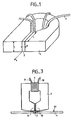
- a massive magnetic head known in the art as shown in FIG. 1, has good writing efficiency because the section of the magnetic circuit can be easily reduced at the air gap so as to concentrate the flux. On the other hand, they present a reading signal / noise ratio which is not optimized for the following reason:
- the planar coil 3 made of superconductive material and isolated from the preceding layers by an insulating material 8.
- the insulation of this coil is completed, above, by an insulating material 8 ⁇ .
- heads more specifically adapted to perpendicular recording that is to say heads in which the component of the magnetic field perpendicular to the surface of the recording medium is preponderant with respect to the longitudinal component.
- the basic principle used for this purpose is to keep only one pole of the magnetic circuit 1 in the active area of the head, the rest of the circuit can be closed on the recording medium by a so-called auxiliary pole or can be considered to be closed at infinity.
- Such a single pole recording head is shown in FIG. 7.
Abstract
Description
La présente invention concerne une tête magnétique d'enregistrement/lecture comportant un matériau supraconducteur et notamment une tête magnétique dans laquelle un matériau supraconducteurest utilisé pour canaliser le flux magnétique émis par la tête vers le support d'enregistrement magnétique.The present invention relates to a magnetic recording / reading head comprising a superconductive material and in particular a magnetic head in which a superconductive material is used to channel the magnetic flux emitted by the head towards the magnetic recording medium.
Pour mettre en évidence l'intérêt de l'invention on va tout d'abord décrire de manière générale les têtes magnétiques d'enregistrement/lecture existantes.To demonstrate the advantage of the invention, we will first of all describe in general the existing recording / reading magnetic heads.
Les têtes magnétiques d'enregistrement/lecture sont constituées d'un circuit magnétique 1 à perméabilité élevée comportant un entrefer non magnétique 2 d'épaisseur e et d'un circuit électrique 3 qui entoure le circuit magnétique 1 (figure 1).The magnetic recording / reading heads consist of a magnetic circuit 1 with high permeability comprising a
Lorsque le circuit 3 est parcouru par un courant, il émet un champ magnétique H qui est capté par le circuit 1 et concentré au niveau de l'entrefer 2 . Réciproquement, une variation locale de flux au niveau de l'entrefer 2 induit une tension V aux bornes du circuit 3.When the
Les têtes actuelles peuvent être divisées en deux familles :
- les têtes massives réalisées par usinage et assemblage de demi-têtes en matériau magnétique (exemples : têtes audio en ferrite ou en métal magnétique, têtes vidéo familiales (VHS) en monocristal de ferrite). Le circuit 3 est bobiné après assemblage
- les têtes couches minces, telles que représentées en figure 2, réalisées par dépôts successifs de couches minces de matériaux magnétiques de diélectriques, et de pistes conductrices gravées de manière à réaliser les éléments 1, 2 et 3.Current heads can be divided into two families:
- massive heads produced by machining and assembling half-heads made of magnetic material (examples: audio heads made of ferrite or magnetic metal, family video heads (VHS) made of ferrite single crystal).
- the thin film heads, as shown in FIG. 2, produced by successive depositions of thin layers of magnetic dielectric materials, and of tracks conductive engraved so as to produce
Chacune de ces familles peut être utilisée :
- soit pour l'enregistrement longitudinal, c'est à dire avec un milieu d'enregistrement dans lequel l'aimantation est parallèle au support et au défilement de la bande
- soit pour l'enregistrement perpendiculaire ou vertical, c'est à dire avec un milieu d'enregistrement dans lequel l'aimantation est perpendiculaire au support et au défilement de la bande.Each of these families can be used:
- or for longitudinal recording, that is to say with a recording medium in which the magnetization is parallel to the support and to the running of the tape
- Either for perpendicular or vertical recording, ie with a recording medium in which the magnetization is perpendicular to the support and to the running of the tape.
Pour ce deuxième type d'enregistrement, il peut être préférable d'utiliser des têtes dans lesquelles le circuit magnétique 1 n'est pas refermé au niveau de l'entrefer 2 par deux pôles symétriques, l'un des pôles seulement jouant un rôle actif dans l'enregistrement. Il s'agit alors de tête à pôle principal ou à pôle unique (single pole).For this second type of recording, it may be preferable to use heads in which the magnetic circuit 1 is not closed at the
Le critère principal pour caractériser une tête est le rapport signal/bruit qui doit être le plus grand possible.
- ηla valeur du signal est déterminée par l'efficacité (en écriture et par réciprocité en lecture)
η = H(x) /Ho
avec H(x) = champ magnétique à l'écriture à une distance x de l'entrefer.
Ho = champ maximal théorique à l'écriture
= ni/e
i= courant dans le circuit 3
n= nombre de tours du circuit 3
e= épaisseur de l'entrefer.
- le bruit intrinsèque de la tête (bruit thermique) est proportionnel à la partie réelle de l'impédance
R= RB + RL
avec RB = résistance du bobinage
=ρl/s

l = longueur du fil proportionnelle au nombre de tours du circuit 3
s = section du fil
L = inductance de la tête proportionnelle à n2
µ˝e = partie imaginaire de la perméabilité efficace du circuit magnétique
µ′e = partie réelle de la perméabilité efficace du circuit magnétique.The main criterion for characterizing a head is the signal / noise ratio which must be as large as possible.
- ηthe signal value is determined by the efficiency (in writing and in reciprocity in reading)
η = H (x) / Ho
with H (x) = magnetic field when writing at a distance x from the air gap.
Ho = maximum theoretical field at writing
= ni / e
i = current in
n = number of laps of
e = thickness of the air gap.
- the intrinsic noise of the head (thermal noise) is proportional to the real part of the impedance
R = R B + R L
with R B = winding resistance
= ρl / s
l = length of the wire proportional to the number of turns of
s = wire section
L = head inductance proportional to n2
µ˝e = imaginary part of the effective permeability of the magnetic circuit
µ ′ e = real part of the effective permeability of the magnetic circuit.
L'objet de l'invention est donc de fournir des moyens permettant d'augmenter le rapport signal/bruit d'une tête magnétique.The object of the invention is therefore to provide means making it possible to increase the signal / noise ratio of a magnetic head.
L'invention est applicable aux différents types de têtes et elle concerne particulièrement :
- les têtes massives pour enregistrement longitudinal ou éventuellement perpendiculaire.
- les têtes couches minces pour enregistrement longitudinal ou éventuellement perpendiculaire.
- les têtes à pôle principal ou unique pour enregistrement perpendiculaire.The invention is applicable to different types of heads and it particularly relates to:
- solid heads for longitudinal or possibly perpendicular recording.
- thin film heads for longitudinal or possibly perpendicular recording.
- main or single pole heads for perpendicular recording.
L'invention concerne donc une tête magnétique d'enregistrement/lecture comportant un circuit magnétique terminé par deux pôles magnétiques séparés par un entrefer l'ensemble des pôles magnétiques et de l'entrefer étant disposé à proximité d'une surface d'enregistrement d'un support d'enregistrement magnétique caractérisé en ce que l'entrefer comporte au moins une couche d'un matériau supraconducteur disposée sensiblement perpendiculairement à la surface d'enregistrement du support d'enregistrement .The invention therefore relates to a magnetic recording / reading head comprising a magnetic circuit terminated by two magnetic poles separated by an air gap all of the magnetic poles and of the air gap being disposed near a recording surface of a magnetic recording medium characterized in that the air gap comprises at least one layer of a superconductive material disposed substantially perpendicular to the recording surface of the recording medium.
L'invention concerne également une tête magnétique d'enregistrement/lecture en couches minces caractérisé en ce qu'il comprend un circuit inducteur (3) de champ magnétique réalisé en couche mince à l'aide d'un matériau supraconducteur.The invention also relates to a magnetic recording / reading head in thin layers, characterized in that it comprises a magnetic field inductor circuit (3) produced in a thin layer using a superconductive material.
L'invention concerne également une tête magnétique d'enregistrement/lecture à pôle unique comprenant un pôle unique muni d'un enroulement d'induction de champ magnétique et possédant une extrémité d'émission de champ magnétique comportant une face d'émission disposée à proximité d'une surface d'enregistrement d'un support d'enregistrement magnétique de façon à émettre un champ magnétique perpendiculairement à la surface d'enregistrement caractérisé en ce qu'elle comporte au moins une gaine en matériau supraconducteur englobant l'extrémité d'émission excepté la face d'émission.The invention also relates to a magnetic recording / reading head with a single pole comprising a single pole provided with a magnetic field induction winding and having a magnetic field emission end comprising a transmitting face disposed nearby. of a recording surface of a magnetic recording medium so as to emit a magnetic field perpendicular to the recording surface characterized in that it comprises at least one sheath of superconductive material encompassing the emission end except the emission face.
Enfin l'invention concerne un procédé de réalisation d'une tête d'enregistrement/lecture, caractérisé en ce qu'il comporte les étapes suivantes :
- - a) réalisation sur une partie de la couche, d'une couche en matériau magnétique ;
- - b) réalisation sur la partie restante de la couche, d'une couche d'isolant ;
- - c) réalisation sur le matériau magnétique et l'isolant d'une couche d'isolant présentant en son centre une partie ne comportant pas d'isolant et laissant libre le matériau magnétique ;
- - d) réalisation sur la couche d'isolant d'un bobinage en matériau supraconducteur et sur le matériau magnétique d'un entrefer également en matériau supraconducteur ;
- - e) réalisation au dessus du bobinage d'une couche d'isolant laissant libre ladite partie du matériau magnétique;
- - f) réalisation d'une couche d'un matériau magnétique recouvrant ladite partie de matériau magnétique, ainsi que l'entrefer ;
- - g) réalisation d'une couche d'un matériau supraconducteur sur l'ensemble de la tête.
- - a) production on a part of the layer, of a layer of magnetic material;
- - b) production on the remaining part of the layer, of an insulating layer;
- - c) realization on the magnetic material and the insulator of an insulating layer having in its center a part not comprising an insulator and leaving free the magnetic material;
- - d) realization on the insulating layer of a coil of superconductive material and on the magnetic material of an air gap also in superconductive material;
- - e) realization above the winding of an insulating layer leaving free said part of the magnetic material;
- - f) making a layer of magnetic material covering said part of magnetic material, as well as the air gap;
- - g) production of a layer of superconductive material over the entire head.
Les différents objets et caractéristiques de l'invention apparaîtront plus clairement dans la description qui va suivre faite à titre d'exemple en se reportant aux figures annexées qui représentent :
- - La figure 1, une tête magnétique massive connue dans la technique ;
- - la figure 2, une tête magnétique en couches minces connue dans la technique ;
- - la figure 3, une tête magnétique massive selon l'invention ;
- - la figure 4, une tête magnétique en couches minces selon l'invention ;
- - les figures 5
et 6, une tête magnétique planaire selon l'invention ; - - les figures 7
et 8, une tête magnétique à pôle unique ; - - la figure 9, une tête magnétique à pôle unique selon l'invention ;
- - la figure 10, une variante de réalisation de la tête magnétique de la figure 9.
- - la figure 11, un exemple de réalisation d'une partie de circuit magnétique selon l'invention.
- - Figure 1, a massive magnetic head known in the art;
- - Figure 2, a magnetic head in thin layers known in the art;
- - Figure 3, a massive magnetic head according to the invention;
- - Figure 4, a magnetic head in thin layers according to the invention;
- - Figures 5 and 6, a planar magnetic head according to the invention;
- - Figures 7 and 8, a single pole magnetic head;
- - Figure 9, a single pole magnetic head according to the invention;
- - Figure 10, an alternative embodiment of the magnetic head of Figure 9.
- - Figure 11, an embodiment of a magnetic circuit part according to the invention.
Une tête magnétique massive connue dans la technique, telle que représentée en figure 1 présente une bonne efficacité à l'écriture parce que la section du circuit magnétique peut être facilement réduite au niveau de l'entrefer de manière à concentrer le flux. En revanche elles présentent à la lecture un rapport signal/bruit qui n'est pas optimisé pour la raison suivante :A massive magnetic head known in the art, as shown in FIG. 1, has good writing efficiency because the section of the magnetic circuit can be easily reduced at the air gap so as to concentrate the flux. On the other hand, they present a reading signal / noise ratio which is not optimized for the following reason:
Dans le cas d'une tête massive la quantité RLest prépondérante parce que l'inductance L est proportionnelle entre autres à la section S du circuit magnétique au niveau de l'entrefer 9 en raison du flux magnétique qui traverse cet entrefer constitué d'un matériau dont la perméabilité est typiquement égale à 1.In the case of a massive head, the quantity R L is preponderant because the inductance L is proportional among other things to the section S of the magnetic circuit at the
La section S est déterminée par la largeur L de la tête (qui détermine la largeur de la piste enregistrée) et la profondeur de l'entrefer l qui est fixée par des conditions d'usinage et d'usure de la tête :
S = L x lSection S is determined by the width L of the head (which determines the width of the recorded track) and the depth of the air gap l which is fixed by machining conditions and wear of the head:
S = L xl
Par exemple, une tête vidéo VHS aura pour caractéristiques :
- e = 0,3 micromètres
- L = 40 micromètres
- l = 20 micromètres
- S = 800 micromètres carrésFor example, a VHS video head will have the following characteristics:
- e = 0.3 micrometers
- L = 40 micrometers
- l = 20 micrometers
- S = 800 square micrometers
L'invention permet de résoudre ce problème en prévoyant dans l'entrefer 2, comme représenté en figure 3, un matériau supraconducteur. En effet les matériaux classiques présentent une perméabilité très voisine de 1 ce qui autorise le passage du champ à travers l'entrefer.The invention makes it possible to solve this problem by providing in the
Par contre les matériaux supraconducteurs présentent une perméabilité nulle ce qui interdit tout passage du champ à travers l'entrefer. Le champ ne peut donc se reformer que hors de l'entrefer, ce qui permet d'améliorer le rapport signal/bruit des têtes massives en réduisant l'inductance (donc le bruit de la tête).On the other hand, the superconductive materials have zero permeability, which prevents any passage of the field through the air gap. The field can therefore only reform outside the air gap, which improves the signal / noise ratio of solid heads by reducing the inductance (therefore the noise of the head).
En effet,dans le cas d'une tête massive avec un entrefer non supraconducteur, le bruit est proportionnel à l'inductance qui est elle-même proportionnelle à la section du circuit magnétique au niveau de l'entrefer soit S = L x lIndeed, in the case of a massive head with a non-superconductive air gap, the noise is proportional to the inductance which is itself proportional to the section of the magnetic circuit at the level of the air gap, ie S = L x l
Lorsque l'entrefer est constitué d'un matériau supraconducteur, le champ ne peut se refermer que hors de l'entrefer et l'inductance est alors due, uniquement aux champs de fuite ce qui correspond en première approximation à une section efficace S' de l'ordre de L x e. Le bruit est donc diminué d'un facteur S/S' = l/e soit environ 66 dans le cas de la tête vidéo prise en exemple.When the air gap is made of a superconductive material, the field can only close outside of the air gap and the inductance is then due, only to the leakage fields, which corresponds at first approximation to an effective section S 'of the order of L x e. The noise is therefore reduced by a factor S / S '= l / e, that is to say approximately 66 in the case of the video head taken as an example.
En outre, il convient de noter que l'utilisation d'un entrefer supraconducteur ne peut qu'améliorer l'efficacité en raison d'une configuration plus favorable des lignes de champ. Ce gain qui est typiquement d'un facteur deux permet en particulier d'enregistrer sur des matériaux à champ coercitif deux fois plus élevé pour un matériau donné constituant le circuit magnétique 1.In addition, it should be noted that the use of a superconductive air gap can only improve efficiency due to a more favorable configuration of the field lines. This gain, which is typically by a factor of two, allows particular to record on materials with coercive field twice as high for a given material constituting the magnetic circuit 1.
Dans certaine technique de réalisation, le circuit magnétique est réalisé en deux parties et pour obtenir un circuit magnétique de tête magnétique on accole deux parties de circuits magnétique. La figure 11 représenté, à titre d'exemple, une partie (10) de circuit magnétique. Selon une variante de réalisation de l'invention, avant de coller l'une à l'autre deux parties de circuit magnétique, on recouvre l'intérieur d'au moins une partie de circuit magnétique d'une couche d'un matériau supraconducteur 9 et notamment la zone devant servir d'entrefer 2.In some technique of realization, the magnetic circuit is realized in two parts and to obtain a magnetic circuit of magnetic head one joins two parts of magnetic circuits. FIG. 11 represents, by way of example, a part (10) of magnetic circuit. According to an alternative embodiment of the invention, before bonding to each other two parts of the magnetic circuit, the interior of at least one part of the magnetic circuit is covered with a layer of a
A titre indicatif l'épaisseur d'une telle couche pourra être de l'ordre de quelques centaines d'Angstroems de façon à être supérieure à la profondeur de pénétration du champ magnétique.As an indication, the thickness of such a layer could be of the order of a few hundred Angstroems so as to be greater than the penetration depth of the magnetic field.
On va maintenant décrire la conception d'une tête magnétique en couches minces selon l'invention du type représenté en figure 2.We will now describe the design of a magnetic head in thin layers according to the invention of the type shown in FIG. 2.
Les têtes en couches minces présentent des sections S beaucoup plus réduites pour deux raisons : la technique de fabrication permet de réduire la profondeur d'entrefer l et ce type de tête fonctionnant par principe sans contact avec le support d'enregistrement ne doit pas subir d'usure et ne nécessite donc pas de profondeur d'entrefer l.Thin film heads have much smaller S sections for two reasons: the manufacturing technique makes it possible to reduce the air gap depth l and this type of head operating in principle without contact with the recording medium must not be subjected to d wear and therefore does not require an air gap depth l.
Par exemple, une tête pour disque dur aura pour caractéristiques :
e =0,5 micromètre
L = 40 micromètres
l =2 micromètres
S = 80 micromètres carrésFor example, a hard drive head will have the following characteristics:
e = 0.5 micrometer
L = 40 micrometers
l = 2 micrometers
S = 80 square micrometers
Ces têtes présentent donc l'avantage en principe d'avoir des rapports signal/bruit supérieurs (d'un facteur 10 dans l'hypothèse où le signal est le même)These heads therefore have the advantage in principle of having higher signal / noise ratios (by a factor of 10 in the hypothesis where the signal is the same)
Toutefois ces têtes présentent trois inconvénients :
- elles ne peuvent pas fonctionner en contact avec le support d'enregistrement, car la faible valeur de la profondeur d'entrefer l interdit toute usure pour éviter toute diminution du signal
- l'usinage de la tête pour amener l à une valeur de quelques micromètres est très délicat et conduit à des rendements de production très médiocres
- lorsque l est maintenu à une valeur trop élevée (supérieure à l'épaisseur de la couche magnétique) le champ a tendance à se refermer dans l'entrefer et le champ de fuite hors de l'entrefer qui sert à l'enregistrement est très atténué et tend rapidement vers zéro. La tête ne peut alors écrire que sur des milieux à champ coercitif faible (donc peu performants). En outre, en vertu du principe de réciprocité, l'efficacité à la lecture est diminuée dans le même rapport, ce qui dégrade le rapport signal/bruit.However, these heads have three drawbacks:
- they cannot operate in contact with the recording medium, because the low value of the air gap depth l prevents any wear to avoid any reduction in the signal
- machining the head to bring l to a value of a few micrometers is very delicate and leads to very poor production yields
- when l is kept at a too high value (greater than the thickness of the magnetic layer) the field tends to close in the air gap and the leakage field out of the air gap which is used for recording is very attenuated and quickly tends to zero. The head can then write only on mediums with a weak coercive field (therefore ineffective). In addition, by virtue of the principle of reciprocity, the reading efficiency is reduced in the same ratio, which degrades the signal / noise ratio.
Tous ces inconvénients sont liés au fait que dans les têtes connues, le champ peut se refermer à travers l'entrefer 2 en raison de la perméabilité proche de l'unité des matériaux habituellement utilisés pour réaliser cet entrefer.All these drawbacks are linked to the fact that in known heads, the field can close through the
En prévoyant selon l'invention un matériau à perméabilité nulle, dans l'entrefer, la fermeture des champs dans l'entrefer est interdite et cela permet donc de fabriquer des têtes couches minces avec une profondeur d'entrefer l plus important tout en conservant une efficacité élevée. Ceci rend donc l'usinage des têtes beaucoup plus simple et permet d'utiliser ces têtes en contact avec le milieu d'enregistrement puisque la profondeur 1 autorise alors une certaine usure. Par conséquent les rendements de production et le temps de vie des têtes est nettement amélioré.By providing, according to the invention, a material with zero permeability, in the air gap, the closing of the fields in the air gap is prohibited and this therefore makes it possible to manufacture thin layer heads with a greater air gap depth l while retaining a high efficiency. This therefore makes the machining of the heads much simpler and makes it possible to use these heads in contact with the recording medium since the depth 1 then allows a certain wear. Consequently, the production yields and the life time of the heads are markedly improved.
Il convient de noter qu'un gain d'un facteur deux en efficacité est obtenu comme dans le cas des têtes massives.It should be noted that a gain of a factor of two in efficiency is obtained as in the case of solid heads.
Par ailleurs, la résistance R est due principalement dans ce cas à la résistance RB du bobinage qui peut être annulée si le bobinage est lui-même réalisé en matériau supraconducteur. L'association selon l'invention d'un entrefer 2 et d'un bobinage 3 tous deux en matériau supraconducteur permet donc à la fois d'augmenter le signal et de diminuer le bruit ; elle peut donc être particulièrement intéressante dans le cas d'une tête dont le bobinage comporte une seule spire. En effet, bobinage et entrefer peuvent alors être réalisés comme cela est représenté en figure 4, par le même motif de matériau supraconducteur ce qui simplifie considérablement la réalisation de la tête.Furthermore, the resistance R is mainly due in this case to the resistance R B of the winding which can be canceled if the winding is itself made of superconductive material. The combination according to the invention of an
Ce genre de tête réalisée à partir de matériaux non supraconducteurs présente un rapport signal/bruit très médiocre, alors qu'une telle tête, selon l'invention contenant un entrefer et un bobinage en matériau supraconducteur peut présenter un rapport signal/bruit satisfaisant surtout si elle est associée à un transformateur (fixe ou tournant) lui-même supraconducteur, ramenant le signal à un niveau suffisamment supérieur au bruit de l'amplificateur d'entrée.This type of head made from non-superconductive materials has a very poor signal / noise ratio, while such a head, according to the invention containing an air gap and a coil of superconductive material, can have a satisfactory signal / noise ratio especially if it is associated with a transformer (fixed or rotating) itself superconductive, reducing the signal to a level sufficiently higher than the noise of the input amplifier.
La figure 4, représente une telle tête magnétique en couches minces selon l'invention.FIG. 4 shows such a magnetic head in thin layers according to the invention.
Un substrat isolant 6 est recouvert d'une couche en matériau supraconducteur 7. Une partie de cette couche 7 est recouverte par une couche d'un matériau magnétique (1) jusqu'au bord de la face active 25 de la tête. L'autre partie de la couche 7 est recouverte par du matériau isolant 8′.An insulating
Sur le matériau magnétique 1 et le matériau isolant 8′ se trouve le bobinage planaire 3 réalisé en matériau supraconducteur et isolé des couches précédentes par un matériau isolant 8. L'isolation de ce bobinage est complété, au dessus, par un matériau isolant 8˝.On the magnetic material 1 and the insulating
Sur la couche de matériau magnétique 1 est réalisé l'entrefer 2 à l'aide d'un matériau supraconducteur.On the layer of magnetic material 1 is produced the
Le circuit magnétique 1 est complété par du matériau magnétique qui recouvre isolant 8˝ et l'entrefer 2. L'ensemble est lui-même recouvert par du matériau supraconducteur 7′.The magnetic circuit 1 is completed by magnetic material which covers
On a ainsi une tête magnétique dont le circuit magnétique 1 passe à l'intérieur du bobinage 3 et possède deux pôles 10 et 11 encadrant un entrefer 2.There is thus a magnetic head whose magnetic circuit 1 passes inside the
Le procédé de réalisation d'une telle tête magnétique comportera les étapes suivantes :
- - a) réalisation d'une couche 7 d'un matériau supraconducteur sur
un substrat 6 ; - - b) réalisation sur une partie de la couche 7 d'une couche en matériau magnétique (1) ;
- - c) réalisation sur la partie restante de la couche 7 d'une couche d'isolant 8′ ;
- - d) réalisation sur le matériau magnétique (1) et
l'isolant 8′ d'une couche d'isolant 8 présentant en son centre une partie M ne comportant pas d'isolant et laissant libre le matériau magnétique ; - - e) réalisation sur la couche d'isolant 8
d'un bobinage 3 en matériau supraconducteur et sur le matériau magnétique (1) d'unentrefer 2 en matériau supraconducteur ; - - f) réalisation au dessus du bobinage 3 d'une couche d'isolant 8˝ laissant libre la partie M du matériau magnétique ;
- - g) réalisation d'une couche d'un matériau magnétique recouvrant la partie M de matériau magnétique 1, ainsi que l'entrefer 2 ;
- - h) réalisation d'une couche 7′ d'un matériau supraconducteur sur l'ensemble de la tête.
- - a) production of a
layer 7 of a superconductive material on asubstrate 6; - - b) production on a part of the
layer 7 of a layer of magnetic material (1); - - c) production on the remaining part of
layer 7 of an insulatinglayer 8 ′; - - d) realization on the magnetic material (1) and the
insulator 8 ′ of an insulatinglayer 8 having in its center a part M not comprising an insulator and leaving the magnetic material free; - - e) production on the insulating
layer 8 of acoil 3 of superconductive material and on the magnetic material (1) of anair gap 2 of superconductive material; - - F) realization above the
coil 3 of an insulatinglayer 8˝ leaving free the part M of the magnetic material; - - g) production of a layer of magnetic material covering part M of magnetic material 1, as well as the
air gap 2; - - h) production of a
layer 7 ′ of a superconductive material over the entire head.
Les différentes étapes précédentes sont réalisées par des procédés de dépôts et de gravures connus.The various preceding stages are carried out by known deposition and etching methods.
Selon une variante de réalisation les couches 7 et 7′ de matériau magnétique peuvent ne pas être réalisées.According to an alternative embodiment, the
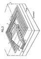
Les figures 5 et 6 représentent une tête planaire selon l'invention. Cette tête comporte, sur un substrat S, deux pôles magnétiques en couches minces 10 et 11 séparés par un entrefer 2.Figures 5 and 6 show a planar head according to the invention. This head comprises, on a substrate S, two magnetic poles in
Un circuit magnétique 1 portant des bobinages d'induction de champ magnétique 3 et 3' est situé de l'autre coté des pôles 10 et 11 par rapport au substrat et en vis à vis de ces pôles. Un flux F émis par les bobinages traverse le substrat S et se referme par les pôles 10 et 11.A magnetic circuit 1 carrying magnetic
Comme dans les exemples de réalisation précédents, l'entrefer 2 comporte un matériau supraconducteur imposant comme cela est représenté sur la figure 6 que la totalité du flux magnétique F créé par les bobines 3 et 3′ passe d'un pôle 10 à l'autre pôle 11 sans traverser l'entrefer 2.As in the previous exemplary embodiments, the
On va maintenant décrire l'application de l'invention à une tête magnétique pour enregistrement perpendiculaire.We will now describe the application of the invention to a magnetic head for perpendicular recording.
Cette application découle de la même idée inventive que celle des exemples de réalisation de l'invention décrits précédemment par le fait qu'il s'agit toujours de canaliser le flux magnétique émis par la tête vers le support d'enregistrement.This application stems from the same inventive idea as that of the embodiments of the invention described above by the fact that it is always a question of channeling the magnetic flux emitted by the head towards the recording medium.
Le caractérisée longitudinal ou perpendiculaire d'un enregistrement magnétique est plus déterminé par les propriétés du milieu d'enregistrement que par la tête elle-même. Aussi le type de tête représentée sur la figure 3 peut être utilisé dans les deux cas.The longitudinal or perpendicular characteristics of a magnetic recording is determined more by the properties of the recording medium than by the head itself. Also the type of head shown in Figure 3 can be used in both cases.
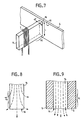
Dans certains cas il est toutefois souhaitable de disposer de têtes plus spécifiquement adaptés à l'enregistement perpendiculaire c'est à dire des têtes dans lesquelles la composante du champ magnétique perpendiculaire à la surface du support d'enregistrement est prépondérante par rapport à la composante longitudinale. Le principe de base utilisé à cette fin est de ne conserver qu'un seul pôle du circuit magnétique 1 dans la zone active de la tête, le reste du circuit pouvant se refermer sur le milieu d'enregistrement par un pôle dit auxiliaire ou pouvant être considéré comme se refermant à l'infini. Une telle tête d'enregistrement à pôle unique est représentée en figure 7.In some cases it is however desirable to have heads more specifically adapted to perpendicular recording, that is to say heads in which the component of the magnetic field perpendicular to the surface of the recording medium is preponderant with respect to the longitudinal component. . The basic principle used for this purpose is to keep only one pole of the magnetic circuit 1 in the active area of the head, the rest of the circuit can be closed on the recording medium by a so-called auxiliary pole or can be considered to be closed at infinity. Such a single pole recording head is shown in FIG. 7.
Dans ce type de tête, la résolution spatiale, c'est à dire la longueur d'onde minimale qui peut être lue par la tête, n'est plus déterminée par l'épaisseur de l'entrefer e mais par l'épaisseur du pôle principal. En théorie une résolution de l'ordre de 2e' est envisageable, mais cette limite ne peut être atteinte que pour une configuration idéale des lignes de champ qui ne peut être réalisée avec les matériaux courants parce que les lignes de champ magnétique , représentées en pointillés sur la figure 8, sortent du pôle avant la face 16 de l'extrémité.In this type of head, the spatial resolution, i.e. the minimum wavelength which can be read by the head, is no longer determined by the thickness of the air gap but by the thickness of the main pole. In theory a resolution of the order of 2e 'is possible, but this limit can only be reached for an ideal configuration of the field lines which cannot be achieved with current materials because the magnetic field lines, represented in dotted lines in Figure 8, exit the pole before the
Ce phénomène provient du fait que le milieu qui entoure le pôle présente, une perméabilité proche de l'unité.This phenomenon comes from the fact that the medium which surrounds the pole has a permeability close to unity.
Selon l'invention pour remédier à cet inconvénient on prévoit des moyens pour confiner le champ à l'intérieur du pôle en l'entourant d'un matériau supraconducteur 5 dont la perméabilité est nulle.According to the invention, to remedy this drawback, means are provided for confining the field inside the pole by surrounding it with a
La figure 9 représente un exemple de réalisation d'une telle tête magnétique . Le pôle 14 est enveloppé sur ces différentes faces, sauf la face 16 d'extrémité par un matériau de perméabilité nulle et plus particulièrement par un matériau supraconducteur 5. Ainsi, le champ magnétique est confiné dans le pôle magnétique 14. Il n'y a pas de champ de fuite par les parois latérales du pôle. La totalité du champ sort du pôle 14 par la face d'extrémité 16 comme cela est représenté en pointillés sur la figure 9.FIG. 9 represents an exemplary embodiment of such a magnetic head. The
L'efficacité d'une telle tête peut être amélioré en jouant sur la forme des éléments 1 et 5 pour concentrer le flux au niveau de la zone active.The efficiency of such a head can be improved by playing on the shape of
Ainsi sur l'exemple de réalisation représenté en figure 10, le pôle magnétique 14 comporte, à son extrémité 15, un rétrécissement permettant de concentrer le flux magnétique. Le matériau supraconducteur 5 épouse la forme de ce rétrécissement.Thus in the embodiment shown in FIG. 10, the
De plus, le matériau supraconducteur, selon cet exemple de réalisation enrobe la tête, c'est-à-dire le circuit magnétique 14 et le bobinage 3, excepté la face d'extrémité 16.In addition, the superconductive material, according to this exemplary embodiment, coats the head, that is to say the
Le circuit magnétique 14 peut également être refermé à l'aide d'un pôle auxiliaire sur le milieu d'enregistrement pourvu d'une sous-couche à forte perméabilité. Le pôle auxiliaire sera également pourvu d'une gaine en matériau supraconducteur canalisant le champ magnétique.The
Il convient de noter que l'amélioration des performances envisagées ne peut être obtenue que sous deux conditions :
- la profondeur de pénétration du champ magnétique dans le matériau supraconducteurest suffisamment faible,
- le champ critique du matériau supraconducteur est suffisamment élevé.It should be noted that the improvement in performance envisaged can only be obtained under two conditions:
- the depth of penetration of the magnetic field into the superconducting material is sufficiently small,
- the critical field of the superconducting material is sufficiently high.
Il est bien évident que la description qui précède n'a été faite qu'à titre d'exemple non limitatif. D'autres variantes peuvent être envisagées sans sortir du cadre de l'invention. Les exemples numériques n'ont été fournis que pour illustrer la description.It is obvious that the above description has been given only by way of nonlimiting example. Other variants can be envisaged without departing from the scope of the invention. Numerical examples have been provided only to illustrate the description.
Claims (11)
Applications Claiming Priority (2)
| Application Number | Priority Date | Filing Date | Title |
|---|---|---|---|
| FR8714825A FR2622341A1 (en) | 1987-10-27 | 1987-10-27 | RECORDING / READING MAGNETIC HEAD COMPRISING A SUPERCONDUCTING MATERIAL |
| FR8714825 | 1987-10-27 |
Publications (2)
| Publication Number | Publication Date |
|---|---|
| EP0314557A2 true EP0314557A2 (en) | 1989-05-03 |
| EP0314557A3 EP0314557A3 (en) | 1991-09-18 |
Family
ID=9356195
Family Applications (1)
| Application Number | Title | Priority Date | Filing Date |
|---|---|---|---|
| EP19880402673 Withdrawn EP0314557A3 (en) | 1987-10-27 | 1988-10-24 | Recording/reproducing magnetic head including a superconductor material |
Country Status (4)
| Country | Link |
|---|---|
| US (1) | US4979064A (en) |
| EP (1) | EP0314557A3 (en) |
| JP (1) | JPH01140410A (en) |
| FR (1) | FR2622341A1 (en) |
Cited By (1)
| Publication number | Priority date | Publication date | Assignee | Title |
|---|---|---|---|---|
| EP0367439A2 (en) * | 1988-11-01 | 1990-05-09 | Ampex Systems Corporation | Magnetic heads with superconductor shields |
Families Citing this family (7)
| Publication number | Priority date | Publication date | Assignee | Title |
|---|---|---|---|---|
| US5097243A (en) * | 1987-07-15 | 1992-03-17 | U.S. Philips Corp. | Thin-film transformer utilizing superconductive components |
| JPH0316007A (en) * | 1989-03-20 | 1991-01-24 | Hitachi Ltd | Magnetic recording device and magnetic head |
| FR2648607B1 (en) * | 1989-06-16 | 1995-12-15 | Thomson Csf | INTEGRATED MAGNETIC RECORDING HEAD |
| US5189580A (en) * | 1989-06-30 | 1993-02-23 | Ampex Corporation | Ultra small track width thin film magnetic transducer |
| US5198948A (en) * | 1990-12-05 | 1993-03-30 | Seagate Technology, Inc. | Shielded servo heads with improved passive noise cancellation |
| US6072669A (en) * | 1997-03-21 | 2000-06-06 | Indeck; Ronald S. | Thin film magnetic write head with preconditioning gap |
| FR2847747B1 (en) * | 2002-11-22 | 2005-02-18 | Thales Sa | ANALOGUE / DIGITAL CONVERTER FOR HYPERFREQUENCIES |
Citations (11)
| Publication number | Priority date | Publication date | Assignee | Title |
|---|---|---|---|---|
| DE588105C (en) * | 1932-09-01 | 1933-11-13 | Siemens & Halske Akt Ges | Magnet for recording vibrations on magnetizable writing carriers |
| US3098181A (en) * | 1960-08-29 | 1963-07-16 | Bell Telephone Labor Inc | Magnetic circuit using superconductor properties |
| US3214679A (en) * | 1964-04-13 | 1965-10-26 | Richard K Richards | Superconductive transformer system |
| DE1522971A1 (en) * | 1967-03-29 | 1969-10-30 | Altenkirch Karl Adolf | The subject of the invention is a method for improving the dynamics and the interfering distance of a magnetic sound head by means of an oblique arrangement of the gap and the use of diamagnetic substances |
| DE2100090A1 (en) * | 1971-01-02 | 1973-06-07 | Assmann Gmbh Wolfgang | MAGNETIC HEAD FOR RECORDING AND / OR PLAYBACK |
| JPS56145514A (en) * | 1980-04-14 | 1981-11-12 | Hitachi Ltd | Thin-film magnetic head |
| JPS57120221A (en) * | 1981-01-14 | 1982-07-27 | Seiko Epson Corp | Ring head for vertical magnetization recording and reproduction |
| JPS57183616A (en) * | 1981-05-08 | 1982-11-12 | Canon Inc | Magnetic head |
| JPS60154315A (en) * | 1984-01-20 | 1985-08-14 | Sanyo Electric Co Ltd | Magnetic head |
| EP0199522A2 (en) * | 1985-04-18 | 1986-10-29 | Matsushita Electric Industrial Co., Ltd. | Step-up type magnetic head |
| EP0300558A1 (en) * | 1987-07-15 | 1989-01-25 | Koninklijke Philips Electronics N.V. | Thin-film magnetic head including an inductive transducing element |
-
1987
- 1987-10-27 FR FR8714825A patent/FR2622341A1/en not_active Withdrawn
-
1988
- 1988-10-24 EP EP19880402673 patent/EP0314557A3/en not_active Withdrawn
- 1988-10-26 US US07/262,719 patent/US4979064A/en not_active Expired - Fee Related
- 1988-10-27 JP JP63271942A patent/JPH01140410A/en active Pending
Patent Citations (11)
| Publication number | Priority date | Publication date | Assignee | Title |
|---|---|---|---|---|
| DE588105C (en) * | 1932-09-01 | 1933-11-13 | Siemens & Halske Akt Ges | Magnet for recording vibrations on magnetizable writing carriers |
| US3098181A (en) * | 1960-08-29 | 1963-07-16 | Bell Telephone Labor Inc | Magnetic circuit using superconductor properties |
| US3214679A (en) * | 1964-04-13 | 1965-10-26 | Richard K Richards | Superconductive transformer system |
| DE1522971A1 (en) * | 1967-03-29 | 1969-10-30 | Altenkirch Karl Adolf | The subject of the invention is a method for improving the dynamics and the interfering distance of a magnetic sound head by means of an oblique arrangement of the gap and the use of diamagnetic substances |
| DE2100090A1 (en) * | 1971-01-02 | 1973-06-07 | Assmann Gmbh Wolfgang | MAGNETIC HEAD FOR RECORDING AND / OR PLAYBACK |
| JPS56145514A (en) * | 1980-04-14 | 1981-11-12 | Hitachi Ltd | Thin-film magnetic head |
| JPS57120221A (en) * | 1981-01-14 | 1982-07-27 | Seiko Epson Corp | Ring head for vertical magnetization recording and reproduction |
| JPS57183616A (en) * | 1981-05-08 | 1982-11-12 | Canon Inc | Magnetic head |
| JPS60154315A (en) * | 1984-01-20 | 1985-08-14 | Sanyo Electric Co Ltd | Magnetic head |
| EP0199522A2 (en) * | 1985-04-18 | 1986-10-29 | Matsushita Electric Industrial Co., Ltd. | Step-up type magnetic head |
| EP0300558A1 (en) * | 1987-07-15 | 1989-01-25 | Koninklijke Philips Electronics N.V. | Thin-film magnetic head including an inductive transducing element |
Non-Patent Citations (5)
| Title |
|---|
| IBM TECHNICAL DISCLOSURE BULLETIN, vol. 18, no. 1, juin 1975, pages 19-22, New York, US; L.T. ROMANKIW et al.: "Thin film and thin-film/ferrite hybrid magnetic heads" * |
| PATENT ABSTRACTS OF JAPAN, vol. 6, no. 217 (P-152)[1095], 30 octobre 1982; & JP-A-57 120 221 (SUWA SEIKOSHA K.K.) 27-07-1982 * |
| PATENT ABSTRACTS OF JAPAN, vol. 6, no. 27 (P-102)[905], 17 février 1982; & JP-A-56 145 514 (HITACHI SEISAKUSHO K.K.) 12-11-1981 * |
| PATENT ABSTRACTS OF JAPAN, vol. 7, no. 30 (P-173)[1175], 5 février 1983; & JP-A-57 183 616 (CANON K.K.) 12-11-1982 * |
| PATENT ABSTRACTS OF JAPAN, vol. 9, no. 329 (P-416)[2052], 24 décembre 1985; & JP-A-60 154 315 (SANYO DENKI K.K.) 14-08-1985 * |
Cited By (2)
| Publication number | Priority date | Publication date | Assignee | Title |
|---|---|---|---|---|
| EP0367439A2 (en) * | 1988-11-01 | 1990-05-09 | Ampex Systems Corporation | Magnetic heads with superconductor shields |
| EP0367439A3 (en) * | 1988-11-01 | 1991-11-13 | Ampex Systems Corporation | Magnetic heads with superconductor shields |
Also Published As
| Publication number | Publication date |
|---|---|
| EP0314557A3 (en) | 1991-09-18 |
| US4979064A (en) | 1990-12-18 |
| JPH01140410A (en) | 1989-06-01 |
| FR2622341A1 (en) | 1989-04-28 |
Similar Documents
| Publication | Publication Date | Title |
|---|---|---|
| EP0152325B1 (en) | Process for producing a coil for magnetic recording head and coil produced by that process | |
| EP0420755B1 (en) | Process for producing a magnetic recording head and head obtained by this process | |
| EP0153886B1 (en) | Process for the fabrication of a perpendicular recording magnetic head | |
| EP0652550B1 (en) | Read-out magnetic head with multilayer magnetoresistant element and concentrator and manufacturing method | |
| EP0417261B1 (en) | Magnetoresistant magnetic head for the longitudinal recording and method for making the same | |
| FR2612676A1 (en) | MAGNETIC READING HEAD FOR VERY LOW WIDTH TRACK AND METHOD FOR MANUFACTURING THE SAME | |
| EP0188944A1 (en) | System for perpendicular recording and method for fabricating a magnetic head | |
| EP0314557A2 (en) | Recording/reproducing magnetic head including a superconductor material | |
| EP0406362B1 (en) | Process for producing a reading/recording magnetic head and magnetic head obtained thereby | |
| EP0046697B1 (en) | Integrated magnetic transducer | |
| EP0035943B1 (en) | Magnetic head with variable track-width for writing or reading magnetic data | |
| EP0714090B1 (en) | Recording/reproduction magnetic head and production method | |
| EP0040994B1 (en) | Magnetic transducer having a variable largest dimension gap for playing back or recording information on a magnetic carrier | |
| FR2648941A1 (en) | MAGNETIC READING HEAD WITH HALL EFFECT | |
| EP0041409A1 (en) | Magnetic transducer for the playback or recording of information of a magnetic carrier | |
| EP0762388B1 (en) | Magnetic recording/reproducing head | |
| FR2585495A1 (en) | MAGNETIC RECORDING DEVICE WITH ROTATING HEAD | |
| EP0409673B1 (en) | Integrated magnetic recording head | |
| EP0132186B1 (en) | Highly integrated magnetic transducer for writing information on a magnetic carrier | |
| FR2761477A1 (en) | MAGNETORESISTOR MAGNETIC FIELD SENSOR | |
| EP0644528A1 (en) | Recording and reproducing magnetic head with magnetoresistant element compensated with respect to recording | |
| FR2500672A1 (en) | MAGNETIC THIN FILM HEAD AND MANUFACTURING METHOD THEREOF | |
| FR2633427A1 (en) | Magnetic recording/reading head using a superconducting material | |
| EP0203849B1 (en) | Magnetic bubble generator for a hybrid-technology bubble memory | |
| WO2000068959A1 (en) | Low pass cable |
Legal Events
| Date | Code | Title | Description |
|---|---|---|---|
| PUAI | Public reference made under article 153(3) epc to a published international application that has entered the european phase |
Free format text: ORIGINAL CODE: 0009012 |
|
| AK | Designated contracting states |
Kind code of ref document: A2 Designated state(s): DE GB IT NL |
|
| RAP3 | Party data changed (applicant data changed or rights of an application transferred) |
Owner name: THOMSON-CSF |
|
| PUAL | Search report despatched |
Free format text: ORIGINAL CODE: 0009013 |
|
| AK | Designated contracting states |
Kind code of ref document: A3 Designated state(s): DE GB IT NL |
|
| STAA | Information on the status of an ep patent application or granted ep patent |
Free format text: STATUS: THE APPLICATION IS DEEMED TO BE WITHDRAWN |
|
| 18D | Application deemed to be withdrawn |
Effective date: 19920319 |