EP0028177B1 - Integrated magnetic transducer - Google Patents
Integrated magnetic transducer Download PDFInfo
- Publication number
- EP0028177B1 EP0028177B1 EP80401422A EP80401422A EP0028177B1 EP 0028177 B1 EP0028177 B1 EP 0028177B1 EP 80401422 A EP80401422 A EP 80401422A EP 80401422 A EP80401422 A EP 80401422A EP 0028177 B1 EP0028177 B1 EP 0028177B1
- Authority
- EP
- European Patent Office
- Prior art keywords
- magnetic
- winding
- thin
- transducer
- layers
- Prior art date
- Legal status (The legal status is an assumption and is not a legal conclusion. Google has not performed a legal analysis and makes no representation as to the accuracy of the status listed.)
- Expired
Links
Images


Classifications
-
- G—PHYSICS
- G11—INFORMATION STORAGE
- G11B—INFORMATION STORAGE BASED ON RELATIVE MOVEMENT BETWEEN RECORD CARRIER AND TRANSDUCER
- G11B19/00—Driving, starting, stopping record carriers not specifically of filamentary or web form, or of supports therefor; Control thereof; Control of operating function ; Driving both disc and head
- G11B19/02—Control of operating function, e.g. switching from recording to reproducing
-
- G—PHYSICS
- G11—INFORMATION STORAGE
- G11B—INFORMATION STORAGE BASED ON RELATIVE MOVEMENT BETWEEN RECORD CARRIER AND TRANSDUCER
- G11B5/00—Recording by magnetisation or demagnetisation of a record carrier; Reproducing by magnetic means; Record carriers therefor
- G11B5/02—Recording, reproducing, or erasing methods; Read, write or erase circuits therefor
- G11B5/09—Digital recording
-
- G—PHYSICS
- G11—INFORMATION STORAGE
- G11B—INFORMATION STORAGE BASED ON RELATIVE MOVEMENT BETWEEN RECORD CARRIER AND TRANSDUCER
- G11B5/00—Recording by magnetisation or demagnetisation of a record carrier; Reproducing by magnetic means; Record carriers therefor
- G11B5/127—Structure or manufacture of heads, e.g. inductive
- G11B5/31—Structure or manufacture of heads, e.g. inductive using thin films
- G11B5/3109—Details
- G11B5/313—Disposition of layers
Definitions
- the present invention relates to an integrated magnetic transducer of the type described in the preamble of claim No. 1. It is particularly applicable to the reading and / or writing of the information contained on the magnetic recording media such as magnetic discs, rigid or flexible and the bands.
- the magnetic property used to record information on a magnetic support is defined for example, either by the absence or the presence of a magnetic induction or by the sign of this, or even by its direction.
- magnetic disks carry the information on circular concentric recording tracks which have a radial width not exceeding a few hundredths of a millimeter and generally cover most of their two faces.
- the magnetic tapes carry the information on tracks parallel to the length of the tape.
- transducers The most frequently used means, which make it possible either to record information on media such as discs or tapes, or to read it, or finally to carry out one or the other of these two functions, are called " magnetic transducers ". Generally one or more transducers are associated with a recording medium, the support moving past this nail. To simplify it will be assumed, in the following description, that a single transducer is associated with the same support.
- a magnetic transducer comprises a magnetic circuit around which a winding is arranged and which comprises an air gap. The latter is arranged at a very small distance from the surface of the support of the order of a few tenths of a micron.
- the winding includes electrical input and / or output wires.
- the winding is supplied with an electric current, the direction or duration of passage of which can be varied.
- the support is thus subjected to the magnetic field of variable intensity and direction created by the transducer in the immediate vicinity of its air gap (a few tenths of a micron thereof), which creates a succession of small areas on each track of the support.
- magnetic whose dimension is of the order of that of the air gap, and which have magnetic inductions in opposite directions.
- the transducer associated with it delivers electrical signals via its electrical input and / or output wires, signals sent to circuits. reading electronics associated with transducers.
- transducers of increasingly smaller dimensions ((for example, with air gaps whose dimensions are of the order of a micron), such transducers being for example, manufactured by the Compagnie Internationale pour l'Informatique CII-Honeywell Bull and described in French patents FR-A-2,063,693 filed on October 28, 1969 by the Compagnie Internationale pour l'Informatique and the Commissariat à atomic energy under the title: Integrated magnetic head and process for manufacturing the said head "and FR-A-2,209,154 filed on July 03, 1972 by the International Company for Computing under the title:” Advanced magnetic transducers and their manufacturing process. "
- the magnetic recording medium associated with the transducer runs past it perpendicular to the plane of the two magnetic layers, that is to say perpendicular to the length of the air gap.
- any magnetic domain of a track of the support opposite which the transducer is arranged passes successively over time, in line with the first magnetic layer called “pole piece upstream” and the second called “pole piece downstream”. It is also said that said domain successively meets the upstream and downstream pole pieces and by extension, that the support successively meets said upstream and downstream parts.
- the downstream pole piece which defines the nature of the information recorded on the support, that is to say in particular the direction and the modulus of the magnetic induction in each of the domains created on this support.
- each of these is successively subjected, over time, to the magnetic field created by the upstream pole piece in the immediate vicinity of its surface, on the side of the air gap of the transducer and to the field created by the downstream pole piece, which therefore acts last on said area.
- downstream pole piece of an integrated transducer is that which is deposited on the substrate.
- the winding of an integrated transducer comprises two identical windings (that is to say having the same number of turns) which have a common electrical point.
- the first winding DC is the one whose thin conductive layers are closest to the downstream pole piece
- the second winding DA is the one whose thin conductive layers are the most distant, point D being the electrical point common to the two windings .
- the mutual magnetic coupling coefficient of the first DC winding with the downstream pole piece also called mutual inductance coefficient
- the mutual magnetic coupling coefficient of the second winding DA with it is greater than the mutual magnetic coupling coefficient of the second winding DA with it.
- the magnetic induction in the recording medium is asymmetrical.
- This asymmetry of the signal has drawbacks when it is used by the electronic circuits associated with the transducer, and can lead to errors in determining the value of the information represented by each of these pulses.
- This risk of error is all the more important as the density of the information along each track of the support is greater, (in current current practice, supports are used more and more frequently recording at high information density), that is to say when the number of elementary magnetic domains per unit of length measured according to the circumference of the track is greater.
- the solution adopted in the magnetic transducer described in the Japanese application consists in that the sum of the distances ⁇ a of all the points of the first conductor with respect to the downstream pole piece is equal to the sum of the distances of all the points Eb of the second transducer with respect to this same downstream pole piece.
- the present invention overcomes the drawbacks of the solution adopted for the integrated magnetic transducer described in the Japanese patent application, by making the vast majority of integrated magnetic transducers comprising a plurality of turns usable even if they have successive thin conductive layers. short-circuited, while allowing the magnetic fluxes of the first and second windings to be equalized through the downstream pole piece.
- FIGS. 1 a, 1 b, 1 c, 1d the integrated magnetic transducers according to the prior art, illustrated by FIGS. 1 a, 1 b, 1 c, 1d and on the other hand on the disadvantages which these present as well as with the writing than with the reading of the information, illustrated by FIGS. 2 and 3.
- an integrated magnetic transducer comprises a magnetic circuit formed by two magnetic polar pieces in thin layers PP, and PP 2 entirely superimposed and magnetically coupled to a BOB coil. .
- the pole pieces PP, and PP are magnetostatically coupled together at a first end EXT and form the air gap G at another end.
- the pole piece PP is deposited on a SUBS substrate as can be seen in Figure 1d.
- the TMA transducer is shown arranged opposite a support SM recording of which only a part has been shown for simplicity.
- This support comprises a plurality of recording tracks of which only the track p is shown, which comprises a plurality of elementary magnetic domains of which only three are represented, namely the domains A ,, A 2 , A 3 in this same figure 1 c and five, namely, A 1 to A 5 in Figure 1 d.
- the medium SM is for example a magnetic disk belonging to a disk memory. We know that disk memories are more and more used in information processing systems because of their storage capacity and the relatively short time taken by write and / or read transducers to access information. contained at any point on the disc from the moment it receives from said processing system, the order to access this information.
- the support SM scrolling in the direction of the arrow F, the pole piece PP 1 is the downstream pole piece.
- the pole pieces PP, and PP 2 generally consist of a set of several thin magnetic layers and thin insulating layers filled with each magnetic layer being separated from the neighboring layer by an insulating layer.
- the assembly thus defined, whether it comprises one or more magnetic thin layers is usually designated by the general name of "magnetic thin layer".
- the BOB winding is formed by a succession of thin conductive and insulating layers used in a direction perpendicular to the plane of the magnetic pole pieces in thin layers PP 1 and PP 2 , part of the conductive and insulating layers being flush with the gap G. insulating layers are arranged between the conductive layers.
- FIG. 1 d only ten conductive layers, namely CO 1 to CO 10 , have been shown, in the embodiment shown in this same figure. These conductive layers which have the same shape and are of different dimensions are interconnected by connecting conductive elements, not shown, to simplify Figures 1 to 1 d.
- the BOB winding comprises two windings E 1 and E 2 having a common point D, their respective ends being C and A.
- a disk memory comprising several transducers associated with several disks, all is selected transducer which we want it to perform read operations, by sending an electrical selection pulse to its midpoint D.
- the BOB winding comprises three output conductors, namely the conductors C 1 , C 2 , C 3 , (see FIG. 1c) which are connected to the electronic reading and / or writing circuits of the disk memory containing the disk SM.
- each of the windings E, and E 2 by a rectangular current pulse.
- the winding E 1 is for example supplied by a negative pulse, while the winding E 2 is supplied by a positive pulse, with the same module as the negative pulse.
- the distribution of the magnetic induction along a recording track of the disc SM is then that indicated by FIG. 2 where the variation of the induction has been represented in the six neighboring elementary domains A 1 to A 6 .
- the domains A 1 , A 3 , A 5 are recorded when the winding E 2 is supplied by a positive current pulse while the domains A 2 , A 4 , A 6 are recorded when the winding E ,, is traversed by the negative current pulse.
- the magnetic coupling of the winding E 1 with the downstream pole piece PP 1 being greater than that of the winding E 2 with this same piece, it results in particular that the module B 2 of the magnetic induction in the domains A 1 , A 3 , A 5 is less than the module B 1 of the induction in the areas A 2 , A 4 , A s : along a recording track, the magnetic induction also called "writing induction” or writing field "is asymmetric.
- t d (t 3 -t 2 ) of the falling edges FD 1 and FD 3 of these same pulses.
- the TMI transducer is such that the number of turns of the winding E 1 is less than the number of turns of winding E 2 : this compensates for the fact that the magnetic coupling of E 1 with the downstream pole piece PP, is greater than the coupling of E 2 with the latter.
- the same references designate the same elements in FIGS. 4a, 4b, 5, 6a, 6b, on the one hand, and in FIGS. 1 a and 1 d, on the other hand.
- the quantities (I 1 ⁇ M i1 ) and (I 2 ⁇ M j2 ) respectively represent the magnetic fluxes created by the passage of the currents I 1 and I 2 in each of the conductive layers CO i and CO j , through the downstream pole piece PP 1 . It is also said, for the sake of abbreviation, that these quantities represent the magnetic fluxes of each of the conductive layers CO i and CO j through the downstream pole piece.
- ⁇ PP is therefore the sum of the magnetic fluxes of each of the conductive layers which compose it and represents the magnetic flux created by the passage of current in this winding, through the part polar avaL: we also say, for short, that this is the magnetic flux created by this winding, through the downstream pole piece.
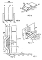
- FIG. 4b shows a perspective three-quarter view of a first embodiment TMI, of a transducer according to the invention, where the winding E 1 has four turns and the winding E 2 has seven turns.
- FIG. 5 is a block diagram of a second embodiment TMI 2 according to the invention comprising four windings E 1 , E 2 , E 3 , E 4 the winding E 1 being the winding closest to the part downstream polar while winding E4 is the most distant. Their respective number of turns is N 1 , N 2 , N 3 , N 4 with N 1 ⁇ N 2 ⁇ N 3 ⁇ N 4 .
- Winding E 1 and winding E 2 have a common electrical point F
- winding E 2 and winding E 3 have a common electrical point E
- winding E 3 and winding E4 have an electrical point common of.
- E ' 1 can be constituted by the winding E 1 traversed by the same current I 1 )
- E' 2 is then constituted by the association in series of the windings E 2 , E 3 , E4 (traversed by the same current I 2 ): in this case, the current generator is connected between the electrical point F and the end A of the winding BOB, the electrical points D 'and E not being connected to the generator.
- E “ 1 can be constituted by associating in series the windings E 1 and E 2 traversed by I 1 ), E" 2 then being constituted by the association in series of the windings E 3 and E 4 (traversed by 1 2 ): in in this case, the electrical points D 'and F are not connected to the current generator.
- the quantity ⁇ PP represents the magnetic flux of the windings E ' 1 and E' 2 , through the pole pieces PP 1 , while the quantity ⁇ "PP 1 represents the magnetic flux of the windings E" 1 and E " 2 through this same PP downstream pole piece.
- FIG. 6 shows the curve of variation of the magnetic induction in six elementary magnetic domains A 1 to A 6 successive of a track p of the magnetic disc SM. These domains are recorded by any of the TMI 1 , TMI 2 and TMI 3 transducers according to the invention.
- the module identical B 3 of positive inductions in domains A 1 , A 3 and A 5 is equal to the identical module B 4 of negative inductions in domains A 2 , A 4 and A 6 .
Description
La présente invention concerne un transducteur magnétique intégré du type décrit dans le préambule de la revendication n° 1. Elle est notamment applicable à la lecture et/ou l'écriture des informations contenues sur les supports magnétiques d'enregistrement tels que les disques magnétiques, rigides ou souples et les bandes.The present invention relates to an integrated magnetic transducer of the type described in the preamble of claim No. 1. It is particularly applicable to the reading and / or writing of the information contained on the magnetic recording media such as magnetic discs, rigid or flexible and the bands.
On sait que, pour enregistrer (on dit encore écrire) des informations sur un support magnétique d'enregistrement, on crée sur (ou dans) ce support, en une pluralité d'endroits parfaitement déterminés de celui-ci, au moins une modification de l'une de ses propiétés magnétiques, ce qui se traduit par au moins une variation de la grandeur physique qui caractérise ladite propriété. La lecture de ces informations s'effectue en détectant lesdites modifications et en transformant la variation de la grandeur physique définie plus haut en une variation d'une autre grandeur physique qui le plus souvent est la variation de la tension ou du courant d'un signal électrique.We know that, to record (we also say write) information on a magnetic recording medium, we create on (or in) this medium, in a plurality of perfectly determined places thereof, at least one modification of one of its magnetic properties, which results in at least one variation of the physical quantity which characterizes said property. The reading of this information is carried out by detecting said modifications and by transforming the variation of the physical quantity defined above into a variation of another physical quantity which most often is the variation of the voltage or of the current of a signal. electric.
La propriété magnétique utilisée pour enregistrer des informations sur un support magnétique est définie par exemple, soit par l'absence ou la présence d'une induction magnétique soit par le signe de celle-ci, soit encore par sa direction.The magnetic property used to record information on a magnetic support is defined for example, either by the absence or the presence of a magnetic induction or by the sign of this, or even by its direction.
On sait que les disques magnétiques portent les informations sur des pistes d'enregistrement concentriques circulaires qui ont une largeur radiale n'excédant pas quelques centièmes de millimètre et couvrent généralement la majeure partie de leurs deux faces.It is known that magnetic disks carry the information on circular concentric recording tracks which have a radial width not exceeding a few hundredths of a millimeter and generally cover most of their two faces.
Les bandes magnétiques portent les informations sur des pistes parallèles à la longueur de la bande.The magnetic tapes carry the information on tracks parallel to the length of the tape.
Les moyens les plus fréquemment utilisés, qui permettent soit d'enregistrer les informations sur des supports tels que les disques ou les bandes, soit de les lire, soit enfin de réaliser l'une ou l'autre de ces deux fonctions, sont appelés "transducteurs magnétiques". Généralement on associe à un support d'enregistrement un ou plusieurs transducteurs, le support défilant devant celui-clou ceux-ci. Pour simplifier on supposera, dans la suite de la description, qu'un seul transducteur est associé à un même support.The most frequently used means, which make it possible either to record information on media such as discs or tapes, or to read it, or finally to carry out one or the other of these two functions, are called " magnetic transducers ". Generally one or more transducers are associated with a recording medium, the support moving past this nail. To simplify it will be assumed, in the following description, that a single transducer is associated with the same support.
Un transducteur magnétique comprend un circuit magnétique autour duquel est disposé un enroulement et qui comporte un entrefer. Ce dernier est disposé à une distance très faible de la surface du support de l'ordre de quelques dixièmes de micron.A magnetic transducer comprises a magnetic circuit around which a winding is arranged and which comprises an air gap. The latter is arranged at a very small distance from the surface of the support of the order of a few tenths of a micron.
L'enroulement comprend des fils électriques d'entrée et/ou sortie.The winding includes electrical input and / or output wires.
Pour enregistrer les informations sur le support associé au transducteur, on alimente l'enroulement par un courant électrique dont on peut faire varier le sens ou la durée de passage dans celui-ci. Le support est ainsi soumis au champ magnétique d'intensité et de sens variable crée par le transducteur au voisinage immédiat de son entrefer (à quelques dixièmes de micron de celui-ci), ce qui crée sur chaque piste du support une succession de petits domaines magnétiques, dont la dimension est de l'ordre de celle de l'entrefer, et qui ont des inductions magnétiques de sens opposé. Ces domaines, également appelés "domaines magnétiques élémentaires", sont répartis sur toute la longueur de la piste.To record the information on the support associated with the transducer, the winding is supplied with an electric current, the direction or duration of passage of which can be varied. The support is thus subjected to the magnetic field of variable intensity and direction created by the transducer in the immediate vicinity of its air gap (a few tenths of a micron thereof), which creates a succession of small areas on each track of the support. magnetic, whose dimension is of the order of that of the air gap, and which have magnetic inductions in opposite directions. These domains, also called "elementary magnetic domains", are distributed over the entire length of the track.
Inversement, lorsque les informations d'un support donné défilent devant l'entrefer du transducteur qui lui est associé, celui-ci délivre des signaux électriques par l'intermédiaire de ses fils électriques d'entrée et/ou sortie, signaux envoyés à des circuits électroniques de lecture associés aux transducteurs.Conversely, when the information from a given medium passes in front of the air gap of the transducer associated with it, the latter delivers electrical signals via its electrical input and / or output wires, signals sent to circuits. reading electronics associated with transducers.
La tendance actuelle du développement des transducteurs magnétiques est de produire, selon les techniques de fabrication des circuits intégrés, des transducteurs de dimension de plus en plus faibles, (par exemple, avec des entrefers dont les dimensions sont de l'ordre du micron), de tels transducteurs étant par exemple, fabriqués par la Compagnie Internationale pour L'Informatique CII-Honeywell Bull et décrits dans les brevets français FR-A-2.063.693 déposé le 28 Octobre 1969 par la Compagnie Internationale pour l'Informatique et le Commisariat à l'énergie atomique sous le titre: Tête magnétique intégrée et procédé de fabrication de la dite tête" et FR-A-2.209,154 déposé le 03 juillet 1972 par la Compagnie Internationale pour l'Informatique sous le titre: "Transducteurs magnétiques perfectionnés et leur procédé de fabrication".The current trend in the development of magnetic transducers is to produce, according to the manufacturing techniques of integrated circuits, transducers of increasingly smaller dimensions ((for example, with air gaps whose dimensions are of the order of a micron), such transducers being for example, manufactured by the Compagnie Internationale pour l'Informatique CII-Honeywell Bull and described in French patents FR-A-2,063,693 filed on October 28, 1969 by the Compagnie Internationale pour l'Informatique and the Commissariat à atomic energy under the title: Integrated magnetic head and process for manufacturing the said head "and FR-A-2,209,154 filed on July 03, 1972 by the International Company for Computing under the title:" Advanced magnetic transducers and their manufacturing process. "
Un tel transducteur connu comprend d'une part:
- a)-un circuit magnétique formé de deux couches minces réunies à une extrémité de manière à ce qu'elles soient couplées magnétiquement, et disposées à l'autre extrémité voisine du support d'enregistrement associé au transducteur, de façon à former un entrefer (l'entrefer est situé habituellement à quelques dixièmes de microns du support). L'entrefer de forme sensiblement rectangulaire à une longueur très supérieure à la largeur, voisine de la largeur des pistes du support. Le support est sensiblement perpendiculaire auxdites couches qui constituent les pièces polaires du transducteur. L'une des deux couches minces magnétiques est disposée sur un substrat en matière isolante.
- b)-d'autre part, un bobinage électrique formé, entre lesdites couches minces magnétiques, de couches minces conductrices qui sont superposées dans une direction perpendiculaire au plan desdites couches minces magnétiques, de telle sorte que ces dernières forment une enveloppe contenant les couches conductrices séparées les unes des autres par des couches minces électriquement isolantes (on rappelle que l'on désigne habituellement sous le nom de couches minces des couches dont l'épaisseur est de l'ordre de quelques angstrôms à quelques microns).
- a) -a magnetic circuit formed by two thin layers joined at one end so that they are magnetically coupled, and arranged at the other close end of the recording medium associated with the transducer, so as to form an air gap ( the air gap is usually located a few tenths of a micron from the support). The air gap of substantially rectangular shape at a length much greater than the width, close to the width of the tracks of the support. The support is substantially perpendicular to said layers which constitute the pole pieces of the transducer. One of the two thin magnetic layers is placed on a substrate made of insulating material.
- b) on the other hand, an electric coil formed between said magnetic thin layers of conductive thin layers which are superimposed in a direction perpendicular to the plane of said magnetic thin layers, so that the latter form an envelope containing the conductive layers separated from each other by electrically insulating thin layers (it should be recalled that layers whose thickness is of the order of a few angstroms to a few microns are usually designated by the name of thin layers).
Le support d'enregistrement magnétique associé auThe magnetic recording medium associated with the
Le support d'enregistrement magnétique associé au transducteur défile devant celui-ci perpendiculairement au plan des deux couches magnétiques, c'est-à-dire perpendiculairement à la longueur de l'entrefer. Lors de ce défilement, tout domaine magnétique d'une piste du support en regard de laquelle le transducteur est disposé, passe successivement dans le temps, au droit de la première couche magnétique appelée "pièce polaire amont" et de la seconde appelée "pièce polaire aval". On dit également que ledit domaine rencontre successivement les pièces polaires amont et aval et par extension, que le support rencontre successivement lesdites pièces amont et aval.The magnetic recording medium associated with the transducer runs past it perpendicular to the plane of the two magnetic layers, that is to say perpendicular to the length of the air gap. During this scrolling, any magnetic domain of a track of the support opposite which the transducer is arranged, passes successively over time, in line with the first magnetic layer called "pole piece upstream" and the second called "pole piece downstream". It is also said that said domain successively meets the upstream and downstream pole pieces and by extension, that the support successively meets said upstream and downstream parts.
De ce fait il est clair, que des deux pièces polaires, c'est la pièce polaire aval qui définit la nature des informations enregistrées sur le support, c'est-à-dire notamment le sens et le module de l'induction magnétique dans chacun des domaines crées sur ce support. En effet, lorsque ce dernier défile devant le transducteur, chacun de ceux-ci est soumis successivement, dans le temps au champ magnétique créé par la pièce polaire amont au voisinage immédiat de sa surface, du côté de l'entrefer du transducteur et au champ créé par la pièce polaire aval, qui agit donc en dernier sur ledit domaine.Therefore it is clear, that of the two pole pieces, it is the downstream pole piece which defines the nature of the information recorded on the support, that is to say in particular the direction and the modulus of the magnetic induction in each of the domains created on this support. In fact, when the latter passes in front of the transducer, each of these is successively subjected, over time, to the magnetic field created by the upstream pole piece in the immediate vicinity of its surface, on the side of the air gap of the transducer and to the field created by the downstream pole piece, which therefore acts last on said area.
En d'autres termes, on peut dire, que, lors de l'enregistrement des informations, seule la pièce polaire aval laisse son "empreinte de champ" sur le support.In other words, it can be said that, during the recording of the information, only the downstream pole piece leaves its "field imprint" on the support.
De préférence la pièce polaire aval d'un transducteur intégré est celle qui est déposée sur le substrat.Preferably the downstream pole piece of an integrated transducer is that which is deposited on the substrate.
Dans la pratique courante, le bobinage d'un transducteur intégré comprend deux enroulements, identiques (c'est-à-dire ayant le même nombre de tours) qui ont un point électrique commun. Le premier enroulement DC est celui dont les couches conductrices minces sont les plus proches de la pièce polaire aval, alors que le second enroulement DA est celui dont les couches conductrices minces sont les plus éloignées, le point D étant le point électrique commun aux deux enroulements. Il en résulte que le coefficient de couplage, magnétique mutuel du premier enroulement DC avec la pièce polaire aval (également appelé coefficient d'inductance mutuelle) est supérieur au coefficient de couplage magnétique mutuel du second enroulement DA avec cell-ci.In current practice, the winding of an integrated transducer comprises two identical windings (that is to say having the same number of turns) which have a common electrical point. The first winding DC is the one whose thin conductive layers are closest to the downstream pole piece, while the second winding DA is the one whose thin conductive layers are the most distant, point D being the electrical point common to the two windings . As a result, the mutual magnetic coupling coefficient of the first DC winding with the downstream pole piece (also called mutual inductance coefficient) is greater than the mutual magnetic coupling coefficient of the second winding DA with it.
Cela entraîne les conséquences suivantes:
- -on sait que pour enregistrer deux domaines élementaires successifs sur une piste du support d'enregistrement on alimente successivement le premier enroulement DC par une impulsion de tension et/ou courant, par exemple positive, le second enroulement DA n'étant alors pas alimenté) et le second enroulement par une impulsion de tension et/ou courant par exemple négative (le premier enroulement DC n'étant alors pas alimenté), les amplitudes des impulsions négative et positive étant égales en valeur absolue. Les coefficients de couplage magnétique mutuels des enroulements DC, DA avec la pièce polaire aval étant différents, il en résulte, notamment, que les modules des inductions magnétiques créés par le transducteur à l'intérieur des deux domaines élémentaires successifs enregistrés sont différents: Le module de l'induction magnétique dans le domaine élémentaire enregistré par le passage du courant électrique dans l'enroulement DC est supérieur au module de l'induction magnétique dans le domaine élementaire enregistré lors du passage du courant électrique dans l'enroulement DA, puisque le couplage magnétique de l'enroulement BC avec la pièce polaire aval est supérieur à celui de l'enroulement DC avec cette même pièce.
- -it is known that to record two successive elementary domains on a track of the recording medium, the first DC winding is successively supplied by a voltage and / or current pulse, for example positive, the second DA winding then not being supplied) and the second winding by a voltage and / or current pulse, for example negative (the first DC winding then not being supplied), the amplitudes of the negative and positive pulses being equal in absolute value. The mutual magnetic coupling coefficients of the windings DC, DA with the downstream pole piece being different, it follows, in particular, that the modules of the magnetic inductions created by the transducer inside the two recorded successive elementary domains are different: The module of the magnetic induction in the elementary domain recorded by the passage of the electric current in the DC winding is greater than the module of the magnetic induction in the elementary domain recorded during the passage of the electric current in the DA winding, since the coupling magnetic of the BC winding with the downstream pole piece is greater than that of the DC winding with this same piece.
En d'autres termes, la courbe représentative d'induction magnétique mesurée le long d'une piste du support est asymétrique par rapport à l'axe d'ordonnée B=O où B est l'induction magnétique.In other words, the representative magnetic induction curve measured along a track of the support is asymmetrical with respect to the ordinate axis B = O where B is the magnetic induction.
Elle se présente comme une succession d'impulsions, d'induction magnétique, alternativement négatives et positives, le module des impulsions négatives étant différent du module des impulsions positives.It appears as a succession of pulses, of magnetic induction, alternately negative and positive, the module of negative pulses being different from the module of positive pulses.
Par abus de langage, on dit encore que l'induction magnétique dans le support d'enregistrement est asymétrique.By abuse of language, it is also said that the magnetic induction in the recording medium is asymmetrical.
Lorsque deux domaines magnétiques élementaires successifs d'une piste du support défilent devant le transducteur, celui-ci délivre une impulsion électrique telle qui l'intervalle de temps séparant l'instant t, où sa tension est nulle de l'instant t2 où sa tension est maximale est sensiblement différent de l'intervalle de temps séparant ce même instant t2 de l'instant t3 où sa tension retombe à zéro. Il est clair qu'il en est de même pour chaque impulsion électrique délivrée par le transducteur lorsque touts les domaines élémentaires d'une piste défilent devant lui. On dit alors que le signal de lecture des informations d'une piste est asymétrique en fonction du temps.When two successive elementary magnetic domains of a track of the support pass in front of the transducer, the latter delivers an electric pulse such that the time interval separating the instant t, where its voltage is zero from the instant t 2 where its maximum voltage is significantly different from the time interval separating this same instant t 2 from instant t 3 where its voltage drops to zero. It is clear that the same is true for each electrical pulse delivered by the transducer when all the elementary domains of a track pass in front of it. It is then said that the signal for reading the information of a track is asymmetrical as a function of time.
Cette asymétrie du signal présente des inconvénients lors de l'exploitation de celui-ci par les circuits électroniques associés au transducteur, et peut entraîner des erreurs dans la détermination de la valeur des informations que représente chacune de ces impulsions. Ce risque d'erreur est d'autant plus important que la densité des informations le long de chaque piste du support est plus grande, (dans la pratique courante actuelle, on utilise de plus en plus fréquemment des supports d'enregistrement à forte densité d'informations), c'est-à-dire lorsque le nombre de domaines magnétiques élémentaires par unité de longueur mesurée selon la circonférence de la piste est plus grand.This asymmetry of the signal has drawbacks when it is used by the electronic circuits associated with the transducer, and can lead to errors in determining the value of the information represented by each of these pulses. This risk of error is all the more important as the density of the information along each track of the support is greater, (in current current practice, supports are used more and more frequently recording at high information density), that is to say when the number of elementary magnetic domains per unit of length measured according to the circumference of the track is greater.
Dans la pratique courante, on connait des solutions permettant de remédier à ces inconvénients. Celles-ci cherchent à résoudre le problème suivant à savoir égaliser les flux magnétiques créés par chacun des deux enroulements constituant le bobinage à travers la pièce polaire aval.In current practice, solutions are known which make it possible to remedy these drawbacks. These seek to solve the following problem, namely to equalize the magnetic fluxes created by each of the two windings constituting the winding through the downstream pole piece.
Une telle solution est par exemple décrite dans la demande brevet japonaise JPA-5.398.811, publiée le 29 Août 1968, et dont le résumé a été publié dans le Patent Abstracts of Japan, volume 2 N° 133 du 8 Novembre 1978, page 8012 E 78. Cette demande de brevet japonaise décrit un transducteur magnétique intégré comportant une première pièce polaire qu'on considère comme la pièce polaire aval et une seconde pièce polaire, réalisées en couches minces et entre lesquelles est disposé un bobinage formé de deux demi- bobinages constitué chacun d'un seul conducteur en couches minces. Pour simplifier, ces deux conducteurs seront appelés respectivement premier conducteur et second conducteur.Such a solution is for example described in Japanese patent application JPA-5,398,811, published on August 29, 1968, the summary of which was published in the Patent Abstracts of Japan, volume 2 N ° 133 of November 8, 1978, page 8012 E 78. This Japanese patent application describes an integrated magnetic transducer comprising a first pole piece which is considered to be the downstream pole piece and a second pole piece, produced in thin layers and between which is a coil formed by two half-coils. each consisting of a single conductor in thin layers. For simplicity, these two conductors will be called respectively first conductor and second conductor.
Si l'on appelle a la distance d'un point donné du premier conducteur par rapport à la première pièce polaire aval, et b la distance d'un point donné du second conducteur par rapport à cette même pièce polaire aval, la solution adoptée dans le transducteur magnétique décrit dans la demande japonaise consiste en ce que la somme des distances Σa de tous les points de premier conducteur par rapport à la pièce polaire aval est égale à la somme des distances de tous les points Eb du second transducteur par rapport à cette même pièce polaire aval.If we call a the distance from a given point of the first conductor with respect to the first downstream pole piece, and b the distance from a given point of the second conductor with respect to this same downstream pole piece, the solution adopted in the magnetic transducer described in the Japanese application consists in that the sum of the distances Σa of all the points of the first conductor with respect to the downstream pole piece is equal to the sum of the distances of all the points Eb of the second transducer with respect to this same downstream pole piece.
Il en résulte que les deux conducteurs étant parcourus par le même courant I, le flux magnétique créé par le passage de ce courant dans le second conducteur à travers la pièce polaire aval est égal au flux magnétique créé par le passage du même courant I dans le premier conducteur à travers cette même pièce polaire aval.It follows that the two conductors being traversed by the same current I, the magnetic flux created by the passage of this current in the second conductor through the downstream pole piece is equal to the magnetic flux created by the passage of the same current I in the first conductor through this same downstream pole piece.
En conclusion, on voit que dans ce transducteur magnétique intégré, qui comporte seulement deux tours de bobinage, chaque tour constituant un demi-bobinage, les flux magnétiques créés par chacun des deux conducteurs à travers la pièce polaire aval sont égaux, cela étant obtenu en agissant sur la forme géométrique de chaque tour (de chaque conducteur) et la localisation de chacun des points de celui-ci par rapport à la pièce polaire aval.In conclusion, we see that in this integrated magnetic transducer, which has only two winding turns, each turn constituting a half-winding, the magnetic fluxes created by each of the two conductors through the downstream pole piece are equal, this being obtained by acting on the geometric shape of each turn (of each conductor) and the location of each of the points thereof relative to the downstream pole piece.
La solution adoptée dans le transducteur magnétique intégré décrite dans la demande de brevet japonaise précitée présente l'inconvénient de ne pas convenir pour des transducters magnétiques intégrés dont les deux enroulements comportent une pluralité de tours. Ainsi, il est extrêmement fréquent que les transducteurs magnétiques intégrés utilisés dans la pratique courante comportent des bobinages ayant de l'ordre de 10 à 20 tours. On voit en effet que, dans ce cas, l'adoption de la solution de la demande de brevet japonaise précitée est pratiquement impossible puisqu'il serait extrêmement difficile et compliqué technologiquement d'égaliser la somme des distances de tous les points de chaque conducteur de chaque enroulement par rapport à la pièce polaire aval.The solution adopted in the integrated magnetic transducer described in the aforementioned Japanese patent application has the drawback of not being suitable for integrated magnetic transducters, the two windings of which comprise a plurality of turns. Thus, it is extremely common for the integrated magnetic transducers used in current practice to have windings having the order of 10 to 20 turns. It can be seen that, in this case, the adoption of the solution of the aforementioned Japanese patent application is practically impossible since it would be extremely difficult and technologically complicated to equalize the sum of the distances from all the points of each conductor of each winding with respect to the downstream pole piece.
De plus, on constate dans' la pratique courante, que pour des raisons teéhnologiques de fabrication, il arrive fréquemment que deux couches conductrices successives du second enroulement DA d'un transducteur magnétique intégré dont le bobinage comporte plusieurs tours, soient en court circuit. On montre que la probabilité d'avoir des court-circuits entre couches conductrices voisines ou de mauvaises isolations varient proportionnellement au carré du nombre de tours; par conséquent plus il y a de tours, plus la probabilité d'avoir des courts-circuits est grande. Enfin, on observe que la probabilité d'existence des court-circuits ou de mauvaises isolations est beaucoup plus grande pour le second enroulement DA que pour le premier enroulement DC. Cela provient du fait que pour des raisons technologiques de fabrication, il est plus difficile d'empiler des couches minces conductrices les unes sur les autres pour le second enroulement que pour le premier puisque chacune des couches conductrices et chacune des couches isolantes de ce second enroulement est déposée, dans le temps, après les couches conductrices et les couches isolantes du premier bobinage.In addition, it is found in 'current practice, that for technological reasons of manufacture, it frequently happens that two successive conductive layers of the second winding DA of an integrated magnetic transducer whose winding comprises several turns, are in short circuit. We show that the probability of having short circuits between neighboring conductive layers or poor insulation varies proportionally to the square of the number of turns; therefore the more laps there are, the greater the probability of having short circuits. Finally, we observe that the probability of existence of short circuits or bad insulation is much greater for the second winding DA than for the first winding DC. This is due to the fact that for technological manufacturing reasons, it is more difficult to stack thin conductive layers on top of each other for the second winding than for the first since each of the conductive layers and each of the insulating layers of this second winding is deposited, in time, after the conductive layers and the insulating layers of the first winding.
Il est bien évident qu'une fois la structure de transducteur intégré réalisée, on ne peut plus la modifier dans le cas où des court-circuits apparaissent entre des couches conductrices minces successives.It is obvious that once the integrated transducer structure has been produced, it can no longer be modified in the event that short circuits appear between successive thin conductive layers.
La présente invention permet de remédier aux inconvénients de la solution adoptée pour le transducteur magnétique intégré décrit dans la demande de brevet japonaise, en rendant la grande majorité des transducteurs magnétiques intégrés comportant une pluralité de tours utilisables même s'ils possèdent des couches conductrices minces successives en court-circuit, tout en permettant d'égaliser les flux magnétiques du premier et du second enroulement à travers la pièce polaire aval.The present invention overcomes the drawbacks of the solution adopted for the integrated magnetic transducer described in the Japanese patent application, by making the vast majority of integrated magnetic transducers comprising a plurality of turns usable even if they have successive thin conductive layers. short-circuited, while allowing the magnetic fluxes of the first and second windings to be equalized through the downstream pole piece.
Cela est obtenu en donnant un nombre de tours différent à chacun des deux enroulements, parcourus respectivement par des courants 11 et 12, la somme des flux magnétiques créés par le passage du courant 11 dans chaque couche conductrice du premier enroulement à travers la pièce polaire àmont étant égale à celles des flux magnétiques créés par le passage du courant 12 dans chaque couche conductrice du second enroulement à travers la pièce polaire aval. Alors, dans ce cas, on peut donner au bobinage du transducteur plusieurs points milieu intermédiaires. On montre ainsi que, statistiquement, ceux-ci sont plaçés de telle manière qu'on peut choisir parmi eux un point milieu tel que l'on obtienne deux enroulements E' et E'2 du bobinage dont les flux magnétiques à travers la pièce polaire aval soient égaux. De la sorte, les caractéristiques de fonctionnement du transducteur magnétique intégré selon l'invention ainsi obtenues sont rendues stables dans le temps, de façon définitive, et sans réglage électronique compliqué et coûteux.This is obtained by giving a different number of turns to each of the two windings, traversed respectively by
L'invention se rapporte à un transducteur de lecture et/ou d'écriture d'informations contenues sur un support magnétique défilant devant celui-ci comprenant:
- -un circuit magnétique formé de deux couches minces magnétiques constituant les pièces polaires (PP1, PP2) superposées et couplées magnétiquement à une extrémité et disposées à l'autre extrémité voisine du support sensiblement perpendiculairement à celui-ci pour former un entrefer,
- -un bobinage formé entre les couches minces magnétiques, de couches minces conductrices (CO,, COi) qui sont superposées dans une direction perpendiculaire au plan des dites couches magnétiques et séparées les unes des autres par des couches minces électriquement isolantes, au moins deux couches minces conductrices pouvant être en court-circuit ou la couche mince isolante les séparant pouvant présenter des défauts d'isolation, qui est caractérisé en ce que le bobinage comporte au moins deux enroulements (E1,E1) (E'1,E'2) ayant un point électrique commun (D,F) et un nombre respectif de tours (N1,N2), (N1,N2+N3+N4), parcourus respectivement par les courants I1 et I2, les coefficients de couplage magnétique mutuel de chacune des couches conductrices (COi, COi) de chacun des deux enroulements avec la pièce polaire aval (PP,) étant respectivement désignée par Mi1, Mi2, N1 étant différent de N2,N2+N3+N4, les flux magnétiques

- a magnetic circuit formed by two thin magnetic layers constituting the pole pieces (PP 1 , PP 2 ) superimposed and magnetically coupled at one end and arranged at the other end near the support substantially perpendicular thereto to form an air gap,
- -a winding formed between the thin magnetic layers, thin conductive layers (CO ,, CO i ) which are superimposed in a direction perpendicular to the plane of said magnetic layers and separated from each other by electrically insulating thin layers, at least two thin conductive layers which may be short-circuited or the insulating thin layer separating them which may have insulation faults, which is characterized in that the winding comprises at least two windings (E 1 , E 1 ) (E ' 1 , E ' 2 ) having a common electrical point (D, F) and a respective number of turns (N 1 , N 2 ), (N 1 , N 2 + N 3 + N 4 ), traversed respectively by the currents I 1 and I 2 , the coefficients of mutual magnetic coupling of each of the conductive layers (CO i , CO i ) of each of the two windings with the downstream pole piece (PP,) being respectively designated by M i1 , M i2 , N 1 being different from N 2 , N 2 + N 3 + N 4 , magnetic fluxes
Des réalisations de l'invention sont décrites dans la description suivante en se référant aux figures annexées.Embodiments of the invention are described in the following description with reference to the accompanying figures.
Sur ces dessins:
- -la figure 1, rapelle comment est constitué un transducteur magnétique intégré de lecture et/ou écriture d'informations contenues sur un support, selon l'art antérieur;
- -la figure 1 a, étant un schéma de principe;
- -les figures 1 b et 1c, étant des vues de trois-quart en perspective;
- -la figure 1d, étant une vue en coupe selon un plan perpendiculaire au support et parallèle au sens de défilement de celui-ci;
- -la figure 2, est un schéma montrant de façon simplifiée la répartition de l'induction magnétique le long d'une portion de piste d'un support où les informations sont enregistrées par le transducteur magnétique selon l'art antérieur;
- -la figure 3, montre la forme du signal de lecture d'un transducteur intégré selon l'art antérieur, signal de lecture des informations enregistrées par celui-ci sur une portion de piste d'un support d'enregistrement tel qu'un disque magnétique;
- -la figure 4, représente un premier mode de réalisation d'un transducteur magnétique intégré selon l'invention, dont le bobinage comporte deux enroulements,
- -la figure 4a, étant un schéma de principe;
- ―la figure 4b, étant une vue de trois-quart en prespective;
- -la figure 5, est un schéma de principe montrant un second mode de réalisation d'un transducteur magnétique intégré selon l'invention;
- -la figure 6, montre la répartition du champ d'induction magnétique dans plusieurs domaines magnétiques élémentaires voisins d'une piste d'un disque magnétique représentant les informations enregistrées par un transducteur magnétique intégré selon l'invention.
- FIG. 1 recalls how an integrated magnetic transducer for reading and / or writing information contained on a support is made, according to the prior art;
- FIG. 1 a, being a block diagram;
- FIGS. 1b and 1c, being three-quarter perspective views;
- FIG. 1d, being a sectional view along a plane perpendicular to the support and parallel to the direction of travel of the latter;
- FIG. 2 is a diagram showing in a simplified manner the distribution of the magnetic induction along a portion of the track of a support where the information is recorded by the magnetic transducer according to the prior art;
- FIG. 3 shows the shape of the read signal of an integrated transducer according to the prior art, signal for reading the information recorded by it on a portion of the track of a recording medium such as a disc magnetic;
- FIG. 4 represents a first embodiment of an integrated magnetic transducer according to the invention, the winding of which comprises two windings,
- FIG. 4a, being a block diagram;
- ― Figure 4b, being a three-quarter perspective view;
- FIG. 5 is a block diagram showing a second embodiment of an integrated magnetic transducer according to the invention;
- FIG. 6 shows the distribution of the magnetic induction field in several elementary magnetic domains neighboring a track of a magnetic disc representing the information recorded by an integrated magnetic transducer according to the invention.
Afin de mieux comprendre comment est constitué le transducteur magnétique intégré selon l'invention, il est utile de faire quelques rappels, d'une part sur les transducteurs magnétiques intégrés selon l'art antérieur, illustrés par les figures 1 a, 1 b, 1 c, 1d et d'autre part sur les inconvénients que ceux-ci présentent aussi bien qu'à l'écriture qu'à la lecture des informations, illustrés par les figures 2 et 3.In order to better understand how the integrated magnetic transducer according to the invention is made up, it is useful to make a few reminders, firstly on the integrated magnetic transducers according to the prior art, illustrated by FIGS. 1 a, 1 b, 1 c, 1d and on the other hand on the disadvantages which these present as well as with the writing than with the reading of the information, illustrated by FIGS. 2 and 3.
De tels transducteurs magnétiques intégrés, ont déjà été décrits dans les deux brevets français précités FR-A-2.063.693 et 2.209.154.Such integrated magnetic transducers have already been described in the two aforementioned French patents FR-A-2,063,693 and 2,209,154.
Ainsi qu'on peut le voir aux figures 1a à 1d, un transducteur magnétique intégré selon I'art antérieur TMA comprend un circuit magnétique formé de deux pièces polaires magnétiques en couches minces PP, et PP2 entièrement superposées et couplées magnétiquement à un bobinage BOB. Les pièces polaires PP, et PP sont couplées magnétostatiquement entre elles à une première extrémité EXT et forment l'entrefer G à une autre extrémité. La pièce polaire PP, est déposée sur un substrat SUBS ainsi qu'on peut le voir à la figure 1d.As can be seen in FIGS. 1a to 1d, an integrated magnetic transducer according to the prior art TMA comprises a magnetic circuit formed by two magnetic polar pieces in thin layers PP, and PP 2 entirely superimposed and magnetically coupled to a BOB coil. . The pole pieces PP, and PP are magnetostatically coupled together at a first end EXT and form the air gap G at another end. The pole piece PP, is deposited on a SUBS substrate as can be seen in Figure 1d.
Aux figures 1c, 1d, le transducteur TMA est représenté disposé en regard d'un support d'enregistrement SM dont on n'a représenté qu'une partie pour simplifier. Ce support comporte une pluralité de pistes d'enregistrement dont on ne montre que la piste p, laquelle comprend une pluralité de domaines magnétiques élémentaires dont seuls trois sont représentés à savoir les domaines A,, A2, A3 sur cette même figure 1 c et cinq, à savoir, A1 à A5 à la figure 1 d. Le support SM est par exemple un disque magnétique appartenant à une mémoire à disques. On sait que les mémoires à disques sont de plus en plus utilisées dans les systèmes de traitement de l'information en raison de leur capacité de stockage et du temps relativement court mis par les transducteurs d'écriture et/ou lecture à accéder à une information contenue en un point quelconque du disque à partir du moment où il reçoit dudit système de traitement, l'ordre d'accéder à cette information. Le support SM défilant dans le sens de la flèche F, la pièce polaire PP1 est la pièce polaire aval.In Figures 1c, 1d, the TMA transducer is shown arranged opposite a support SM recording of which only a part has been shown for simplicity. This support comprises a plurality of recording tracks of which only the track p is shown, which comprises a plurality of elementary magnetic domains of which only three are represented, namely the domains A ,, A 2 , A 3 in this same figure 1 c and five, namely, A 1 to A 5 in Figure 1 d. The medium SM is for example a magnetic disk belonging to a disk memory. We know that disk memories are more and more used in information processing systems because of their storage capacity and the relatively short time taken by write and / or read transducers to access information. contained at any point on the disc from the moment it receives from said processing system, the order to access this information. The support SM scrolling in the direction of the arrow F, the pole piece PP 1 is the downstream pole piece.
Les pièces polaires PP, et PP2 sont généralement constitués d'un ensemble de plusieurs couches minces magnétiques et de couches minces isolantes empliées chaque couche magnétique étant séparée de la couche voisine par une couche isolante. L'ensemble ainsi défini, qu'il comprenne une ou plusieurs couches minces magnétiques est désigné habituellement sous le nom général de "couche mince magnétique".The pole pieces PP, and PP 2 generally consist of a set of several thin magnetic layers and thin insulating layers filled with each magnetic layer being separated from the neighboring layer by an insulating layer. The assembly thus defined, whether it comprises one or more magnetic thin layers is usually designated by the general name of "magnetic thin layer".
Le bobinage BOB est formé d'une succession de couches minces conductrices et isolantes empliées dans une direction perpendiculaire au plan des pièces polaires magnétiques en couches minces PP1 et PP2, une partie des couches conductrices et isolantes affleurant dans l'entrefer G. Les couches isolantes sont disposées entre les couches conductrices. Pour simplifier la figure 1 d on n'a représenté que dix couches conductrices à savoir CO1 à CO10, dans l'exemple de réalisation représenté sur cette même figure. Ces couches conductrices qui ont la même forme et sont de dimensions différentes sont reliées entre elles par des éléments conducteurs de raccordement, non représentés, pour simplifier les figures 1 à à 1 d.The BOB winding is formed by a succession of thin conductive and insulating layers used in a direction perpendicular to the plane of the magnetic pole pieces in thin layers PP 1 and PP 2 , part of the conductive and insulating layers being flush with the gap G. insulating layers are arranged between the conductive layers. To simplify FIG. 1 d, only ten conductive layers, namely CO 1 to CO 10 , have been shown, in the embodiment shown in this same figure. These conductive layers which have the same shape and are of different dimensions are interconnected by connecting conductive elements, not shown, to simplify Figures 1 to 1 d.
Dans la pratique courante, le bobinage BOB comporte deux enroulements E1 et E2 ayant un point commun D, leurs extrémités respectives étant C et A. De façon connue, dans une mémoire à disques comportant plusieurs transducteurs associés à plusieurs disques, on sélectionne tout transducteur dont on veut qu'il effectue des opérations de lecture, en envoyant une impulsion électrique de sélection sur son point milieu D.In current practice, the BOB winding comprises two windings E 1 and E 2 having a common point D, their respective ends being C and A. As is known, in a disk memory comprising several transducers associated with several disks, all is selected transducer which we want it to perform read operations, by sending an electrical selection pulse to its midpoint D.
Le bobinage BOB comporte trois conducteurs de sortie à savoir les conducteurs C1, C2, C3, (voir figure 1c) qui sont raccordés aux circuits électroniques de lecture et/ou d'écriture de la mémoire à disques contenant le disque SM.The BOB winding comprises three output conductors, namely the conductors C 1 , C 2 , C 3 , (see FIG. 1c) which are connected to the electronic reading and / or writing circuits of the disk memory containing the disk SM.
Lors des opérations d'écriture des informations des pistes d'une face du disque SM, on alimente pendant le même intervalle de temps T, alternativement, chacune des enroulements E, et E2 par une impulsion de courant rectangulaire. L'enroulement E1 est par exemple alimenté par une impulsion négative, alors que l'enroulement E2 l'est par une impulsion positive, de même module que l'impulsion négative.During the operations of writing the information of the tracks of one face of the disc SM, one supplies during the same time interval T, alternately, each of the windings E, and E 2 by a rectangular current pulse. The winding E 1 is for example supplied by a negative pulse, while the winding E 2 is supplied by a positive pulse, with the same module as the negative pulse.
La répartition de l'induction magnétique le long d'une piste d'enregistrement du disque SM est alors celle indiquée par la figure 2 où l'on a représenté la variation de l'induction dans les six domaines élémentaires voisins A1 à A6. Les domaines A1, A3, A5 sont enregistrés lorsque l'enroulement E2 est alimenté par une impulsion de courant positive alors que les domaines A2, A4, A6 le sont lorsque l'enroulement E,, est parcouru par l'impulsion de courant négative.The distribution of the magnetic induction along a recording track of the disc SM is then that indicated by FIG. 2 where the variation of the induction has been represented in the six neighboring elementary domains A 1 to A 6 . The domains A 1 , A 3 , A 5 are recorded when the winding E 2 is supplied by a positive current pulse while the domains A 2 , A 4 , A 6 are recorded when the winding E ,, is traversed by the negative current pulse.
Le couplage magnétique de l'enroulement E1 avec la pièce polaire aval PP1 étant plus importante que celui de l'enroulement E2 avec cette même pièce, il en résulte notamment que le module B2 de l'induction magnétique dans les domaines A1, A3, A5 est inférieur au module B1 de l'induction dans les domaines A2, A4, As: le long d'une piste d'enregistrement, l'induction magnétique appelée encore "induction d'écriture ou champ d'écriture" est asymétrique.The magnetic coupling of the winding E 1 with the downstream pole piece PP 1 being greater than that of the winding E 2 with this same piece, it results in particular that the module B 2 of the magnetic induction in the domains A 1 , A 3 , A 5 is less than the module B 1 of the induction in the areas A 2 , A 4 , A s : along a recording track, the magnetic induction also called "writing induction" or writing field "is asymmetric.
Le signal de lecture délivré par le transducteur TMA montré à la figure 3 est asymétrique en fonction du temps: ainsi la durée ta=(t2―t1)=(t'2―t'1) du front ascendant FA1, FA3 des impulsions positives IMP1 et IMP3 du signal de lecture est inférieure à la durée td=(t3-t2) des fronts descendants FD1 et FD3 de ces mêmes impulsions. Une constatation analogue peut être faite pour les impulsions négatives IMP2 et IMP4. Dans la pratique courante, il est relativement fréquent que, pour des raisons technologiques de fabrication, au moins deux couches conductrices de l'enroulement E2 soient en court-circuit, ce qui revient à diminuer d'au moins une unité le nombre de tours de cet enroulement (on montre que la probabilité d'existence de court-circuit pour l'enroulement E2 est beaucoup plus grande que pour l'enroulement E1), ce qui accroît encore l'asymétrie de l'induction d'écriture ou champ d'écriture et du signal de lecture.The read signal delivered by the TMA transducer shown in FIG. 3 is asymmetrical as a function of time: thus the duration t a = (t 2 ―t 1 ) = (t ' 2 ―t' 1 ) of the rising edge FA 1 , FA 3 of the positive pulses IMP 1 and IMP 3 of the read signal is less than the duration t d = (t 3 -t 2 ) of the falling edges FD 1 and FD 3 of these same pulses. A similar observation can be made for the negative impulses IMP 2 and IMP 4 . In current practice, it is relatively frequent that, for technological manufacturing reasons, at least two conductive layers of the winding E 2 are short-circuited, which amounts to reducing the number of turns by at least one of this winding (we show that the probability of existence of short circuit for winding E 2 is much greater than for winding E 1 ), which further increases the asymmetry of the write induction or write field and read signal.
Pour remédier à cet inconvénient, ainsi qu'à ceux mentionnés plus haut, le transducteur TMI, selon l'invention, représenté à la figure 4a, est tel que le nombre de tours de l'enroulement E1 est inférieur au nombre de tours de l'enroulement E2: on compense ainsi le fait que le couplage magnétique de E1 avec la pièce polaire aval PP, est supérieur au couplage de E2 avec celle-ci. Pour simplifier la description, les mêmes références désignent les mêmes éléments aux figures 4a, 4b, 5, 6a, 6b, d'une part, et aux figures 1 a et 1 d, d'autre part.To overcome this drawback, as well as those mentioned above, the TMI transducer, according to the invention, shown in FIG. 4a, is such that the number of turns of the winding E 1 is less than the number of turns of winding E 2 : this compensates for the fact that the magnetic coupling of E 1 with the downstream pole piece PP, is greater than the coupling of E 2 with the latter. To simplify the description, the same references designate the same elements in FIGS. 4a, 4b, 5, 6a, 6b, on the one hand, and in FIGS. 1 a and 1 d, on the other hand.
Plus généralement:
- ―si I1 est le module du courant que l'on fait circuler dans l'enroulement E1 lors des opérations d'écriture des informations sur le disque SM et si I2 est le module du courant que l'on fait circuler dans l'enroulement E2 lors de ces mêmes opérations,
- -si l'on désigne respectivement, par M11 et M12 les coefficients d'induction mutuels d'une couche conductrice mince, c'est-à-dire d'un tour, quelconque CO1 de l'enroulement E1 et d'une couche conductrice (dun tour COj) de l'enroulement E2 avec la pièce polaire aval PP1,
- ―N1 et N2 désignant respectivement le nombre de couches conductrices minces, c'est -à dire le nombre de tours des enroulements E1 et E2 on a:

- ―If I 1 is the modulus of the current that we make circulate in the winding E 1 during the operations of writing information on the disc SM and if I 2 is the modulus of the current that we make circulate in l winding E 2 during these same operations,
- -if we designate respectively, by M 11 and M 12 the mutual induction coefficients of a thin conductive layer, that is to say of any revolution, any CO 1 of the winding E 1 and d 'a conductive layer (one turn CO j ) of the winding E 2 with the downstream pole piece PP 1 ,
- ―N 1 and N 2 respectively designating the number of thin conducting layers, that is to say the number of turns of the windings E 1 and E 2 we have:
Les quantités (I1×Mi1) et (I2×Mj2) représentent respectivement les flux magnétiques créés par le passage des courants I1 et I2 dans chacune des couches conductrices COi et COj, à travers la pièce polaire aval PP1. On dit encore, pour abréger, que ces quantités représentent les flux magnétiques de chacune des couches conductrices COi et COj à travers la pièce polaire aval.The quantities (I 1 × M i1 ) and (I 2 × M j2 ) respectively represent the magnetic fluxes created by the passage of the currents I 1 and I 2 in each of the conductive layers CO i and CO j , through the downstream pole piece PP 1 . It is also said, for the sake of abbreviation, that these quantities represent the magnetic fluxes of each of the conductive layers CO i and CO j through the downstream pole piece.
Pour l'un quelconque des enroulements E1 et E2, ∮PP, est donc la somme des flux magnétiques de chacune des couches conductrices qui le composent et représente le flux magnétique crée par le passage du courant dans cet enroulement, à travers la pièce polaire avaL: on dit encore, en abrégé, qu'il s'agit du flux magnétique crée par cet enroulement, à travers la pièce polaire aval.For any of the windings E 1 and E 2 , ∮PP, is therefore the sum of the magnetic fluxes of each of the conductive layers which compose it and represents the magnetic flux created by the passage of current in this winding, through the part polar avaL: we also say, for short, that this is the magnetic flux created by this winding, through the downstream pole piece.
La figure 4b montre une vue de trois-quarts en perspective d'un premier mode de réalisation TMI, d'un transducteur selon l'invention, où l'enroulement E1 comporte quatre tours et l'enroulement E2 comporte sept tours.FIG. 4b shows a perspective three-quarter view of a first embodiment TMI, of a transducer according to the invention, where the winding E 1 has four turns and the winding E 2 has seven turns.
Aux figures 4a et 4b, on a indiqué le sens de défilement du disque SM par la flèche F.In FIGS. 4a and 4b, the direction of travel of the disc SM is indicated by the arrow F.
La figure 5 est un schéma de principe d'un second mode de réalisation TMI2 selon l'invention comportant quatre enroulements E1, E2, E3, E4 l'enroulement E1 étant l'enroulement le plus proche de la pièce polaire aval alors que l'enroulement E4 est le plus éloigné. Leur nombre de tours respectifs sont N1, N2, N3, N4 avec N1<N2<N3<N4. L'enroulement E1 et l'enroulement E2 ont un point électrique commun F, l'enroulement E2 et l'enroulement E3 ont un point électrique commun E, l'enroulement E3 et l'enroulement E4 ont un point électrique commun D'. On désigne respectivement par M11, M12, Mk3, M14, les coefficients d'induction mutuelle de chacune des couches conductrices minces COi, COj, COk, COl de chacun des enroulements E1 à E4 avec la pièce polaire aval PP1, En alimentant en série une partie des enroulements du transducteur TMI2 par le même courant I1, et en alimentant en série l'autre partie des enroulements par un même courant 12, tout se passe comme si le transducteur TMI2 avait seulement deux enroulements E'1 et E'2 (ou E", et E"2). Ainsi, E'1 peut être constitué par l'enroulement E1 parcouru par un même courant I1), E'2 est alors constitué par l'association en série des enroulements E2, E3, E4 (parcourus par le même courant I2): dans ce cas, le générateur de courant est branché entre le point électrique F et l'extrémité A du bobinage BOB, les points électriques D' et E n'étant pas connectés au générateur. On écrit alors:
E"1 peut être constitué en associant en série les enroulements E1 et E2 parcourus par I1), E"2 étant alors constitué par l'association en série des enroulements E3 et E4 (parcourus par 12): dans ce cas, les points électriques D' et F ne sont pas connectés au générateur de courant.E " 1 can be constituted by associating in series the windings E 1 and E 2 traversed by I 1 ), E" 2 then being constituted by the association in series of the windings E 3 and E 4 (traversed by 1 2 ): in in this case, the electrical points D 'and F are not connected to the current generator.
On a alors:
La quantité ∮PP, représente le flux magnétique des enroulements E'1 et E'2, à travers la pièces polaire PP1, alors que la quantité ∮"PP1 représente le flux magnétique des enroulements E"1 et E"2 à travers cette même pièce polaire aval PP,.The quantity ∮PP, represents the magnetic flux of the windings E ' 1 and E' 2 , through the pole pieces PP 1 , while the quantity ∮ "PP 1 represents the magnetic flux of the windings E" 1 and E " 2 through this same PP downstream pole piece.
En considérant les formules (1), (2) et (3), on voit que, pour obtenir des champes d'écriture symétriques, (B3=B4, voir également figure 7) on peut agir, sur le nombre de tours des enroulements, les courants dans chacun de ceux-ci ayant un module identique.By considering formulas (1), (2) and (3), we see that, to obtain symmetrical writing fields, (B 3 = B 4 , see also figure 7) we can act, on the number of turns windings, the currents in each of these having an identical module.
Les modes de réalisation du transducteur selon l'invention représentés aux figures 4a, 4b et 5 correspondent à cette solution.The embodiments of the transducer according to the invention shown in Figures 4a, 4b and 5 correspond to this solution.
La figure 6 Montre la courbe de variation de l'induction magnétique dans six domaines magnétiques élémentaires A1 à A6 successifs d'une piste p du disque magnétique SM. Ces domaines sont enregistrés par l'un quelconque des transducteurs TMI1, TMI2 et TMI3 selon l'invention. Le module identique B3 des inductions positives dans les domaines A1, A3 et A5 est égal au module identique B4 des inductions négatives dans les domaines A2, A4 et A6.FIG. 6 shows the curve of variation of the magnetic induction in six elementary magnetic domains A 1 to A 6 successive of a track p of the magnetic disc SM. These domains are recorded by any of the TMI 1 , TMI 2 and TMI 3 transducers according to the invention. The module identical B 3 of positive inductions in domains A 1 , A 3 and A 5 is equal to the identical module B 4 of negative inductions in domains A 2 , A 4 and A 6 .
Claims (2)

Applications Claiming Priority (2)
| Application Number | Priority Date | Filing Date | Title |
|---|---|---|---|
| FR7926532A FR2468183A1 (en) | 1979-10-25 | 1979-10-25 | INTEGRATED MAGNETIC TRANSDUCER |
| FR7926532 | 1979-10-25 |
Publications (2)
| Publication Number | Publication Date |
|---|---|
| EP0028177A1 EP0028177A1 (en) | 1981-05-06 |
| EP0028177B1 true EP0028177B1 (en) | 1984-07-18 |
Family
ID=9231044
Family Applications (1)
| Application Number | Title | Priority Date | Filing Date |
|---|---|---|---|
| EP80401422A Expired EP0028177B1 (en) | 1979-10-25 | 1980-10-06 | Integrated magnetic transducer |
Country Status (5)
| Country | Link |
|---|---|
| US (1) | US4323941A (en) |
| EP (1) | EP0028177B1 (en) |
| JP (1) | JPS5683827A (en) |
| DE (1) | DE3068612D1 (en) |
| FR (1) | FR2468183A1 (en) |
Families Citing this family (8)
| Publication number | Priority date | Publication date | Assignee | Title |
|---|---|---|---|---|
| FR2549271B1 (en) * | 1983-07-13 | 1989-05-26 | Cii Honeywell Bull | HIGHLY INTEGRATED MAGNETIC TRANSDUCER FOR WRITING INFORMATION ON A MAGNETIC MEDIUM |
| NL8501144A (en) * | 1985-04-19 | 1986-11-17 | Philips Nv | MAGNETIC TRANSFER HEAD. |
| US4694368A (en) * | 1986-01-10 | 1987-09-15 | Read-Rite Corporation | Thin film magnetic head with three superimposed coils |
| US5063468A (en) * | 1990-05-08 | 1991-11-05 | North American Philips Corporation | Compatible magnetic head assembly |
| US6496330B1 (en) * | 1999-09-09 | 2002-12-17 | Read-Rite Corporation | Magnetic write head having a splitcoil structure |
| US6674610B1 (en) * | 2000-06-16 | 2004-01-06 | Western Digital (Fremont), Inc. | Thin film write head with universal coil design |
| US7006336B2 (en) * | 2002-08-06 | 2006-02-28 | International Business Machines Corporation | Magnetic head having a heater circuit for thermally-assisted writing |
| US7589936B1 (en) * | 2003-12-04 | 2009-09-15 | Seagate Technology Llc | Center-tapped write coil |
Family Cites Families (10)
| Publication number | Priority date | Publication date | Assignee | Title |
|---|---|---|---|---|
| DE877208C (en) * | 1951-04-20 | 1953-05-21 | Siemens Ag | Magnetic head for magnetic recorders |
| FR1070484A (en) * | 1952-09-30 | 1954-07-27 | Electronique & Automatisme Sa | Improvements to magnetic media signal recorders |
| FR1366446A (en) * | 1963-08-16 | 1964-07-10 | Telefunken Patentverwertungese | Magnetic head device |
| FR2209154B1 (en) * | 1972-07-03 | 1975-04-11 | Cii | |
| JPS51117020A (en) * | 1975-04-07 | 1976-10-14 | Hitachi Ltd | Magnetic head and production method of it |
| FR2315139A1 (en) * | 1975-06-19 | 1977-01-14 | Cii | NEW INTEGRATED MAGNETIC HEAD STRUCTURE |
| JPS5315120A (en) * | 1976-07-27 | 1978-02-10 | Mitsubishi Electric Corp | Magnetic head |
| JPS5319013A (en) * | 1976-08-05 | 1978-02-21 | Fujitsu Ltd | Writing circuit for magnetic memory apparatus |
| JPS5398811A (en) * | 1977-02-09 | 1978-08-29 | Hitachi Ltd | Thin film magnetic head |
| US4260450A (en) * | 1979-01-15 | 1981-04-07 | Magnex Corporation | Method of fabrication for thin film magnetic transducers |
-
1979
- 1979-10-25 FR FR7926532A patent/FR2468183A1/en active Granted
-
1980
- 1980-06-09 US US06/157,845 patent/US4323941A/en not_active Expired - Lifetime
- 1980-10-06 DE DE8080401422T patent/DE3068612D1/en not_active Expired
- 1980-10-06 EP EP80401422A patent/EP0028177B1/en not_active Expired
- 1980-10-24 JP JP14824880A patent/JPS5683827A/en active Pending
Also Published As
| Publication number | Publication date |
|---|---|
| EP0028177A1 (en) | 1981-05-06 |
| JPS5683827A (en) | 1981-07-08 |
| FR2468183A1 (en) | 1981-04-30 |
| DE3068612D1 (en) | 1984-08-23 |
| FR2468183B1 (en) | 1984-06-01 |
| US4323941A (en) | 1982-04-06 |
Similar Documents
| Publication | Publication Date | Title |
|---|---|---|
| EP0340085B1 (en) | Magnetic head matrix device, especially one made of thin films | |
| EP0107589B1 (en) | Device for recording information on a magnetic carrier | |
| EP0337879A1 (en) | Device for writing on and reading from a magnetic carrier, and process for its production | |
| FR2575577A1 (en) | MAGNETIC WRITING / READING TRANSDUCER FOR PERPENDICULAR RECORDING | |
| EP0046697B1 (en) | Integrated magnetic transducer | |
| FR2645314A1 (en) | MAGNETIC HEAD WITH MAGNETORESISTANCE FOR LONGITUDINAL RECORDING AND METHOD OF MAKING SUCH A HEAD | |
| EP0467737A1 (en) | Magnetic read-out device with a matrix network of read heads | |
| EP0028177B1 (en) | Integrated magnetic transducer | |
| EP0467736A1 (en) | Magnetoresistive effect read-out magnetic head | |
| EP0035943B1 (en) | Magnetic head with variable track-width for writing or reading magnetic data | |
| EP0061363B1 (en) | High-density information magnetoresistive read transducer | |
| EP0392906B1 (en) | Static magnetic read head | |
| EP0012649A1 (en) | Magnetic read head | |
| EP0040994B1 (en) | Magnetic transducer having a variable largest dimension gap for playing back or recording information on a magnetic carrier | |
| EP0369839B1 (en) | Magnetic head with saturable gap and matrix device involving a set of such heads | |
| EP0041409A1 (en) | Magnetic transducer for the playback or recording of information of a magnetic carrier | |
| EP0951010A1 (en) | Process for manufacturing an assembly with multiple magnetic heads and assembly with multiple heads obtained by this process | |
| EP0188943B1 (en) | Magnetic write transducer for transverse recording | |
| FR2494952A1 (en) | MAGNETORESISTANT TRANSDUCER FOR READING A HIGH-DENSITY INFORMATION RECORDING MEDIUM | |
| EP0132186B1 (en) | Highly integrated magnetic transducer for writing information on a magnetic carrier | |
| EP0434547A1 (en) | Multitrack magnetic read head | |
| EP0694909A1 (en) | Magnetic head with saturable element and matrix device comprising a set of magnetic heads | |
| MAURICE | Towards the multitrack digital video tape recorder | |
| FR2617629A1 (en) | BLOCH LINE MEMORY AND METHOD FOR TRANSFERRING A BLOCH LINE | |
| CA1307920C (en) | Method for fabricating a multiple-head magnetic transducer |
Legal Events
| Date | Code | Title | Description |
|---|---|---|---|
| PUAI | Public reference made under article 153(3) epc to a published international application that has entered the european phase |
Free format text: ORIGINAL CODE: 0009012 |
|
| AK | Designated contracting states |
Designated state(s): DE GB IT NL |
|
| 17P | Request for examination filed |
Effective date: 19810406 |
|
| ITF | It: translation for a ep patent filed |
Owner name: FUMERO BREVETTI S.N.C. |
|
| GRAA | (expected) grant |
Free format text: ORIGINAL CODE: 0009210 |
|
| AK | Designated contracting states |
Designated state(s): DE GB IT NL |
|
| REF | Corresponds to: |
Ref document number: 3068612 Country of ref document: DE Date of ref document: 19840823 |
|
| PG25 | Lapsed in a contracting state [announced via postgrant information from national office to epo] |
Ref country code: NL Effective date: 19850501 |
|
| PLBE | No opposition filed within time limit |
Free format text: ORIGINAL CODE: 0009261 |
|
| STAA | Information on the status of an ep patent application or granted ep patent |
Free format text: STATUS: NO OPPOSITION FILED WITHIN TIME LIMIT |
|
| GBPC | Gb: european patent ceased through non-payment of renewal fee | ||
| NLV4 | Nl: lapsed or anulled due to non-payment of the annual fee | ||
| PG25 | Lapsed in a contracting state [announced via postgrant information from national office to epo] |
Ref country code: DE Effective date: 19850702 |
|
| 26N | No opposition filed | ||
| PG25 | Lapsed in a contracting state [announced via postgrant information from national office to epo] |
Ref country code: GB Effective date: 19881118 |