EP0035705B1 - Mechanischer Schaumzerstörer und Verfahren zur mechanischen Schaumzerstörung - Google Patents
Mechanischer Schaumzerstörer und Verfahren zur mechanischen Schaumzerstörung Download PDFInfo
- Publication number
- EP0035705B1 EP0035705B1 EP81101401A EP81101401A EP0035705B1 EP 0035705 B1 EP0035705 B1 EP 0035705B1 EP 81101401 A EP81101401 A EP 81101401A EP 81101401 A EP81101401 A EP 81101401A EP 0035705 B1 EP0035705 B1 EP 0035705B1
- Authority
- EP
- European Patent Office
- Prior art keywords
- foam
- channels
- mechanical
- suction tube
- mechanical foam
- Prior art date
- Legal status (The legal status is an assumption and is not a legal conclusion. Google has not performed a legal analysis and makes no representation as to the accuracy of the status listed.)
- Expired
Links
- 238000000034 method Methods 0.000 title claims description 9
- 239000013530 defoamer Substances 0.000 title 1
- 239000006260 foam Substances 0.000 claims abstract description 54
- 230000000694 effects Effects 0.000 claims description 2
- 230000002093 peripheral effect Effects 0.000 description 5
- 239000000126 substance Substances 0.000 description 5
- 230000006378 damage Effects 0.000 description 3
- 238000002474 experimental method Methods 0.000 description 3
- 239000007788 liquid Substances 0.000 description 3
- 239000000463 material Substances 0.000 description 3
- 238000010327 methods by industry Methods 0.000 description 2
- 230000002906 microbiologic effect Effects 0.000 description 2
- 239000002028 Biomass Substances 0.000 description 1
- -1 alkyl ether sulfate Chemical class 0.000 description 1
- 230000015572 biosynthetic process Effects 0.000 description 1
- 230000006835 compression Effects 0.000 description 1
- 238000007906 compression Methods 0.000 description 1
- 230000003670 easy-to-clean Effects 0.000 description 1
- 239000003995 emulsifying agent Substances 0.000 description 1
- 230000009969 flowable effect Effects 0.000 description 1
- 238000010438 heat treatment Methods 0.000 description 1
- 239000007791 liquid phase Substances 0.000 description 1
- 239000002184 metal Substances 0.000 description 1
- 238000013508 migration Methods 0.000 description 1
- 230000005012 migration Effects 0.000 description 1
- 239000000203 mixture Substances 0.000 description 1
- 239000002736 nonionic surfactant Substances 0.000 description 1
- JTJMJGYZQZDUJJ-UHFFFAOYSA-N phencyclidine Chemical class C1CCCCN1C1(C=2C=CC=CC=2)CCCCC1 JTJMJGYZQZDUJJ-UHFFFAOYSA-N 0.000 description 1
- 229920002545 silicone oil Polymers 0.000 description 1
- XLYOFNOQVPJJNP-UHFFFAOYSA-N water Substances O XLYOFNOQVPJJNP-UHFFFAOYSA-N 0.000 description 1
Images


Classifications
-
- B—PERFORMING OPERATIONS; TRANSPORTING
- B01—PHYSICAL OR CHEMICAL PROCESSES OR APPARATUS IN GENERAL
- B01D—SEPARATION
- B01D19/00—Degasification of liquids
- B01D19/02—Foam dispersion or prevention
Definitions
- the present application relates to mechanical foam destroyers and a method for mechanical foam destruction by means of mechanical foam destroyers, which contain an intake manifold and at least three open channels which extend radially outward from the intake manifold at an angle of 30 to 60 °.
- the chemical method adding defoamers, e.g. Silicone oils, non-ionic surfactants etc. have the disadvantage that they change the physical and chemical nature of the system and therefore cannot be used in many cases.
- the thermal method, heating the foam has often proven to be product-damaging and also ineffective.
- mechanical foam destroyers are preferably used today in chemical and microbiological process engineering for foam removal.
- the mechanical foam destroyers remove the foam by subjecting it to shear stress and / or centrifugal force.
- the first class includes the injector or ejector nozzles, which are operated with steam or compressed air, and the second class includes the centrifuges and cyclones. Both process principles are applied to rotating disks and paddle wheels.
- a special foam centrifuge is e.g. described in F. Müller, Chem. Rundschau, 28, (1975) 18, pages 3 to 7.
- a common disadvantage of the mechanical foam destroyer in particular that of the paddle wheel type, is that it ejects the liquefied foam with a high level of kinetic energy, which in turn generates foam when it hits the container migration or the liquid surface.
- a mechanical foam destroyer which is to be used in particular in bioreactors, is required to work gently with respect to the biomass on the one hand and still have a high performance and on the other hand be non-clogging and not susceptible to incrustation and easy to clean or maintain and sterilize.
- the foam destroyer according to the invention fulfills these requirements.
- the present invention therefore relates to a mechanical foam destroyer which has a rotating hollow suction nozzle 1 for the foam and at least 3 open channels 2 which extend radially from the suction nozzle 1 at an angle of 30 to 60 °, preferably 40 to 50 ° going outside, contains.
- the devices are arranged directly under the lid of the container, so that the liquefied foam that is thrown out meets the container lid at an obtuse angle, preferably approximately tangentially, and is braked on it without being able to produce new foam.
- Another object of the present invention is a method for mechanical foam destruction, which is characterized in that the foam is sucked into a rotating intake manifold, distributed over at least 3 channels at an angle a of 30 to 60 ° radially outwardly from the intake manifold, Intake nozzles and ducts are set in rotation about the common axis and the foam is compressed within the ducts under the effect of the rotational forces that occur and is thrown outwards.
- the foam destroyer according to the invention there is a significant difference between the foam destroyer according to the invention and the known foam centrifuges: the foam that rises through the intake manifold and is evenly distributed over the tubes is subjected to a rotary movement in each tube, which it cannot avoid due to the fixed limitation (tube wall) can. It is twisted, tumbled and effectively compressed in this way; it leaves the pipes as a gas / liquid mixture compressed to a flowable state, hereinafter referred to as liquefied foam.
- FIG. 2 shows a possibility of using the foam destroyer according to the invention in an exhaust pipe.
- the embodiment presented in FIG. 1 is also suitable for use within a reaction vessel or bioreactor; However, since this foam destroyer causes strong turbulence in the gas space with its arms, the foam destroyer according to the invention is preferably used in the smooth embodiment, as shown in FIG. 4, when used directly in the gas space.
- the smooth embodiment of the foam destroyer shown in FIG. 4, which is preferred according to the invention, fulfills all the prerequisites which were mentioned at the beginning as conditions for a powerful and maintenance-free apparatus.
- the foam destroyer can also be made from various materials, preferably light metal or plastic, and can be quickly cleaned if necessary.
- the channels preferably have a round cross section. According to the invention, the length of the channels is limited by the selected angle a and the diameter d.
- the outlet openings of the channels are all in one plane within a circle, the diameter of which is indicated by d. 1 and 4, the radius of the circle is indicated by d / 2.
- the number of channels has a comparatively small influence on the minimum peripheral speed. Particularly good results are achieved according to the invention if the foam destroyer contains at least three, preferably 4-10 and very particularly preferably 4-8 channels.
- the diameter d is preferably at least 200 mm, particularly preferably over 250 mm.
- the inside diameter of the intake port (d 1 ) in the part where the ducts branch off should be at least 20 mm.
- the ratio of d to d 1 is between 2 and 6, preferably 3 and 4 and the ratio of d to d R (channel diameter) is between 6 and 12, preferably 8 and 10.
- d R is coupled to d beforehand and is therefore already determined.
Landscapes
- Chemical & Material Sciences (AREA)
- Dispersion Chemistry (AREA)
- Chemical Kinetics & Catalysis (AREA)
- Degasification And Air Bubble Elimination (AREA)
- Manufacture Of Porous Articles, And Recovery And Treatment Of Waste Products (AREA)
- Apparatus Associated With Microorganisms And Enzymes (AREA)
- Processing And Handling Of Plastics And Other Materials For Molding In General (AREA)
- Crushing And Pulverization Processes (AREA)
- Absorbent Articles And Supports Therefor (AREA)
- Solid-Sorbent Or Filter-Aiding Compositions (AREA)
Description
- Gegenstand der vorliegenden Anmeldung sind mechanische Schaumzerstörer, sowie ein Verfahren zur mechanischen Schaumzerstörung mittels mechanischer Schaumzerstörer, die einen Ansaugstutzen und mindestens drei offene Kanäle, die von dem Ansaugstutzen unter einem Winkel von 30 bis 60° radial nach aussen abgehen, enthalten.
- Bei chemischen, mikrobiologischen und verfahrenstechnischen Operationen, bei denen eineflüssige Phase mit einem Gas in Kontakt gebracht wird, oder bei denen Gas ensteht, tritt oft das Problem der Schaumbildung auf. Diese unerwünschte Erscheinung wird mit chemischen, thermischen oder mechanischen Mitteln bzw. Methoden bekämpft.
- Die chemische Methode, Zugabe von Entschäumern, wie z.B. Silikonölen, nicht-ionischen Tensiden usw., hat den Nachteil, dass sie die physikalische und chemische Beschaffenheit des Systems verändert und daher in vielen Fällen nicht angewendet werden kann. Die thermische Methode, Erhitzung des Schaumes, hat sich oft als produktschädigend und ausserdem ineffektiv erwiesen. So werden heute insbesondere in der chemischen und mikrobiologischen Verfahrenstechnik zur Schaumbeseitigung bevorzugt mechanische Schaumzerstörer angewandt.
- Die mechanischen Schaumzerstörer beseitigen den Schaum, indem sie ihn einer Scherbeanspruchung und/oder einer Fliehkraft aussetzen. Zur ersten Klasse gehören die Injektor- bzw. Ejektordüsen, die mit Dampf oder Druckluft betrieben werden, zur zweiten die Zentrifugen und Zyklone. Beide Verfahrensprinzipien werden bei rotierenden Scheiben und bei Schaufelrädern angewendet. Eine besondere Schaum-Zentrifuge wird z.B. beschrieben in F. Müller, Chem. Rundschau, 28, (1975) 18, Seiten 3 bis 7.
- Ein häufiger Nachteil der mechanischen Schaumzerstörer, insbesondere derer vom Typ Schaufelrad, besteht darin, dass sie den verflüssigten Schaum mit einer hohen Bewegungsenergie herausschleudern, wodurch dieser beim Aufprallen gegen die Behälterwanderung bzw. gegen die Flüssigkeitsoberfläche wiederum Schaum erzeugt. Viele Schaumzerstörer, insbesondere vom Typ Zentrifuge, haben wiederum grossflächige und enge Kanäle, die verstopfungsanfälig und schwer zu reinigen sind.
- Von einem mechanischen Schaumzerstörer, der insbesondere in Bioreaktoren eingesetzt werden soll, wird gefordert, dass er einerseits in bezug auf die Biomasse schonend arbeitet und dennoch eine hohe Leistungsfähigkeit aufweist und andererseits verstopfungsfrei und nichtverkrustungsanfällig ist und sich leicht säubern bzw. warten und sterilisieren lässt.
- Diese Forderungen erfüllt der erfindungsgemässe Schaumzerstörer.
- Gegenstand der vorliegenden Erfindung ist daher ein mechanischer Schaumzerstörer, der einen sich drehenden hohlen Ansaugstutzen 1 für den Schaum und mindestens 3 offene Kanäle 2, welche von dem Ansaugstutzen 1 unter einem Winkel von 30 bis 60°, vorzugsweise von 40 bis 50°, radial nach aussen abgehen, enthält. Die Vorrichtungen wird unmittelbar unter dem Deckel des Behälters angeordnet, so dass der herausgeschleuderte verflüssigte Schaum unter einem möglichst stumpfen Winkel, vorzugsweise angenähert tangential, auf den Behälterdeckel trifft und an ihm abgebremst wird, ohne neuen Schaum erzeugen zu können.
- Ein weiterer Gegenstand dervorliegenden Erfindung ist ein Verfahren zur mechanischen Schaumzerstörung, welches dadurch gekennzeichnet ist, dass der Schaum in einen rotierenden Ansaugstutzen gesaugt wird, auf mindestens 3 Kanäle unter einem Winkel a von 30 bis 60° radial nach aussen vom Ansaugstutzen abgehende Kanäle verteilt wird, Ansaugstutzen und Kanäle um die gemeinsame Achse in Rotation versetzt werden und der Schaum unter der Wirkung der auftretenden Rotationskräfte innerhalb der Kanäle verdichtet und nach aussen abgeschleudert wird.
- Zwischen dem erfindungsgemässen Schaumzerstörer und den bekannten Schaum-Zentrifugen besteht ein wesentlicher Unterschied: Der Schaum, der durch den Ansaugstutzen aufsteigt und gleichmässig auf die Rohre verteilt wird, wird in jedem Rohr einer Drehbewegung unterworfen, der er wegen der festen Begrenzung (Rohrwand) nicht ausweichen kann. Dabei wird er verdrillt, gewalkt und auf diese Weise wirkungsvoll komprimiert; er verlässt die Rohre als ein bis zu einem fliessfähigen Zustand verdichtetes Gemisch Gas/ Flüssigkeit, im nachfolgenden verflüssigter Schaum genannt.
- Versuche mit verschiedenen, geometrisch jedoch untereinander ähnlichen Vorrichtungen dieses Typs (4 Rohrarme; a = 45°; d = 80,120, 320 mm; d/dR = 10; d, dR - siehe Fig. 1) wurden in einer Apparatur durchgeführt, die schematisch in Fig. 2 dargestellt ist. Als Stoffsystem wurde entsalztes Wasser mit Zusatz von 1 g/I eines sehr wirkungsvollen Emulgators vom Typ Alkyläthersulfat und Luft verwendet. Als Begasungsvorrichtung wurde eine poröse Sinterplatte (Fritte) eingesetzt. Der Luftdurchsatz und damit der Schaumanfall wurde so eingestellt, dass die Leerrohrgeschwindigkeit v im Ansaugstutzen des Schaumzerstörers immer v = 1000 m/h (0,275 m/s) betrug. Bei den Versuchen wurde die Umfangsgeschwindigkeit u des Schaumzerstörers (u = πnd ; n = Drehzahl, d = Durchmesser) variiert und die Dichte des erzeugten verflüssigten Schaumes bestimmt.
- Die Darstellung in Fig. 3 zeigt die Abhängigkeit a = f (u). Man erkennt die Bedeutung der Umfangsgeschwindigkeit für den Schaumzerstörungsvorgang. Damit der Schaum, welcher eine Dichte von a = 0,1 kg/I aufweist, fliessfähig wird, muss er zu einer sämigen Flüssigkeit mit der Dichte a = 0,5-0,6 kg/I verdichtet werden. Eine weitergehende Verdichtung ist technisch meist nicht mehr interessant; sie ist gemäss Fig. 3 nur mit einer wesentlichen Steigerung der Umfangsgeschwindigkeit und damit des Leistungsverbrauches des mechanischen Schaumzerstörers zu erreichen.
- Fig. 2 zeigt eine Möglichkeit des Einsatzes des erfindungsgemässen Schaumzerstörers in einer Abgasleitung. Für den Einsatz innerhalb eines Reaktionsbehälters bzw. Bioreaktors eignet sich in Fig. 1 vorgestellte Ausführungsform zwar auch; da dieser Schaumzerstörer mit seinen Armen jedoch eine starke Turbulenz im Gasraum verursacht, wird beim direkten Einsatz im Gasraum der erfindungsgemässe Schaumzerstörer bevorzugt in der glatten Ausführungsform, wie in Fig. 4 dargestellt, eingesetzt.
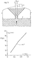
- Versuche mit einem Schaumzerstörer der glatten Form (4 Kanäle, a = 45°; d = 200 mm, d/dR = 10), welcher in einem Behälter von 400 mm Durchmesser knapp unterhalb des Deckels angeordnet war, Fig. 5, und bei denen mit gleichem Stoffsystem wie zuvor gearbeitet wurde, zeigten, dass sich dieser Schaumzerstörer bestens zum Betrieb innerhalb eines Behälters eignet. Fig. 6 zeigt die bei diesen Versuchen ermittelte Abhängigkeit der Mindest-Umfangsgeschwindigkeit umin von der Leerrohrgeschwindigkeit des Schaumes im Ansaugstutzen.
- Die in Fig. 4 aufgezeigte, erfindungsgemäss bevorzugte, glatte Ausführungsform des Schaumzerstörers erfüllt alle Voraussetzungen, die eingangs als Bedingungen für einen leistungsfähigen und wartungsfreien Apparat genannt worden sind. Der Schaumzerstörer kann auch aus verschiedenen Materialien, vorzugsweise Leichtmetall oder auch aus Kunststoff, gefertigt werden und lässt sich bei Bedarf schnell reinigen.
- Vorzugsweise weisen die Kanäle einen runden Querschnitt auf. Die Länge der Kanäle ist erfindungsgemäss durch den gewählten Winkel a und den Durchmesser d begrenzt. Die Austrittsöffnungen der Kanäle liegen alle in einer Ebene innerhalb eines Kreises, dessen Durchmesser mit d angegeben ist. In der Fig. 1 und 4 ist der Radius des Kreises mit d/2 angegeben.
- Die Zahl der Kanäle hat auf die Mindestumfangsgeschwindigkeit einen vergleichsweise geringen Einfluss. Besonders gute Ergebnisse werden erfindungsgemäss erzielt, wenn der Schaumzerstörer mindestens drei, vorzugsweise 4-10 und ganz besonders bevorzugt 4-8 Kanäle enthält.
- Vorzugsweise beträgt der Durchmesser d mindestens 200 mm, besonders bevorzugt über 250 mm.
- Der Innendurchmesser des Ansaugstutzens (d1) in dem Teil, wo die Kanäle abzweigen, sollte mindestens 20 mm betragen. In einer erfindungsgemäss besonders bevorzugten Ausführungsform liegt das Verhältnis von d zu d1 zwischen 2 und 6, vorzugsweise 3 und 4 und das Verhältnis von d zu dR (Kanaldurchmesser) zwischen 6 und 12, vorzugsweise 8 und 10.
- dR ist laut dem Satz zuvor mit d gekoppelt und damit bereits bestimmt.
Claims (7)
Priority Applications (1)
| Application Number | Priority Date | Filing Date | Title |
|---|---|---|---|
| AT81101401T ATE7361T1 (de) | 1980-03-06 | 1981-02-26 | Mechanischer schaumzerstoerer und verfahren zur mechanischen schaumzerstoerung. |
Applications Claiming Priority (2)
| Application Number | Priority Date | Filing Date | Title |
|---|---|---|---|
| DE19803008589 DE3008589A1 (de) | 1980-03-06 | 1980-03-06 | Mechanischer schaumzerstoerer und verfahren zur mechanischen schaumzerstoerung |
| DE3008589 | 1980-03-06 |
Publications (3)
| Publication Number | Publication Date |
|---|---|
| EP0035705A2 EP0035705A2 (de) | 1981-09-16 |
| EP0035705A3 EP0035705A3 (en) | 1982-03-03 |
| EP0035705B1 true EP0035705B1 (de) | 1984-05-09 |
Family
ID=6096441
Family Applications (1)
| Application Number | Title | Priority Date | Filing Date |
|---|---|---|---|
| EP81101401A Expired EP0035705B1 (de) | 1980-03-06 | 1981-02-26 | Mechanischer Schaumzerstörer und Verfahren zur mechanischen Schaumzerstörung |
Country Status (7)
| Country | Link |
|---|---|
| US (1) | US4508546A (de) |
| EP (1) | EP0035705B1 (de) |
| JP (1) | JPS56136608A (de) |
| AT (1) | ATE7361T1 (de) |
| DE (2) | DE3008589A1 (de) |
| ES (1) | ES8201433A1 (de) |
| ZA (1) | ZA811473B (de) |
Cited By (3)
| Publication number | Priority date | Publication date | Assignee | Title |
|---|---|---|---|---|
| DE102015122463A1 (de) | 2015-12-21 | 2017-06-22 | Endress+Hauser Conducta Gmbh+Co. Kg | Membran und Verfahren zum Herstellen einer Membran |
| US9981202B2 (en) | 2013-03-14 | 2018-05-29 | Hans Heidolph GmbH | Rotary evaporator with mechanical foam breaker |
| EP4382184A1 (de) | 2022-12-06 | 2024-06-12 | Yara International ASA | System zum brechen eines flüssigschaums und verfahren zum betrieb davon |
Families Citing this family (13)
| Publication number | Priority date | Publication date | Assignee | Title |
|---|---|---|---|---|
| DE3331993A1 (de) * | 1983-09-05 | 1984-03-29 | Heinz Prof. Dr.-Ing. 7261 Gechingen Blenke | Verfahren und vorrichtung zur entgasung von gas-liquid-systemen ohne schaumbildung |
| PH31227A (en) * | 1994-03-15 | 1998-05-12 | Boc Group Plc | Gas dissolving. |
| DE19711021A1 (de) * | 1997-03-17 | 1998-09-24 | Basf Ag | Verwendung von mechanischen Schaumzerstörern bei der Polymerdispersions-Herstellung |
| JP3675176B2 (ja) * | 1998-06-19 | 2005-07-27 | 株式会社カツシカ | 棒状化粧料繰り出し容器 |
| KR100346521B1 (ko) * | 2000-03-28 | 2002-07-27 | 주식회사 엘지씨아이 | 폼 분리기용 임펠러 |
| WO2007001293A1 (en) * | 2005-06-23 | 2007-01-04 | Hewlett-Packard Development Company, L.P. | System and method for controlling foam in a printing system |
| CN103480184B (zh) * | 2013-10-12 | 2015-08-12 | 象山医疗精密仪器有限公司 | 药液破泡除沫器 |
| EP3420859A1 (de) * | 2017-06-30 | 2019-01-02 | Koninklijke Philips N.V. | Entsaftungsvorrichtung und entsaftungsverfahren |
| CN109797810B (zh) * | 2019-01-17 | 2024-05-07 | 广东省水利水电科学研究院 | 一种应用于高水头供水构筑物的弯管分流消泡装置 |
| WO2022096284A1 (en) * | 2020-11-03 | 2022-05-12 | Global Life Sciences Solutions Usa Llc | Sterile foam breaking system and associated method thereof |
| CN112893009A (zh) * | 2021-01-18 | 2021-06-04 | 南京宝芝泉技术研发有限公司 | 一种具有除泡功能的点胶设备 |
| CN113415846A (zh) * | 2021-08-10 | 2021-09-21 | 西南兵工重庆环境保护研究所有限公司 | 一种简易的物理消泡方法 |
| WO2024019981A1 (en) * | 2022-07-18 | 2024-01-25 | Life Technologies Corporation | Foam breaker device and methods of use |
Family Cites Families (23)
| Publication number | Priority date | Publication date | Assignee | Title |
|---|---|---|---|---|
| US1007266A (en) * | 1910-10-28 | 1911-10-31 | Delavan V Burrell | Centrifugal pump. |
| DE329658C (de) * | 1916-05-01 | 1920-11-30 | Georg A Krause | Verfahren und Vorrichtungen zum Verdampfen oder Eindicken von Loesungen, Emulsionen und Suspensionen, sowie zur Ausfuehrung chemischer Reaktionen |
| US1609413A (en) * | 1925-03-28 | 1926-12-07 | Kristoffersson Magnus | Foam-destroying device |
| US1967938A (en) * | 1931-10-27 | 1934-07-24 | Jantzen Ernst | Foam separator for fermentation plants and the like |
| US2276404A (en) * | 1939-10-10 | 1942-03-17 | Wright Aeronautical Corp | Shrouded impeller |
| US2472412A (en) * | 1947-03-14 | 1949-06-07 | Walter B Fritz | Impeller for centrifugal force pumps |
| US2608474A (en) * | 1949-01-14 | 1952-08-26 | Shell Dev | Apparatus for contacting gaseous fluids with powdered solids |
| US2805889A (en) * | 1954-11-23 | 1957-09-10 | Bendix Aviat Corp | Couple force nozzle |
| US3100027A (en) * | 1960-10-12 | 1963-08-06 | Western Electric Co | One-piece oil pump |
| US3128084A (en) * | 1961-11-15 | 1964-04-07 | Wilbur W Castor | Stirrer |
| US3213592A (en) * | 1963-02-21 | 1965-10-26 | Northern Ind Inc | Liquid treatment |
| US3301490A (en) * | 1964-12-07 | 1967-01-31 | Rain Jet Corp | Multiple outlet water discharge head with internal flow distributing baffle |
| US3256677A (en) * | 1965-02-05 | 1966-06-21 | Mixing Equipment Co Inc | Defoaming |
| CH449585A (de) * | 1967-02-28 | 1968-01-15 | Process Engineering Co | Vorrichtung zur kontinuierlichen Trennung von Schäumen in ihre flüssigen und gasförmigen Komponenten |
| FR1595991A (de) * | 1968-02-23 | 1970-06-15 | ||
| DE1750319A1 (de) * | 1968-04-20 | 1971-02-11 | Dr Heinrich Winter | Verfahren und Vorrichtung zum Zerteilen von Fluessigkeiten,insbesondere von metallischen Schmelzen |
| US3768726A (en) * | 1970-05-06 | 1973-10-30 | Autometrics Co | Method and apparatus for the removal of entrained gases from mineral slurries, pulps, liquids, and the like |
| US3773258A (en) * | 1972-12-11 | 1973-11-20 | Rain Jet Corp | Controllable multitier fountain |
| DE2345374A1 (de) * | 1973-09-06 | 1975-03-20 | Schering Ag | Vorrichtung zur schaumzerstoerung |
| DE2428312A1 (de) * | 1974-06-13 | 1976-01-02 | Schering Ag | Vorrichtung zur schaumzerstoerung |
| US4110089A (en) * | 1974-05-13 | 1978-08-29 | Mueller Hans | Apparatus with foam breaker |
| IL55501A0 (en) * | 1977-09-14 | 1978-12-17 | Bals Edward Julius | Ratary atomiser |
| SU687262A1 (ru) * | 1977-09-22 | 1979-09-25 | Башкирский государственный научно-исследовательский и проектный институт нефтяной промышленности | Рабочее колесо насоса |
-
1980
- 1980-03-06 DE DE19803008589 patent/DE3008589A1/de not_active Withdrawn
-
1981
- 1981-02-23 US US06/236,485 patent/US4508546A/en not_active Expired - Lifetime
- 1981-02-26 EP EP81101401A patent/EP0035705B1/de not_active Expired
- 1981-02-26 DE DE8181101401T patent/DE3163456D1/de not_active Expired
- 1981-02-26 AT AT81101401T patent/ATE7361T1/de not_active IP Right Cessation
- 1981-03-05 JP JP3059181A patent/JPS56136608A/ja active Pending
- 1981-03-05 ES ES500123A patent/ES8201433A1/es not_active Expired
- 1981-03-05 ZA ZA00811473A patent/ZA811473B/xx unknown
Cited By (4)
| Publication number | Priority date | Publication date | Assignee | Title |
|---|---|---|---|---|
| US9981202B2 (en) | 2013-03-14 | 2018-05-29 | Hans Heidolph GmbH | Rotary evaporator with mechanical foam breaker |
| DE102015122463A1 (de) | 2015-12-21 | 2017-06-22 | Endress+Hauser Conducta Gmbh+Co. Kg | Membran und Verfahren zum Herstellen einer Membran |
| EP4382184A1 (de) | 2022-12-06 | 2024-06-12 | Yara International ASA | System zum brechen eines flüssigschaums und verfahren zum betrieb davon |
| WO2024121192A1 (en) | 2022-12-06 | 2024-06-13 | Yara International Asa | System for breaking a liquid foam and method of operating thereof |
Also Published As
| Publication number | Publication date |
|---|---|
| JPS56136608A (en) | 1981-10-26 |
| EP0035705A2 (de) | 1981-09-16 |
| ES500123A0 (es) | 1981-12-16 |
| ZA811473B (en) | 1982-03-31 |
| DE3163456D1 (en) | 1984-06-14 |
| EP0035705A3 (en) | 1982-03-03 |
| ES8201433A1 (es) | 1981-12-16 |
| US4508546A (en) | 1985-04-02 |
| ATE7361T1 (de) | 1984-05-15 |
| DE3008589A1 (de) | 1981-09-10 |
Similar Documents
| Publication | Publication Date | Title |
|---|---|---|
| EP0035705B1 (de) | Mechanischer Schaumzerstörer und Verfahren zur mechanischen Schaumzerstörung | |
| DE2524544A1 (de) | Vorrichtung und verfahren zur behandlung von gasen oder fluessigkeiten, die durch feste teilchen verunreinigt sind | |
| DE3606447A1 (de) | Siebvorrichtung | |
| DE2633126C2 (de) | Vorrichtung zum Beseitigen von Schaum, der auf der Oberfläche einer Flüssigkeit auftritt | |
| EP0134890A2 (de) | Vorrichtung zum Herstellen hochwertiger Feststoff-Flüssigkeits-Gemische bis zum kolloiden System oder bis zur Koagulation, zur Wasseraufbereitung oder zum Einbringen von Gasen in Flüssigkeiten | |
| EP0338198A1 (de) | Absetzbehälter für eine Belebtschlamm-Abwasser-Suspension | |
| EP0220591B1 (de) | Fermentationsanlage | |
| EP0044498A1 (de) | Vorrichtung zum Begasen von Flüssigkeiten oder Suspensionen | |
| DE1909315C3 (de) | Verfahren zum Isolieren von in einem organischen Lösungsmittel gelösten Polymeren oder Copolymeren | |
| DE3032887C2 (de) | ||
| DE102009031103A1 (de) | Verfahren und Vorrichtung zum Entgasen einer Flüssigkeit | |
| EP0430985A1 (de) | Vorrichtung zur aufbereitung flüssiger bis dünnbreiiger medien. | |
| DE3331993C2 (de) | ||
| DE3325952A1 (de) | Vorrichtung zum herstellen hochwertiger feststoff-fluessigkeits-gemische bis zum kolloiden system | |
| DE69003470T2 (de) | Verfahren und Vorrichtung zum Einspritzen flüssiger Stoffe in ein Flotationsbecken. | |
| DE688803C (de) | Vorrichtung zum Ausscheiden von spezifisch schwereren Beimengungen aus Gasen, Daempfen oder Fluessigkeiten | |
| DE4138179C2 (de) | Vorrichtung zur deckschichtfreien Membranfiltration | |
| DE7736318U1 (de) | Vorrichtung zur zerlegung von schaum | |
| DE3428533C2 (de) | ||
| DE202024000402U1 (de) | Einrichtung zur Bekämpfung von Wasser mit Eiern, Larven und/oder Jungmuscheln der Quaggamuschel durch Kavitation mit einem Behälter | |
| DE29506119U1 (de) | Einrichtung zur Herstellung einer mit einem gasförmigen Medium versetzten Flüssigkeit durch Fördern von reinen und/oder durch Schwebestoffe belasteten Flüssigkeiten mit einer anschließenden Zerstäubung derselben | |
| DE1221241B (de) | Vorrichtung zum Trennen von feuchtem Dampf | |
| DE3620999A1 (de) | Vorrichtung zur entfernung von blasen | |
| DE102024000688A1 (de) | Einrichtung zur Bekämpfung von Wasser mit Eiern, Larven und/oder Jungmuscheln der Quaggamuschel durch Kavitation mit einem Behälter | |
| CH616857A5 (en) | Method and apparatus for continuous foam dispersion |
Legal Events
| Date | Code | Title | Description |
|---|---|---|---|
| PUAI | Public reference made under article 153(3) epc to a published international application that has entered the european phase |
Free format text: ORIGINAL CODE: 0009012 |
|
| AK | Designated contracting states |
Designated state(s): AT BE CH DE FR GB NL |
|
| PUAL | Search report despatched |
Free format text: ORIGINAL CODE: 0009013 |
|
| AK | Designated contracting states |
Designated state(s): AT BE CH DE FR GB NL |
|
| 17P | Request for examination filed |
Effective date: 19810306 |
|
| GRAA | (expected) grant |
Free format text: ORIGINAL CODE: 0009210 |
|
| AK | Designated contracting states |
Designated state(s): AT BE CH DE FR GB LI NL |
|
| REF | Corresponds to: |
Ref document number: 7361 Country of ref document: AT Date of ref document: 19840515 Kind code of ref document: T |
|
| REF | Corresponds to: |
Ref document number: 3163456 Country of ref document: DE Date of ref document: 19840614 |
|
| ET | Fr: translation filed | ||
| PLBE | No opposition filed within time limit |
Free format text: ORIGINAL CODE: 0009261 |
|
| STAA | Information on the status of an ep patent application or granted ep patent |
Free format text: STATUS: NO OPPOSITION FILED WITHIN TIME LIMIT |
|
| 26N | No opposition filed | ||
| PGFP | Annual fee paid to national office [announced via postgrant information from national office to epo] |
Ref country code: DE Payment date: 19980115 Year of fee payment: 18 |
|
| PGFP | Annual fee paid to national office [announced via postgrant information from national office to epo] |
Ref country code: FR Payment date: 19980126 Year of fee payment: 18 |
|
| PGFP | Annual fee paid to national office [announced via postgrant information from national office to epo] |
Ref country code: GB Payment date: 19980217 Year of fee payment: 18 |
|
| PGFP | Annual fee paid to national office [announced via postgrant information from national office to epo] |
Ref country code: AT Payment date: 19980219 Year of fee payment: 18 |
|
| PGFP | Annual fee paid to national office [announced via postgrant information from national office to epo] |
Ref country code: BE Payment date: 19980225 Year of fee payment: 18 |
|
| PGFP | Annual fee paid to national office [announced via postgrant information from national office to epo] |
Ref country code: NL Payment date: 19980228 Year of fee payment: 18 |
|
| PGFP | Annual fee paid to national office [announced via postgrant information from national office to epo] |
Ref country code: CH Payment date: 19980302 Year of fee payment: 18 |
|
| PG25 | Lapsed in a contracting state [announced via postgrant information from national office to epo] |
Ref country code: GB Free format text: LAPSE BECAUSE OF NON-PAYMENT OF DUE FEES Effective date: 19990226 Ref country code: AT Free format text: LAPSE BECAUSE OF NON-PAYMENT OF DUE FEES Effective date: 19990226 |
|
| PG25 | Lapsed in a contracting state [announced via postgrant information from national office to epo] |
Ref country code: LI Free format text: LAPSE BECAUSE OF NON-PAYMENT OF DUE FEES Effective date: 19990228 Ref country code: CH Free format text: LAPSE BECAUSE OF NON-PAYMENT OF DUE FEES Effective date: 19990228 Ref country code: BE Free format text: LAPSE BECAUSE OF NON-PAYMENT OF DUE FEES Effective date: 19990228 |
|
| BERE | Be: lapsed |
Owner name: BAYER A.G. Effective date: 19990228 |
|
| PG25 | Lapsed in a contracting state [announced via postgrant information from national office to epo] |
Ref country code: NL Free format text: LAPSE BECAUSE OF NON-PAYMENT OF DUE FEES Effective date: 19990901 |
|
| GBPC | Gb: european patent ceased through non-payment of renewal fee |
Effective date: 19990226 |
|
| REG | Reference to a national code |
Ref country code: CH Ref legal event code: PL |
|
| PG25 | Lapsed in a contracting state [announced via postgrant information from national office to epo] |
Ref country code: FR Free format text: LAPSE BECAUSE OF NON-PAYMENT OF DUE FEES Effective date: 19991029 |
|
| PG25 | Lapsed in a contracting state [announced via postgrant information from national office to epo] |
Ref country code: DE Free format text: LAPSE BECAUSE OF NON-PAYMENT OF DUE FEES Effective date: 19991201 |
|
| REG | Reference to a national code |
Ref country code: FR Ref legal event code: ST |