EP0035455A1 - Dispositif de suspension et de liaison entre un châssis de bogie et une boîte d'essieu - Google Patents
Dispositif de suspension et de liaison entre un châssis de bogie et une boîte d'essieu Download PDFInfo
- Publication number
- EP0035455A1 EP0035455A1 EP81400329A EP81400329A EP0035455A1 EP 0035455 A1 EP0035455 A1 EP 0035455A1 EP 81400329 A EP81400329 A EP 81400329A EP 81400329 A EP81400329 A EP 81400329A EP 0035455 A1 EP0035455 A1 EP 0035455A1
- Authority
- EP
- European Patent Office
- Prior art keywords
- axle
- axle box
- elastic
- axis
- vertical
- Prior art date
- Legal status (The legal status is an assumption and is not a legal conclusion. Google has not performed a legal analysis and makes no representation as to the accuracy of the status listed.)
- Withdrawn
Links
- 239000000725 suspension Substances 0.000 title claims abstract description 23
- 239000002184 metal Substances 0.000 claims abstract description 8
- 229920001971 elastomer Polymers 0.000 claims description 9
- 239000000806 elastomer Substances 0.000 claims description 8
- 239000000463 material Substances 0.000 claims description 4
- 239000013536 elastomeric material Substances 0.000 abstract description 7
- 230000006835 compression Effects 0.000 description 4
- 238000007906 compression Methods 0.000 description 4
- 238000009432 framing Methods 0.000 description 2
- 238000000926 separation method Methods 0.000 description 2
- 229910000831 Steel Inorganic materials 0.000 description 1
- 239000000470 constituent Substances 0.000 description 1
- 230000007423 decrease Effects 0.000 description 1
- 238000009434 installation Methods 0.000 description 1
- 239000010959 steel Substances 0.000 description 1
Images
Classifications
-
- B—PERFORMING OPERATIONS; TRANSPORTING
- B61—RAILWAYS
- B61F—RAIL VEHICLE SUSPENSIONS, e.g. UNDERFRAMES, BOGIES OR ARRANGEMENTS OF WHEEL AXLES; RAIL VEHICLES FOR USE ON TRACKS OF DIFFERENT WIDTH; PREVENTING DERAILING OF RAIL VEHICLES; WHEEL GUARDS, OBSTRUCTION REMOVERS OR THE LIKE FOR RAIL VEHICLES
- B61F5/00—Constructional details of bogies; Connections between bogies and vehicle underframes; Arrangements or devices for adjusting or allowing self-adjustment of wheel axles or bogies when rounding curves
- B61F5/26—Mounting or securing axle-boxes in vehicle or bogie underframes
- B61F5/30—Axle-boxes mounted for movement under spring control in vehicle or bogie underframes
Definitions
- the present invention relates to a suspension and connection device between the bogre chassis and each axle box fitted to an axle of a motor or carrier rail bogie undercarriage.
- each axle box In a bogie suspension, elasticity must be provided in the vertical direction between the bogie chassis and each axle box. It is also necessary that each axle box is guided 'relative to the chassis, longitudinally and transversely.
- bogie chassis Various types of bogie are known in which elastomeric studs are mounted between the bogie chassis and each axle box.
- Each elastic pad is housed between two parallel bearing faces and slightly inclined relative to the vertical.
- the studs are arranged, two by two, in dihedrons such that the bisector planes are vertical, this arrangement in dihedrons making it possible to support a vertical load under combined stress of compression and shear.
- the rigidity following the vertical direction is not negligible.
- each elastomer block is housed between two parallel bearing faces and slightly inclined relative to the vertical.
- These elastic studs are arranged, two by two, in dihedrons whose bisecting planes are vertical so that the vertical loads are supported under combined compressive and shear stresses.
- the elastomer pads are mounted in parallel with the vertical suspension springs. This arrangement disturbs the operation, in particular at high frequency stresses.
- the suspension and the connection between the bogie chassis and the axle box include a helical spring and elastic studs framing the axle box.
- Each elastic pad is housed between two vertical bearing faces.
- the elastomeric material is prestressed by crushing. Under the effect of creep, the prestress decreases over time.
- the present invention relates to a device ensuring the vertical suspension of the bogie chassis and the longitudinal and transverse connection of each axle box and the chassis and capable of providing, without disturbing the vertical suspension, a certain radial and axial elasticity of the 'axle.
- This device uses pads made of elastomeric material, prestressed so that the prestress does not change over time. Therefore the guiding characteristics are constant and independent of the creep of the material and the vertical dynamics of the suspension is not changed.
- the device according to the invention comprises at least one helical metal spring for vertical suspension by which the bogie frame rests on the axle box and on the other hand elastic connections each comprising at least one stud, made of elastomeric material, clamped between bearing faces of said chassis and of said axle box and it is essentially characterized in that the elastic connections are monoblock and are mounted apart at altitude and so that they are compressed under the effect of a torque given by the vertical suspension spring.
- connections are arranged on either side of the vertical plane passing through the axle axis.
- the elastic connections are arranged on either side of the horizontal plane passing through the axle axis.
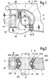
- Figure 1 is an elevational view of the suspension and connection device mounted between the bogie chassis and an axle box.
- FIG. 2 represents a section along A.A of FIG. 1.
- the bogie shown in FIGS. 1 and 2 comprises a bogie chassis 2 which is suspended on a running gear comprising axles 1. Each axle is equipped with two axle boxes3.
- each axle box is provided by at least one steel coil spring 4.
- Each coil spring is mounted vertically between the bogie chassis and the axle box. The positioning of the spring or springs, relative to the vertical plane 8 passing through the axle axis, is such that the body of the axle box is subjected to a force or load F, offset laterally relative to this plane 8, and is therefore subject to a torque.
- a single helical spring 4 is placed at a well-determined distance from the vertical plane 8, on one side of the axle box.
- This spring is housed so as to be compressed between a horizontal upper surface 21 of the chassis and a horizontal lower surface 31 formed on the console 32 of the axle box.
- the vertical axis 41 of the spring 4 is located laterally at a finite distance L from the vertical plane 8 passing through the axis 11 of the axle 1.
- the axle box is linked to the bogie chassis by elastic connections 5 and 6 which are each preferably made up of two elastic studs.
- One of the connections 5 is constituted by two elastic studs 51-52, the other elastic connection6 being constituted by two elastic studs 61-62.
- the elastic connection 5 and the elastic connection 6 are mounted apart at altitude to balance the torque applied to the axle box.
- the upper elastic connection 5 formed by the elastic studs 51 and 52 is located on the side of the spring 4 relative to the vertical plane passing through the axis 11 of the axle. It is located above the horizontal plane 7 passing through the axis 11 of revolution of the axle, between the load transmitted by the helical spring (s) and the vertical plane 8 passing through this axis 11 or between this vertical plane and the parallel plane passing through the axis 41 of the spring.
- the lower elastic connection 6 constituted by the elastic studs 61 and 62 is situated, with respect to the spring 4 and to the upper connection, on the other side of the vertical plane 8 passing through the axis 11.
- the connection 5 and the connection 6 are mounted on either side of the vertical plane 8.
- connection 6 is located below the horizontal plane 7 passing through the axis of revolution 11 of the axle, beyond, relative to the spring, the vertical plane 8 passing through this axis 11.
- the elastic connection 5 formed by the upper elastic studs 51 and 52 and the elastic connection 6 formed by the lower elastic studs 61 and 62 are located on either side of the vertical plane 8 passing through the axis of bygone tion of the axle.
- the distance between the center of an upper elastic stud 51 or 52 and the axis of revolution of the axle is substantially equal to the distance between the center of a lower elastic stud 61 or 62 and this same axis of revolution.
- the upper elastic link 5 and the lower elastic link 6 are mounted symmetrically with respect to the axis of revolution of the axle.
- Each elastic stud has a prismatic or cylindrical shape whose terminal straight sections are parallel and immobilized respectively against a bearing face of the axle box and a bearing face of the bogie chassis.
- the studs 51 and 52 are respectively enclosed between bearing faces 351 and 352 of the axle box which face the vertical spring and opposite bearing faces 251 and 252 which are formed on the bogie frame.
- the lower studs 61 and 62 are sandwiched respectively between bearing faces 361 and 362 of the axle box which are turned on the side opposite to the vertical spring and opposite bearing faces 261 and 262, formed on the bogie chassis. .
- the two bearing faces of each elastic pad are substantially vertical.
- the bearing faces of the axle box 351-352 and 361-362 are in opposition.
- the upper bearing faces 351-352 of the box relative to the upper elastic connection are oriented on the side of the load F, transmitted by the metal spring or springs.
- the bearing faces 351-352 are turned towards the spring 4.
- These bearing faces face the result of the forces transmitted by the springs in the case where several springs are fitted between the chassis.de.bogie and the axle box.
- the lower bearing faces 361-362 are turned on the opposite side. This arrangement causes the compression of the elastic pads. In all cases the bearing faces on the axle box are always oriented in the same way with respect to the torque generated by the forces on the springs.
- Each elastic stud 51 or 52 constitutes a single piece capable of supporting, without the possibility of separation, sliding or friction of its constituent parts, a tensile, compression or shear force or a combined force applied between its terminal sections which are fixed without possibility of separation or sliding respectively to a bearing face of the axle box and to a bearing face of the bogie chassis.
- the terminal sections - preferably flat - are made up by rigid metal plates adhered to the elastomer or rubber material and immobilized respectively against the bearing faces of the axle box and of the bogie chassis.
- Each elastic pad comprises, between the metal end plates, an elastomeric material. It can be constituted by a sandwitch or laminated structure produced by elastomer plates and metal plates arranged alternately, the plates of elastomer material being adhered to the intermediate metal plates.
- the bearing faces of the elastomer pads on the axle box and the bogie chassis can be arranged according to one of the various arrangements currently known, depending on the performance required for guiding the axle box and in depending on the type of bogie.
- the faces of bearing supports either against the axle box or against the bogie chassis can be flat.
- the bearing faces of the various elastic studs can still be applied according to cylindrical surfaces of the axle box or of the bogie chassis.
- the bearing faces of each elastic connection can also be arranged in dihedrons, two elastic studs being mounted between the dihedrons.
- the two bearing faces 261 and 262 on the chassis of the two lower elastic studs and the two opposite bearing faces 361 and 362 on the axle box form dihedrons having a common bisector plane perpendicular to the axis of axle revolution.
- the elastic studs 51 and 52 are mounted "chevron", symmetrically with respect to the vertical plane passing through the axis 41 and perpendicular to the axis of revolution of the axle.
- the lower elastic studs 61 and 62 are also mounted in a "chevron”, symmetrically with respect to the plane defined above.
- the elastic studs are identical from the point of view of the dimensions and from the point of view of the constitution.
- the vertical suspension spring and the upper elastic studs 51 and 52 are mounted towards the outside of the bogie relative to the vertical plane 8 passing through the axis of revolution of the axle.
- the lower elastic studs 61 and 62 are mounted towards the center of the bogie relative to this same vertical plane 8.
- the vertical suspension spring 4 can be composed of a single spring / of several springs mounted coaxially.
- the vertical suspension spring (s) exert a force F (resulting in the case of several springs) on the axle box 3. Because the load F is applied to the axle box at a non-zero distance from the plane vertical 8 passing through the axis of revolution 11 of the axle, this force F creates a torque which tends to pivot the axle box around this axis 11, by compressing the elastic pads 51, 52, 61, 62 Each elastic pad is subjected to a compression force P defined by the ratio L / l of the lever arms and the load F supported by the vertical spring. This force is constant and independent of the creep of the elastomeric material constituting the elastic pads.
- the mechanical properties of the elastomeric material are such that the compressive force applied results in a shear stiffness of the studs, in the vertical direction, low or zero.
- the studs deform during the relative vertical deflections of the axle box and the chassis without the total instability of the elastic studs.
- the elastic pads provide, with a certain flexibility, the longitudinal drive of the axle.
- the elastic studs ensure, with a certain flexibility, the lateral or transverse guidance of the axle.
- the helical spring 4 is mounted offset from the axis of the axle, it can be placed either outside or inside the bogie. When it is placed outside, the lower elastic pads are located towards the center of the bogie and installation under lowered vehicles is facilitated.
Landscapes
- Engineering & Computer Science (AREA)
- Mechanical Engineering (AREA)
- Vibration Prevention Devices (AREA)
- Springs (AREA)
Applications Claiming Priority (2)
| Application Number | Priority Date | Filing Date | Title |
|---|---|---|---|
| FR8004782 | 1980-03-04 | ||
| FR8004782A FR2477489A1 (fr) | 1980-03-04 | 1980-03-04 | Dispositif de suspension et de liaison entre un chassis de bogie et une boite d'essieu |
Publications (1)
| Publication Number | Publication Date |
|---|---|
| EP0035455A1 true EP0035455A1 (fr) | 1981-09-09 |
Family
ID=9239277
Family Applications (1)
| Application Number | Title | Priority Date | Filing Date |
|---|---|---|---|
| EP81400329A Withdrawn EP0035455A1 (fr) | 1980-03-04 | 1981-03-04 | Dispositif de suspension et de liaison entre un châssis de bogie et une boîte d'essieu |
Country Status (11)
| Country | Link |
|---|---|
| EP (1) | EP0035455A1 (Direct) |
| JP (1) | JPS56138058A (Direct) |
| AU (1) | AU6762081A (Direct) |
| BE (1) | BE887747A (Direct) |
| BR (1) | BR8101110A (Direct) |
| CA (1) | CA1170912A (Direct) |
| CH (1) | CH642016A5 (Direct) |
| FR (1) | FR2477489A1 (Direct) |
| IT (1) | IT8167296A0 (Direct) |
| LU (1) | LU83184A1 (Direct) |
| ZA (1) | ZA811218B (Direct) |
Cited By (4)
| Publication number | Priority date | Publication date | Assignee | Title |
|---|---|---|---|---|
| WO1982004423A1 (fr) * | 1981-06-19 | 1982-12-23 | Pinto Georges | Dispositif de suspension et de liaison entre un chassis de bogie et un boite d'essieu |
| FR2550504A1 (fr) * | 1983-08-12 | 1985-02-15 | Budd Co | Suspension primaire de vehicule ferroviaire |
| FR2583364A1 (fr) * | 1985-06-14 | 1986-12-19 | Schneider Jeumont Rail | Suspension pour bogie de vehicule ferroviaire |
| FR2723902A1 (fr) * | 1994-08-26 | 1996-03-01 | Niesky Waggonbau Gmbh | Train de roulement pour des vehicules ferroviaires |
Families Citing this family (1)
| Publication number | Priority date | Publication date | Assignee | Title |
|---|---|---|---|---|
| US4433629A (en) | 1981-12-09 | 1984-02-28 | General Motors Corporation | Railway truck bearing mounting assembly |
Citations (5)
| Publication number | Priority date | Publication date | Assignee | Title |
|---|---|---|---|---|
| US2836130A (en) * | 1956-11-13 | 1958-05-27 | Transit Res Corp | Journal bearing assembly |
| FR1490064A (fr) * | 1965-08-26 | 1967-07-28 | Linke Hofmann Busch | Suspension pour véhicules à un ou plusieurs essieux, et plus particulièrement pour des véhicules ferroviaires |
| AT323230B (de) * | 1973-12-13 | 1975-06-25 | Held Otto Ing | Zweiachsiges drehgestell für schienenfahrzeuge |
| DE2404518A1 (de) * | 1974-01-31 | 1975-08-07 | Clouth Gummiwerke Ag | Elastische lagerung fuer die achslager der drehgestelle von schienenfahrzeugen |
| FR2317145A1 (fr) * | 1975-07-07 | 1977-02-04 | Gloucester Railway Carriage | Vehicule ferroviaire |
-
1980
- 1980-03-04 FR FR8004782A patent/FR2477489A1/fr active Granted
-
1981
- 1981-02-24 CH CH122581A patent/CH642016A5/fr not_active IP Right Cessation
- 1981-02-24 ZA ZA00811218A patent/ZA811218B/xx unknown
- 1981-02-24 BR BR8101110A patent/BR8101110A/pt unknown
- 1981-02-25 AU AU67620/81A patent/AU6762081A/en not_active Abandoned
- 1981-03-02 JP JP2977981A patent/JPS56138058A/ja active Pending
- 1981-03-02 BE BE0/203975A patent/BE887747A/fr not_active IP Right Cessation
- 1981-03-03 CA CA000372199A patent/CA1170912A/fr not_active Expired
- 1981-03-03 IT IT8167296A patent/IT8167296A0/it unknown
- 1981-03-03 LU LU83184A patent/LU83184A1/fr unknown
- 1981-03-04 EP EP81400329A patent/EP0035455A1/fr not_active Withdrawn
Patent Citations (5)
| Publication number | Priority date | Publication date | Assignee | Title |
|---|---|---|---|---|
| US2836130A (en) * | 1956-11-13 | 1958-05-27 | Transit Res Corp | Journal bearing assembly |
| FR1490064A (fr) * | 1965-08-26 | 1967-07-28 | Linke Hofmann Busch | Suspension pour véhicules à un ou plusieurs essieux, et plus particulièrement pour des véhicules ferroviaires |
| AT323230B (de) * | 1973-12-13 | 1975-06-25 | Held Otto Ing | Zweiachsiges drehgestell für schienenfahrzeuge |
| DE2404518A1 (de) * | 1974-01-31 | 1975-08-07 | Clouth Gummiwerke Ag | Elastische lagerung fuer die achslager der drehgestelle von schienenfahrzeugen |
| FR2317145A1 (fr) * | 1975-07-07 | 1977-02-04 | Gloucester Railway Carriage | Vehicule ferroviaire |
Cited By (6)
| Publication number | Priority date | Publication date | Assignee | Title |
|---|---|---|---|---|
| WO1982004423A1 (fr) * | 1981-06-19 | 1982-12-23 | Pinto Georges | Dispositif de suspension et de liaison entre un chassis de bogie et un boite d'essieu |
| FR2507987A1 (fr) * | 1981-06-19 | 1982-12-24 | Creusot Loire | Dispositif de suspension et de liaison entre un chassis de bogie et une boite d'essieu |
| FR2550504A1 (fr) * | 1983-08-12 | 1985-02-15 | Budd Co | Suspension primaire de vehicule ferroviaire |
| GB2144693A (en) * | 1983-08-12 | 1985-03-13 | Budd Co | Primary suspension system for a railway car |
| FR2583364A1 (fr) * | 1985-06-14 | 1986-12-19 | Schneider Jeumont Rail | Suspension pour bogie de vehicule ferroviaire |
| FR2723902A1 (fr) * | 1994-08-26 | 1996-03-01 | Niesky Waggonbau Gmbh | Train de roulement pour des vehicules ferroviaires |
Also Published As
| Publication number | Publication date |
|---|---|
| JPS56138058A (en) | 1981-10-28 |
| CA1170912A (fr) | 1984-07-17 |
| LU83184A1 (fr) | 1981-06-24 |
| IT8167296A0 (it) | 1981-03-03 |
| FR2477489B1 (Direct) | 1983-09-23 |
| CH642016A5 (fr) | 1984-03-30 |
| FR2477489A1 (fr) | 1981-09-11 |
| AU6762081A (en) | 1981-09-10 |
| ZA811218B (en) | 1982-03-31 |
| BR8101110A (pt) | 1981-09-08 |
| BE887747A (fr) | 1981-09-02 |
Similar Documents
| Publication | Publication Date | Title |
|---|---|---|
| EP0082158B1 (fr) | Dispositif de suspension et de liaison entre un chassis de bogie et une boite d'essieu | |
| CA2279736C (fr) | Bogie a longerons composites | |
| EP2676859B1 (fr) | Bogie de véhicule ferroviaire à suspensions perfectionnées, notamment pour un tramway à plancher bas | |
| EP1199483B1 (fr) | Rotule de liaison, par exemple pour barre anti-roulis de véhicule roulant. | |
| FR2518948A1 (fr) | Suspension primaire souple pour vehicule ferroviaire | |
| EP3650304B1 (fr) | Bogie pour véhicule ferroviaire | |
| CA2487047C (fr) | Dispositif de liaison souple entre un longeron flexible et une boite d'essieu | |
| FR2914610A1 (fr) | Dispositif de suspension primaire d'un bogie de vehicule ferroviaire | |
| FR2511961A1 (fr) | Suspension primaire pour vehicule ferroviaire | |
| EP3222485B1 (fr) | Bogie de vehicule ferroviaire comprenant un dispositif de suspension primaire decale | |
| EP0035455A1 (fr) | Dispositif de suspension et de liaison entre un châssis de bogie et une boîte d'essieu | |
| EP0183619A1 (fr) | Bogie porteur de véhicule ferroviaire | |
| CH671739A5 (Direct) | ||
| EP3222486A1 (fr) | Bogie de véhicule ferroviaire comprenant un châssis abaissé | |
| EP3854655B1 (fr) | Bogie pour véhicule à roues indépendantes et véhicule associé | |
| FR2490172A1 (fr) | Agencement de suspension pour vehicules ferroviaires | |
| EP0277059A1 (fr) | Véhicule ferroviaire à charge répartie sur les quatre essieux orientables par rapport à la caisse | |
| EP4074572B1 (fr) | Bogie moteur de véhicule ferroviaire | |
| EP0048659A1 (fr) | Véhicule terrestre à coque suspendue | |
| CA1151951A (fr) | Bogie double conducteur | |
| EP2394881A1 (fr) | Sommier basculant et suspension secondaire le comportant | |
| BE827597A (fr) | Dispositif de suspension de materiel roulant | |
| FR2761311A1 (fr) | Dispositif de suspension pour siege de vehicule | |
| EP0109910A2 (fr) | Bogie ferroviaire | |
| FR2491849A1 (fr) | Bogie monomoteur de vehicule ferroviaire articule |
Legal Events
| Date | Code | Title | Description |
|---|---|---|---|
| PUAI | Public reference made under article 153(3) epc to a published international application that has entered the european phase |
Free format text: ORIGINAL CODE: 0009012 |
|
| AK | Designated contracting states |
Designated state(s): AT DE FR GB NL SE |
|
| 17P | Request for examination filed |
Effective date: 19810729 |
|
| STAA | Information on the status of an ep patent application or granted ep patent |
Free format text: STATUS: THE APPLICATION IS DEEMED TO BE WITHDRAWN |
|
| 18D | Application deemed to be withdrawn |
Effective date: 19841124 |
|
| RIN1 | Information on inventor provided before grant (corrected) |
Inventor name: PINTO, GEORGES |