EP0034575A2 - Druckknopf-Mechanismus mit Sperrvorrichtung für zwei stabile Stellungen - Google Patents
Druckknopf-Mechanismus mit Sperrvorrichtung für zwei stabile Stellungen Download PDFInfo
- Publication number
- EP0034575A2 EP0034575A2 EP81850018A EP81850018A EP0034575A2 EP 0034575 A2 EP0034575 A2 EP 0034575A2 EP 81850018 A EP81850018 A EP 81850018A EP 81850018 A EP81850018 A EP 81850018A EP 0034575 A2 EP0034575 A2 EP 0034575A2
- Authority
- EP
- European Patent Office
- Prior art keywords
- button
- push
- plate
- stop
- groove
- Prior art date
- Legal status (The legal status is an assumption and is not a legal conclusion. Google has not performed a legal analysis and makes no representation as to the accuracy of the status listed.)
- Granted
Links
Images

Classifications
-
- H—ELECTRICITY
- H01—ELECTRIC ELEMENTS
- H01H—ELECTRIC SWITCHES; RELAYS; SELECTORS; EMERGENCY PROTECTIVE DEVICES
- H01H13/00—Switches having rectilinearly-movable operating part or parts adapted for pushing or pulling in one direction only, e.g. push-button switch
- H01H13/50—Switches having rectilinearly-movable operating part or parts adapted for pushing or pulling in one direction only, e.g. push-button switch having a single operating member
- H01H13/56—Switches having rectilinearly-movable operating part or parts adapted for pushing or pulling in one direction only, e.g. push-button switch having a single operating member the contact returning to its original state upon the next application of operating force
- H01H13/562—Switches having rectilinearly-movable operating part or parts adapted for pushing or pulling in one direction only, e.g. push-button switch having a single operating member the contact returning to its original state upon the next application of operating force making use of a heart shaped cam
Definitions
- the invention relates to a push-button mechanism according to the introduction of claim 1 with a locking device of the type that from a first stable position (the initial position) when depressed, Locks the button to a second stable position and when depressed a second time, returns to the first position.
- a locking device of the type that from a first stable position (the initial position) when depressed, Locks the button to a second stable position and when depressed a second time, returns to the first position.
- Such Locking function of the push-button is, for example, used in telephone instruments for connecting an extra telephone function such as a loudspeaking receiving function or the like.
- British patent No 877,223 describes a push-button mechanism in a ball pen in the handle of which the push-button part is formed as a sleeve whose inner cylindrical surface at the lower part is formed as a heart-shaped cam groove for cooperation with a movable baLL Located in the groove.
- the ball Upon the first depression, the ball runs along an arcuate groove of the heart-shaped cam and assumes a certain position, the sleeve being locked in the depressed position by spring action.
- the ball Upon a second depression of the sleeve, the ball runs along another groove of .the heart-shaped cam groove and the sleeve and the ball return to the original position.
- a common feature of the above mentioned push-button mechanisms is that the heart-shaped cam groove is provided on parts of the mechanism which are either integral with the push-button or with another part that performs another function quite different from that of Locking the push-button in the two bistable positions.
- the ⁇ push-button mechanism according to the present invention employs, Like the known mechanism, a heart-shaped cam and a Locking slot or groove with a ball to obtain the bistable action upon repeated depression of the push-button, but by contrast to the known arrangements, the element in which the heart-shaped cam is constructed is movably arranged in relation to the other elements in the mechanism.
- the button and mounted heart-shaped cam constitute an independent unit which is Locked by the ball, keeping the heart-shaped cam and the button together which, after that, are mounted in the mechanism.
- the object of the present invention is thus to provide a push-button mechanism, for example, for use in the push-button set of a telephone instrument having a bistable action of the mechanism upon two successive depressions of the push-button and in which the Locking element is movably arranged in relation to the other elements.
- the invention is then characterized as it appears from the characterizing partof'claim 1.
- Figure 1 shows a push-button with a cover as seen from the side with a mounted locking device according to the invention.
- Figure 2 shows the button and a washer or plate with a heart-shaped cam included in the Locking device according to the invention.
- Figure 3 shows the button alone according to Figure 2 as seen from beLow.
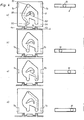
- the Figures 4a-d show the plate according to the Figures 1-2 with heart-shaped cam and belonging ball to illustrate the different phases upon depression.
- the button included in a push-button mechanism for example, a telephone instrument
- a rectangular frame 2 surrounds the button 1 and forms a guide therefore.
- the frame 2 forms an integral part of the cover 3 of the push-button mechanism, the lower part (the base part) of the cover being provided with fastening eLements in the form of two-(or more) supporting Lugs 5a, b.
- the lugs 5a, b are inserted into the holes of a printed card and attached in a suitable manner.
- a Leaf-shaped metal tongue 6 constitutes an electric connection and forms a contact element inside the cover 3 in a known way (not shown in the Figures).
- the cover 3 is in Figure 1 shown cut away to illustrate the position of a thin plate 9 which rests against a rigid support 4 inside the cover (the base part of the cover).
- the part 4 is provided with two protrusions 4a, b between which two Lugs 9a, b of the plate 9 are fitted.
- the button 1 is at its lower end provided with supporting elements for the plate 9 in the form of grip arms 7a, b, which partly fit over the plate 9.
- the arms 7a, 7b at the same time constitute guide elements for the push-button 1 when this is depressed.
- an even groove 8 is formed on the same part as these elements, which groove extends horizontaLLy and in which a smaLL ball 10 is Located.
- the diameter of the ball 10 is suitably chosen somewhat Larger than the depth of the groove 8.
- the ball 10 contacts both the side edges and the LongitudinaL base surface of the groove 8.
- the plate 9 is provided with a countersunk region 11 along one of the plane main surfaces thereof, the outline of which describes a heart-shaped cam according to the dotted Lines in the Figures 1 and 2.
- the plate 9 is inserted between the supporting arms 7a, b so that the countersunk region 11 faces the groove 8.
- a hollow rod 12 is provided inside the button 1, which rod constitutes an integral part with the two arms 7a, b through a connecting part 14.
- a spring 13 is Located in the inner cylindrical cavity of the rod 12 . This rests with its one end on the inside of the button (the base of the rod) and with the other end on the support 4 in the cover 3 so that a spring action is obtained when the button 1 is depressed.
- the Locking device includes the plate 9 with the countersunk region 11, formed as a heart-shaped cam, and the ball 10 Located in the groove 8.
- the plate 9 additionally has a raised portion 15 in the centre of the countersunk region 11, whose upper plane surface is situated LeveL with the upper surface of the plate.
- the plate 9 is inserted between the supporting.arms 7a, b when mounted and the ball 10 snaps into the upper part of the countersunk region 11, i e the tip of the heart-shaped cam, the plate then assuming the position shown in Figure 1.
- the ball 10 is freely movable within the space bounded by the edges of the countersunk region 11 and the edges of the groove 8.
- the button 11 and the heart-shaped cam 9 are now mechanically connected by means of the ball 10 and act as a bistable unit.
- Figure 4a shows the starting position, the first stable position, when the ball 10 is Located at the upper point 111 of the heart-shaped cam.
- the push-button 1 is then in the upper position.
- the button 1 is depressed, the upper edge surface of the groove 8 pushes the ball downwards as shown by the dotted arrow in Figure 4a and the ball passes the convex edge surface 151 of the raised portion 15 and the arcuate edge surface 112 of the heart-shaped cam.
- the ball is in the position shown in Figure 4b when the button is entirely depressed, je in contact with the semicircular edge surface 113.
- the plate 9 with the countersunk region 11 in the form of a heart-shaped cam and the elevated portion 15 in the form of a concave-convex curve is thus flexibly mounted inside the body 3 of the push-button mechanism, and is in principle limited only by the two protrusions 4a, 4b and the supporting arms 7a, 7b.
- the heart-shaped cam which forms one part of the locking mechanism is thus not rigidly mounted in a certain fixed position in relation to the ball 10 when this is running in the groove 8, the second part of the locking arrangement.
- the push-button is freely mounted in known way making that the locking device in the present push-button mechanism complies with the advantages mentioned above.
Landscapes
- Push-Button Switches (AREA)
- Measuring Fluid Pressure (AREA)
- Lock And Its Accessories (AREA)
- Telephone Set Structure (AREA)
- Switches Operated By Changes In Physical Conditions (AREA)
- Arrangement Or Mounting Of Control Devices For Change-Speed Gearing (AREA)
- Switches With Compound Operations (AREA)
Priority Applications (1)
| Application Number | Priority Date | Filing Date | Title |
|---|---|---|---|
| AT81850018T ATE9519T1 (de) | 1980-02-15 | 1981-02-03 | Druckknopf-mechanismus mit sperrvorrichtung fuer zwei stabile stellungen. |
Applications Claiming Priority (2)
| Application Number | Priority Date | Filing Date | Title |
|---|---|---|---|
| SE8001211A SE427225B (sv) | 1980-02-15 | 1980-02-15 | Tryckknappsmekanism |
| SE8001211 | 1980-02-15 |
Publications (3)
| Publication Number | Publication Date |
|---|---|
| EP0034575A2 true EP0034575A2 (de) | 1981-08-26 |
| EP0034575A3 EP0034575A3 (en) | 1982-04-14 |
| EP0034575B1 EP0034575B1 (de) | 1984-09-19 |
Family
ID=20340266
Family Applications (1)
| Application Number | Title | Priority Date | Filing Date |
|---|---|---|---|
| EP81850018A Expired EP0034575B1 (de) | 1980-02-15 | 1981-02-03 | Druckknopf-Mechanismus mit Sperrvorrichtung für zwei stabile Stellungen |
Country Status (8)
| Country | Link |
|---|---|
| US (1) | US4367383A (de) |
| EP (1) | EP0034575B1 (de) |
| AT (1) | ATE9519T1 (de) |
| CA (1) | CA1153407A (de) |
| DE (1) | DE3166100D1 (de) |
| ES (1) | ES267100Y (de) |
| NO (1) | NO154289C (de) |
| SE (1) | SE427225B (de) |
Cited By (3)
| Publication number | Priority date | Publication date | Assignee | Title |
|---|---|---|---|---|
| FR2494895A1 (fr) * | 1980-11-21 | 1982-05-28 | Cavis Cavetti Isolati Spa | Interrupteur miniaturise, a frotteurs, commande par un mouvement a came |
| GB2293272A (en) * | 1994-09-14 | 1996-03-20 | Arcolectric Switches Plc | Push button switch |
| FR2996489A1 (fr) * | 2012-10-08 | 2014-04-11 | Oreal | Procede de realisation d'un ensemble de pieces porteuses d'un decor. |
Families Citing this family (7)
| Publication number | Priority date | Publication date | Assignee | Title |
|---|---|---|---|---|
| IT1144971B (it) * | 1981-10-21 | 1986-10-29 | Olivetti & Co Spa | Tastiera a contatti |
| DE3539178A1 (de) * | 1985-11-05 | 1987-05-07 | Schlegel Georg Fa | Befehlstaster in scheibenelement-bauweise |
| AR049674A1 (es) * | 2003-08-08 | 2006-08-30 | Seiko Epson Corp | Recipiente contenedor de liquido a suministrar a un aparato de consumo de dicho liquido |
| TWI581981B (zh) * | 2006-11-06 | 2017-05-11 | Seiko Epson Corp | A liquid container, a container holder, and a liquid consuming device |
| JP4946751B2 (ja) | 2006-11-06 | 2012-06-06 | セイコーエプソン株式会社 | 容器ホルダ、液体消費装置及び液体収容容器 |
| WO2016022174A2 (en) * | 2014-06-08 | 2016-02-11 | Wasankari Nathan J | Improved locking pistol holster |
| USD737658S1 (en) * | 2014-07-30 | 2015-09-01 | Niel R. Townsend | Push button cover |
Citations (6)
| Publication number | Priority date | Publication date | Assignee | Title |
|---|---|---|---|---|
| GB877223A (en) * | 1958-06-26 | 1961-09-13 | Jacob Ritter | Improvements in or relating to push-button mechanisms |
| DE1148003B (de) * | 1959-10-22 | 1963-05-02 | Continental Elektro Ind Ag | Gesperre fuer elektrische Druckknopfschalter |
| US3493705A (en) * | 1966-12-14 | 1970-02-03 | Schoeller & Co Elektrotech | Pushbutton switch |
| DE2061928A1 (de) * | 1970-12-16 | 1972-06-29 | Rau Swf Autozubehoer | Drucktastenschalter mit Rastungseinrfchtung, insbesondere für Kraftfahrzeuge |
| GB1523136A (en) * | 1974-08-16 | 1978-08-31 | Int Standard Electric Corp | Pushbutton switch |
| DE2934764A1 (de) * | 1978-08-30 | 1980-03-06 | Omron Tateisi Electronics Co | Drucksteuerschalter |
Family Cites Families (3)
| Publication number | Priority date | Publication date | Assignee | Title |
|---|---|---|---|---|
| CH443987A (de) * | 1966-03-26 | 1967-09-15 | Barmag Barmer Maschf | Vorrichtung zum Betätigen einer verstellbaren Einrichtung, insbesondere einer Bremse oder Kupplung, an einer Textilmaschine |
| GB1285337A (en) * | 1968-09-23 | 1972-08-16 | Lucas Industries Ltd | Electrical switches |
| DK141675B (da) * | 1978-02-22 | 1980-05-19 | Mec Mekanisk Elek Sk Compagni | Elektrisk omskifter med fikseringspind. |
-
1980
- 1980-02-15 SE SE8001211A patent/SE427225B/sv not_active IP Right Cessation
-
1981
- 1981-01-29 US US06/229,647 patent/US4367383A/en not_active Expired - Fee Related
- 1981-02-03 AT AT81850018T patent/ATE9519T1/de not_active IP Right Cessation
- 1981-02-03 EP EP81850018A patent/EP0034575B1/de not_active Expired
- 1981-02-03 DE DE8181850018T patent/DE3166100D1/de not_active Expired
- 1981-02-11 CA CA000370618A patent/CA1153407A/en not_active Expired
- 1981-02-13 NO NO810508A patent/NO154289C/no unknown
- 1981-02-13 ES ES1981267100U patent/ES267100Y/es not_active Expired
Patent Citations (6)
| Publication number | Priority date | Publication date | Assignee | Title |
|---|---|---|---|---|
| GB877223A (en) * | 1958-06-26 | 1961-09-13 | Jacob Ritter | Improvements in or relating to push-button mechanisms |
| DE1148003B (de) * | 1959-10-22 | 1963-05-02 | Continental Elektro Ind Ag | Gesperre fuer elektrische Druckknopfschalter |
| US3493705A (en) * | 1966-12-14 | 1970-02-03 | Schoeller & Co Elektrotech | Pushbutton switch |
| DE2061928A1 (de) * | 1970-12-16 | 1972-06-29 | Rau Swf Autozubehoer | Drucktastenschalter mit Rastungseinrfchtung, insbesondere für Kraftfahrzeuge |
| GB1523136A (en) * | 1974-08-16 | 1978-08-31 | Int Standard Electric Corp | Pushbutton switch |
| DE2934764A1 (de) * | 1978-08-30 | 1980-03-06 | Omron Tateisi Electronics Co | Drucksteuerschalter |
Cited By (3)
| Publication number | Priority date | Publication date | Assignee | Title |
|---|---|---|---|---|
| FR2494895A1 (fr) * | 1980-11-21 | 1982-05-28 | Cavis Cavetti Isolati Spa | Interrupteur miniaturise, a frotteurs, commande par un mouvement a came |
| GB2293272A (en) * | 1994-09-14 | 1996-03-20 | Arcolectric Switches Plc | Push button switch |
| FR2996489A1 (fr) * | 2012-10-08 | 2014-04-11 | Oreal | Procede de realisation d'un ensemble de pieces porteuses d'un decor. |
Also Published As
| Publication number | Publication date |
|---|---|
| ES267100Y (es) | 1983-08-16 |
| ATE9519T1 (de) | 1984-10-15 |
| NO154289B (no) | 1986-05-12 |
| SE427225B (sv) | 1983-03-14 |
| NO154289C (no) | 1986-08-20 |
| EP0034575B1 (de) | 1984-09-19 |
| EP0034575A3 (en) | 1982-04-14 |
| ES267100U (es) | 1983-02-16 |
| US4367383A (en) | 1983-01-04 |
| CA1153407A (en) | 1983-09-06 |
| NO810508L (no) | 1981-08-17 |
| DE3166100D1 (en) | 1984-10-25 |
| SE8001211L (sv) | 1981-08-16 |
Similar Documents
| Publication | Publication Date | Title |
|---|---|---|
| EP0034575A2 (de) | Druckknopf-Mechanismus mit Sperrvorrichtung für zwei stabile Stellungen | |
| US3962556A (en) | Keyboard with versatile switch support structures | |
| US4056700A (en) | Keyboard assembly momentary contact push button switch with tactile action | |
| US4956529A (en) | Compact switch device | |
| US4150272A (en) | Push button contact mechanism for use at printed circuit cards | |
| ES2021517A6 (es) | Mecanica de conmutacion para un pulsador conmutador. | |
| US4360721A (en) | Push button switch with alternate action mechanism | |
| KR900001075Y1 (ko) | 다접점 선택스위치 | |
| GB2133628A (en) | Electric switches | |
| JPS582827U (ja) | プツシユ−スイツチ | |
| JP2537854B2 (ja) | 押釦装置 | |
| JPS5834519A (ja) | 押ボタンスイツチのオルタネイト装置 | |
| JPH0428123A (ja) | 押釦スイッチ | |
| JPS5810266Y2 (ja) | プッシュプッシュ連動スイッチ | |
| SU650114A1 (ru) | Кнопочный переключатель | |
| JPS6224307Y2 (de) | ||
| JPH0637547Y2 (ja) | スイツチ操作装置 | |
| JPS597525U (ja) | 押釦スイツチ | |
| JPH0224434U (de) | ||
| JPS603621U (ja) | 押釦スイツチの接点構造 | |
| JPS58128520U (ja) | 照光式プツシユスイツチ | |
| JPS58109125U (ja) | 押釦スイツチ | |
| JPS5851525U (ja) | 照光スイツチ | |
| JPS58115025U (ja) | マイクロスイツチ | |
| JPS6187423U (de) |
Legal Events
| Date | Code | Title | Description |
|---|---|---|---|
| PUAI | Public reference made under article 153(3) epc to a published international application that has entered the european phase |
Free format text: ORIGINAL CODE: 0009012 |
|
| AK | Designated contracting states |
Designated state(s): AT BE CH DE GB IT NL |
|
| PUAL | Search report despatched |
Free format text: ORIGINAL CODE: 0009013 |
|
| 17P | Request for examination filed |
Effective date: 19820113 |
|
| AK | Designated contracting states |
Designated state(s): AT BE CH DE GB IT NL |
|
| ITF | It: translation for a ep patent filed |
Owner name: FUMERO BREVETTI S.N.C. |
|
| GRAA | (expected) grant |
Free format text: ORIGINAL CODE: 0009210 |
|
| AK | Designated contracting states |
Designated state(s): AT BE CH DE GB IT LI NL |
|
| REF | Corresponds to: |
Ref document number: 9519 Country of ref document: AT Date of ref document: 19841015 Kind code of ref document: T |
|
| REF | Corresponds to: |
Ref document number: 3166100 Country of ref document: DE Date of ref document: 19841025 |
|
| PGFP | Annual fee paid to national office [announced via postgrant information from national office to epo] |
Ref country code: DE Payment date: 19850325 Year of fee payment: 5 |
|
| PLBE | No opposition filed within time limit |
Free format text: ORIGINAL CODE: 0009261 |
|
| STAA | Information on the status of an ep patent application or granted ep patent |
Free format text: STATUS: NO OPPOSITION FILED WITHIN TIME LIMIT |
|
| 26N | No opposition filed | ||
| PGFP | Annual fee paid to national office [announced via postgrant information from national office to epo] |
Ref country code: AT Payment date: 19860214 Year of fee payment: 6 |
|
| PGFP | Annual fee paid to national office [announced via postgrant information from national office to epo] |
Ref country code: NL Payment date: 19860228 Year of fee payment: 6 |
|
| PG25 | Lapsed in a contracting state [announced via postgrant information from national office to epo] |
Ref country code: AT Effective date: 19870203 |
|
| PG25 | Lapsed in a contracting state [announced via postgrant information from national office to epo] |
Ref country code: LI Effective date: 19870228 Ref country code: CH Effective date: 19870228 |
|
| BERE | Be: lapsed |
Owner name: TELEFON A.B. L M ERICSSON Effective date: 19870228 |
|
| PG25 | Lapsed in a contracting state [announced via postgrant information from national office to epo] |
Ref country code: NL Effective date: 19870901 |
|
| GBPC | Gb: european patent ceased through non-payment of renewal fee | ||
| NLV4 | Nl: lapsed or anulled due to non-payment of the annual fee | ||
| REG | Reference to a national code |
Ref country code: CH Ref legal event code: PL |
|
| PG25 | Lapsed in a contracting state [announced via postgrant information from national office to epo] |
Ref country code: DE Effective date: 19871103 |
|
| PG25 | Lapsed in a contracting state [announced via postgrant information from national office to epo] |
Ref country code: GB Effective date: 19881118 |
|
| PG25 | Lapsed in a contracting state [announced via postgrant information from national office to epo] |
Ref country code: BE Effective date: 19890228 |