EP0033902A2 - Méthode de contrôle d'une série d'impulsions - Google Patents
Méthode de contrôle d'une série d'impulsions Download PDFInfo
- Publication number
- EP0033902A2 EP0033902A2 EP81100606A EP81100606A EP0033902A2 EP 0033902 A2 EP0033902 A2 EP 0033902A2 EP 81100606 A EP81100606 A EP 81100606A EP 81100606 A EP81100606 A EP 81100606A EP 0033902 A2 EP0033902 A2 EP 0033902A2
- Authority
- EP
- European Patent Office
- Prior art keywords
- pulse
- pulses
- counter
- series
- reference pulse
- Prior art date
- Legal status (The legal status is an assumption and is not a legal conclusion. Google has not performed a legal analysis and makes no representation as to the accuracy of the status listed.)
- Withdrawn
Links
Images
Classifications
-
- G—PHYSICS
- G01—MEASURING; TESTING
- G01D—MEASURING NOT SPECIALLY ADAPTED FOR A SPECIFIC VARIABLE; ARRANGEMENTS FOR MEASURING TWO OR MORE VARIABLES NOT COVERED IN A SINGLE OTHER SUBCLASS; TARIFF METERING APPARATUS; MEASURING OR TESTING NOT OTHERWISE PROVIDED FOR
- G01D5/00—Mechanical means for transferring the output of a sensing member; Means for converting the output of a sensing member to another variable where the form or nature of the sensing member does not constrain the means for converting; Transducers not specially adapted for a specific variable
- G01D5/12—Mechanical means for transferring the output of a sensing member; Means for converting the output of a sensing member to another variable where the form or nature of the sensing member does not constrain the means for converting; Transducers not specially adapted for a specific variable using electric or magnetic means
- G01D5/244—Mechanical means for transferring the output of a sensing member; Means for converting the output of a sensing member to another variable where the form or nature of the sensing member does not constrain the means for converting; Transducers not specially adapted for a specific variable using electric or magnetic means influencing characteristics of pulses or pulse trains; generating pulses or pulse trains
- G01D5/24457—Failure detection
- G01D5/24461—Failure detection by redundancy or plausibility
-
- G—PHYSICS
- G01—MEASURING; TESTING
- G01D—MEASURING NOT SPECIALLY ADAPTED FOR A SPECIFIC VARIABLE; ARRANGEMENTS FOR MEASURING TWO OR MORE VARIABLES NOT COVERED IN A SINGLE OTHER SUBCLASS; TARIFF METERING APPARATUS; MEASURING OR TESTING NOT OTHERWISE PROVIDED FOR
- G01D5/00—Mechanical means for transferring the output of a sensing member; Means for converting the output of a sensing member to another variable where the form or nature of the sensing member does not constrain the means for converting; Transducers not specially adapted for a specific variable
- G01D5/12—Mechanical means for transferring the output of a sensing member; Means for converting the output of a sensing member to another variable where the form or nature of the sensing member does not constrain the means for converting; Transducers not specially adapted for a specific variable using electric or magnetic means
- G01D5/244—Mechanical means for transferring the output of a sensing member; Means for converting the output of a sensing member to another variable where the form or nature of the sensing member does not constrain the means for converting; Transducers not specially adapted for a specific variable using electric or magnetic means influencing characteristics of pulses or pulse trains; generating pulses or pulse trains
- G01D5/245—Mechanical means for transferring the output of a sensing member; Means for converting the output of a sensing member to another variable where the form or nature of the sensing member does not constrain the means for converting; Transducers not specially adapted for a specific variable using electric or magnetic means influencing characteristics of pulses or pulse trains; generating pulses or pulse trains using a variable number of pulses in a train
- G01D5/2454—Encoders incorporating incremental and absolute signals
- G01D5/2455—Encoders incorporating incremental and absolute signals with incremental and absolute tracks on the same encoder
- G01D5/2457—Incremental encoders having reference marks
Definitions
- the invention relates to a method for monitoring the pulse number of periodically occurring pulse sequences separated by a reference pulse in a pulse generator, in particular in an incremental angle stepper with at least one pulse series and adjustable pulse number / revolution.
- the incremental measuring device works on an incremental scale, which divides the measuring section into path elements of the same size.
- the transducer signals every path element.
- the pulses are summed to generate the measured value.
- a direction signal (e.g. direction of rotation) is formed by two series of pulses offset by 90 ° el., Which are evaluated in a logic circuit.
- Incremental measuring devices are used in a variety of ways, e.g. in the steel industry for top roller adjustments and shifters on roll stands, the control of saws and shears.
- Incremental measuring devices are simple and inexpensive to set up and use. However, they have the disadvantage that they are very sensitive to interference pulses, for example. can get into the counter circuit via the power supply and advance the counter so that incorrect measurements occur.
- Incremental angle encoders with two pulse series have become known, in which only the failure of one pulse series is recognized, but disturbances in the pulse series formation, such as the absence of pulses or the occurrence of additional pulses in a pulse series, are not detected. However, the detection of such errors is particularly important. So is bsw. the safe functioning of a rolling mill system depends on the perfect detection of the speed, the speed, as well as the path and the coil diameter, whereby the individual criteria are recorded with the help of incremental angle encoders.
- the invention has for its object to avoid interference in pulse generators due to incorrect number of pulses, and thus to improve the functional reliability of the pulse generator.
- This object is achieved in that the number of pulses is entered as a setpoint in a counter, and the pulses are counted when the pulse train expires, that a setpoint / actual value comparison takes place in a comparator when the reference pulse arrives, and a fault message memory if the number of pulses is incorrect is set to output a fault signal and that the reference pulse is monitored.
- An expedient development of the invention is that for counting the pulses of two pulse series, a counter is cyclically connected to a first pulse series and then to a second pulse series, and that the switching is carried out by the reference pulse.
- a further useful embodiment of the invention consists in that the pulse sequences of two pulse series are alternately entered into a forward / backward counter for counting the pulses, and are queried with the reference pulse.
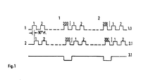
- the pulse series 1 and 2 are assigned to a track 1.1 and 2.1, respectively, while the reference pulse (zero pulse) is located on a third track 3.1.
- Each pulse series consists of pulse sequences with bsw. a pulse number of 200 pulses / revolution of the pulse disc of the incremental angle encoder.
- a direction signal e.g. direction of rotation
- the pulse series 1 and 2 are offset by 90 ° el. And evaluated in a logic circuit.
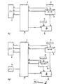
- an incremental angle step encoder 8 is connected to a control logic 4 via the outputs 5, 6.
- the outputs 9, 10 of the control logic are routed to a counter 11 to which a read-only memory 13 is connected via an input 12.
- a larger-smaller comparator 14 is above his Input 16 to the counter 11, and via its input 15 to a read-only memory 17 for error limits.
- the output 18 of the larger-smaller comparator is fed back to the control logic 4.
- the control logic 4 contains, not shown, among other things. a fault message memory, two memories for hiding a first, incomplete pulse sequence within a measurement cycle, and a logic operation for the control signals of the counter 11.
- the adjustable number of pulses / revolution of the incremental angle encoder 8 from bsw. 200 pulses are entered into counter 11. With the pulses of pulse series 1 on track 1.1, counter 11 then counts down. When the zero pulse arrives at the end of the rotation of the pulse disc of the angle step encoder, the counter is stopped and the counter reading is compared with the adjustable error limit of a read-only memory 17. If the error limit has not been observed, the control logic 4 outputs an error signal via its output 19.
- the counter 11 is reset and the next cycle begins with the counting of the pulses of pulse series 2 on track 2.1.
- the pulse number of pulse series 1 and 2 is therefore monitored with every second revolution of the pulse disk of the angular step encoder.
- the zero pulse is monitored with the help of a timing element with each revolution of the pulse disc of the angle step encoder. If there is no zero pulse after the set time, then the control logic 4 also outputs a fault signal via the output 19. The timer is restarted for the next cycle. The monitoring is hidden when the direction of rotation changes.
- FIG. 2 Another embodiment is shown in FIG. 2.
- the block diagram is constructed analogously to the block diagram according to FIG. 1.
- a second counter 20 which is connected to the control logic 4 via the outputs 21, 22 and whose output is connected to the input 15 of the larger-smaller comparator 25.
- the control logic 4 is connected on the input side to a clock generator 24, which consists of a quartz-controlled oscillator, and is used to generate the reference pulse.
- the measuring cycle for counting the pulses can be done in two ways:
- the pulse series 1 and 2 or tracks 1.1 and 2.1 of the angular step encoder are each assigned a counter 11 or counter 20 in which the pulse sequences are counted.
- the two counter readings are compared with one another in the larger-smaller comparator 25, and in the event of inequality, an interference signal is output via the output 19 of the control logic 4.
- the angular pacemaker uses only one counter, and the pulse trains are monitored in such a way that the counter cyclically counts up a pulse train of pulse train 1 and then counts down the following pulse train of pulse train 2, so that when the reference pulse appears from clock 24 and more correctly Number of pulses, the counter has a counter reading of zero. Deviations from this again trigger an interference pulse via the output 19 of the control logic 4.
- the aforementioned circuit arrangements work independently of the size of the frequency of the pulse trains to be monitored.
Landscapes
- Physics & Mathematics (AREA)
- General Physics & Mathematics (AREA)
- Transmission And Conversion Of Sensor Element Output (AREA)
- Electrotherapy Devices (AREA)
Applications Claiming Priority (2)
| Application Number | Priority Date | Filing Date | Title |
|---|---|---|---|
| DE19803005149 DE3005149A1 (de) | 1980-02-12 | 1980-02-12 | Verfahren zur ueberwachung von impulsfolgen |
| DE3005149 | 1980-02-12 |
Publications (2)
| Publication Number | Publication Date |
|---|---|
| EP0033902A2 true EP0033902A2 (fr) | 1981-08-19 |
| EP0033902A3 EP0033902A3 (fr) | 1982-07-14 |
Family
ID=6094390
Family Applications (1)
| Application Number | Title | Priority Date | Filing Date |
|---|---|---|---|
| EP81100606A Withdrawn EP0033902A3 (fr) | 1980-02-12 | 1981-01-28 | Méthode de contrôle d'une série d'impulsions |
Country Status (2)
| Country | Link |
|---|---|
| EP (1) | EP0033902A3 (fr) |
| DE (1) | DE3005149A1 (fr) |
Cited By (6)
| Publication number | Priority date | Publication date | Assignee | Title |
|---|---|---|---|---|
| EP0125413A2 (fr) * | 1983-03-22 | 1984-11-21 | Siemens Aktiengesellschaft | Dispositif pas-à-pas de mesure de parcours |
| DE3431841A1 (de) * | 1984-08-30 | 1986-03-13 | Robert Bosch Gmbh, 7000 Stuttgart | Verfahren zur ueberwachung eines digitalen inkrementalen messwertaufnehmers |
| EP0311947A2 (fr) * | 1987-10-12 | 1989-04-19 | Olympus Optical Co., Ltd. | Dispositif de détection d'erreur de comptage pour instruments de mesure de type compteurs |
| EP1593971A3 (fr) * | 2004-05-04 | 2006-01-18 | Krones AG | Dispositif et méthode pour vérifier le fonctionnement d'un codeur angulaire |
| WO2010112984A1 (fr) * | 2009-03-31 | 2010-10-07 | Atmel Corporation | Ensemble de circuits de filtrage d'un décodeur de quadrature pour la commande d'un moteur |
| WO2014204919A1 (fr) * | 2013-06-20 | 2014-12-24 | Allegro Microsystems, Llc | Système et procédé de réalisation de codage de signal, représentatif d'une région de signature dans une cible, et représentatif d'un sens de rotation |
Citations (3)
| Publication number | Priority date | Publication date | Assignee | Title |
|---|---|---|---|---|
| GB1096651A (en) * | 1964-01-17 | 1967-12-29 | Davy & United Eng Co Ltd | Control apparatus and method |
| GB1219757A (en) * | 1967-10-06 | 1971-01-20 | Davey And United Engineering C | Protection circuits including transducers especially for counting arrangements |
| GB1302762A (fr) * | 1970-02-06 | 1973-01-10 |
-
1980
- 1980-02-12 DE DE19803005149 patent/DE3005149A1/de not_active Ceased
-
1981
- 1981-01-28 EP EP81100606A patent/EP0033902A3/fr not_active Withdrawn
Patent Citations (3)
| Publication number | Priority date | Publication date | Assignee | Title |
|---|---|---|---|---|
| GB1096651A (en) * | 1964-01-17 | 1967-12-29 | Davy & United Eng Co Ltd | Control apparatus and method |
| GB1219757A (en) * | 1967-10-06 | 1971-01-20 | Davey And United Engineering C | Protection circuits including transducers especially for counting arrangements |
| GB1302762A (fr) * | 1970-02-06 | 1973-01-10 |
Cited By (9)
| Publication number | Priority date | Publication date | Assignee | Title |
|---|---|---|---|---|
| EP0125413A2 (fr) * | 1983-03-22 | 1984-11-21 | Siemens Aktiengesellschaft | Dispositif pas-à-pas de mesure de parcours |
| EP0125413A3 (en) * | 1983-03-22 | 1988-01-20 | Siemens Aktiengesellschaft Berlin Und Munchen | Incremental length measuring device |
| DE3431841A1 (de) * | 1984-08-30 | 1986-03-13 | Robert Bosch Gmbh, 7000 Stuttgart | Verfahren zur ueberwachung eines digitalen inkrementalen messwertaufnehmers |
| EP0311947A2 (fr) * | 1987-10-12 | 1989-04-19 | Olympus Optical Co., Ltd. | Dispositif de détection d'erreur de comptage pour instruments de mesure de type compteurs |
| EP0311947A3 (en) * | 1987-10-12 | 1990-12-19 | Olympus Optical Co., Ltd. | Count error detecting device for count type measuring instruments |
| EP1593971A3 (fr) * | 2004-05-04 | 2006-01-18 | Krones AG | Dispositif et méthode pour vérifier le fonctionnement d'un codeur angulaire |
| WO2010112984A1 (fr) * | 2009-03-31 | 2010-10-07 | Atmel Corporation | Ensemble de circuits de filtrage d'un décodeur de quadrature pour la commande d'un moteur |
| WO2014204919A1 (fr) * | 2013-06-20 | 2014-12-24 | Allegro Microsystems, Llc | Système et procédé de réalisation de codage de signal, représentatif d'une région de signature dans une cible, et représentatif d'un sens de rotation |
| US9664748B2 (en) | 2013-06-20 | 2017-05-30 | Allegro Microsystems, Llc | Systems and methods for providing signal encoding representative of a signature region in a target |
Also Published As
| Publication number | Publication date |
|---|---|
| DE3005149A1 (de) | 1981-08-20 |
| EP0033902A3 (fr) | 1982-07-14 |
Similar Documents
| Publication | Publication Date | Title |
|---|---|---|
| EP0246404B1 (fr) | Méthode de mesure | |
| EP1225427B1 (fr) | Capteur de rotation | |
| EP0231474B1 (fr) | Dispositif de détermination du déplacement absolue | |
| DE2633846C2 (de) | Numerische Regeleinrichtung | |
| DE2837842C2 (fr) | ||
| DE1538513B2 (de) | Anordnung zur numerischen steuerung der verstellung von bewegbaren elementen, insbesondere fuer die verstellung des werkstueck- oder werkzeugtraegers einer werkzeugmaschine | |
| EP0392182B1 (fr) | Procédé et circuit pour l'évaluation d'un débit continu de marques temporelles | |
| EP0033902A2 (fr) | Méthode de contrôle d'une série d'impulsions | |
| EP2116814B1 (fr) | Dispositif de mesure destiné à la détermination d'une position et/ou d'une vitesse | |
| EP0805382A1 (fr) | Dispositif de diagnostique pour une machine à commande électronique avec clés de combinaison d'états mesurés de la machine | |
| DE4035520C2 (de) | Verfahren und Anordnung zur Messung der Geschwindigkeit eines Fahrzeuges | |
| EP3035000A1 (fr) | Dispositif et procede de verification d'un signal de travail d'un dispositif de mesure de position | |
| DE4003532C2 (de) | Kapazitive Doppelbogenkontrolleinrichtung | |
| DE102007004358A1 (de) | Positionsmesssystem mit Nullspur | |
| DE4009749C2 (fr) | ||
| DE4013583C2 (fr) | ||
| DE3434608A1 (de) | Wegmesseinrichtung | |
| DE3509682C2 (fr) | ||
| DE3725128C2 (fr) | ||
| DE1463283C3 (fr) | ||
| DE19604968C2 (de) | Verfahren zum Prüfen von inkrementalen Meßsystemen und Prüfgerät zur Durchführung des Verfahrens | |
| DE69400786T2 (de) | Verfahren und Vorrichtung zum Überwachen von Signalen von Wandlern und optischen Encodern | |
| EP0342375B1 (fr) | Procédé pour contrôler les circuits rompus dans les lignes de raccordement de sondes linéaires à impulsion d'un capteur de rotation et circuit pour l'utilisation du procédé | |
| DE3829636C2 (de) | Positionserfassungssystem | |
| DE3431841C2 (fr) |
Legal Events
| Date | Code | Title | Description |
|---|---|---|---|
| PUAI | Public reference made under article 153(3) epc to a published international application that has entered the european phase |
Free format text: ORIGINAL CODE: 0009012 |
|
| AK | Designated contracting states |
Designated state(s): BE CH FR IT |
|
| PUAL | Search report despatched |
Free format text: ORIGINAL CODE: 0009013 |
|
| AK | Designated contracting states |
Designated state(s): BE CH FR IT |
|
| 17P | Request for examination filed |
Effective date: 19821223 |
|
| STAA | Information on the status of an ep patent application or granted ep patent |
Free format text: STATUS: THE APPLICATION IS DEEMED TO BE WITHDRAWN |
|
| 18D | Application deemed to be withdrawn |
Effective date: 19840918 |
|
| RIN1 | Information on inventor provided before grant (corrected) |
Inventor name: ORLOWSKI, PETER, DIPL.-ING. |