EP0033902A2 - Method for the surveillance of pulse trains - Google Patents
Method for the surveillance of pulse trains Download PDFInfo
- Publication number
- EP0033902A2 EP0033902A2 EP81100606A EP81100606A EP0033902A2 EP 0033902 A2 EP0033902 A2 EP 0033902A2 EP 81100606 A EP81100606 A EP 81100606A EP 81100606 A EP81100606 A EP 81100606A EP 0033902 A2 EP0033902 A2 EP 0033902A2
- Authority
- EP
- European Patent Office
- Prior art keywords
- pulse
- pulses
- counter
- series
- reference pulse
- Prior art date
- Legal status (The legal status is an assumption and is not a legal conclusion. Google has not performed a legal analysis and makes no representation as to the accuracy of the status listed.)
- Withdrawn
Links
Images
Classifications
-
- G—PHYSICS
- G01—MEASURING; TESTING
- G01D—MEASURING NOT SPECIALLY ADAPTED FOR A SPECIFIC VARIABLE; ARRANGEMENTS FOR MEASURING TWO OR MORE VARIABLES NOT COVERED IN A SINGLE OTHER SUBCLASS; TARIFF METERING APPARATUS; MEASURING OR TESTING NOT OTHERWISE PROVIDED FOR
- G01D5/00—Mechanical means for transferring the output of a sensing member; Means for converting the output of a sensing member to another variable where the form or nature of the sensing member does not constrain the means for converting; Transducers not specially adapted for a specific variable
- G01D5/12—Mechanical means for transferring the output of a sensing member; Means for converting the output of a sensing member to another variable where the form or nature of the sensing member does not constrain the means for converting; Transducers not specially adapted for a specific variable using electric or magnetic means
- G01D5/244—Mechanical means for transferring the output of a sensing member; Means for converting the output of a sensing member to another variable where the form or nature of the sensing member does not constrain the means for converting; Transducers not specially adapted for a specific variable using electric or magnetic means influencing characteristics of pulses or pulse trains; generating pulses or pulse trains
- G01D5/24457—Failure detection
- G01D5/24461—Failure detection by redundancy or plausibility
-
- G—PHYSICS
- G01—MEASURING; TESTING
- G01D—MEASURING NOT SPECIALLY ADAPTED FOR A SPECIFIC VARIABLE; ARRANGEMENTS FOR MEASURING TWO OR MORE VARIABLES NOT COVERED IN A SINGLE OTHER SUBCLASS; TARIFF METERING APPARATUS; MEASURING OR TESTING NOT OTHERWISE PROVIDED FOR
- G01D5/00—Mechanical means for transferring the output of a sensing member; Means for converting the output of a sensing member to another variable where the form or nature of the sensing member does not constrain the means for converting; Transducers not specially adapted for a specific variable
- G01D5/12—Mechanical means for transferring the output of a sensing member; Means for converting the output of a sensing member to another variable where the form or nature of the sensing member does not constrain the means for converting; Transducers not specially adapted for a specific variable using electric or magnetic means
- G01D5/244—Mechanical means for transferring the output of a sensing member; Means for converting the output of a sensing member to another variable where the form or nature of the sensing member does not constrain the means for converting; Transducers not specially adapted for a specific variable using electric or magnetic means influencing characteristics of pulses or pulse trains; generating pulses or pulse trains
- G01D5/245—Mechanical means for transferring the output of a sensing member; Means for converting the output of a sensing member to another variable where the form or nature of the sensing member does not constrain the means for converting; Transducers not specially adapted for a specific variable using electric or magnetic means influencing characteristics of pulses or pulse trains; generating pulses or pulse trains using a variable number of pulses in a train
- G01D5/2454—Encoders incorporating incremental and absolute signals
- G01D5/2455—Encoders incorporating incremental and absolute signals with incremental and absolute tracks on the same encoder
- G01D5/2457—Incremental encoders having reference marks
Definitions
- the invention relates to a method for monitoring the pulse number of periodically occurring pulse sequences separated by a reference pulse in a pulse generator, in particular in an incremental angle stepper with at least one pulse series and adjustable pulse number / revolution.
- the incremental measuring device works on an incremental scale, which divides the measuring section into path elements of the same size.
- the transducer signals every path element.
- the pulses are summed to generate the measured value.
- a direction signal (e.g. direction of rotation) is formed by two series of pulses offset by 90 ° el., Which are evaluated in a logic circuit.
- Incremental measuring devices are used in a variety of ways, e.g. in the steel industry for top roller adjustments and shifters on roll stands, the control of saws and shears.
- Incremental measuring devices are simple and inexpensive to set up and use. However, they have the disadvantage that they are very sensitive to interference pulses, for example. can get into the counter circuit via the power supply and advance the counter so that incorrect measurements occur.
- Incremental angle encoders with two pulse series have become known, in which only the failure of one pulse series is recognized, but disturbances in the pulse series formation, such as the absence of pulses or the occurrence of additional pulses in a pulse series, are not detected. However, the detection of such errors is particularly important. So is bsw. the safe functioning of a rolling mill system depends on the perfect detection of the speed, the speed, as well as the path and the coil diameter, whereby the individual criteria are recorded with the help of incremental angle encoders.
- the invention has for its object to avoid interference in pulse generators due to incorrect number of pulses, and thus to improve the functional reliability of the pulse generator.
- This object is achieved in that the number of pulses is entered as a setpoint in a counter, and the pulses are counted when the pulse train expires, that a setpoint / actual value comparison takes place in a comparator when the reference pulse arrives, and a fault message memory if the number of pulses is incorrect is set to output a fault signal and that the reference pulse is monitored.
- An expedient development of the invention is that for counting the pulses of two pulse series, a counter is cyclically connected to a first pulse series and then to a second pulse series, and that the switching is carried out by the reference pulse.
- a further useful embodiment of the invention consists in that the pulse sequences of two pulse series are alternately entered into a forward / backward counter for counting the pulses, and are queried with the reference pulse.
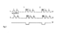
- the pulse series 1 and 2 are assigned to a track 1.1 and 2.1, respectively, while the reference pulse (zero pulse) is located on a third track 3.1.
- Each pulse series consists of pulse sequences with bsw. a pulse number of 200 pulses / revolution of the pulse disc of the incremental angle encoder.
- a direction signal e.g. direction of rotation
- the pulse series 1 and 2 are offset by 90 ° el. And evaluated in a logic circuit.
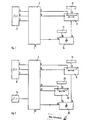
- an incremental angle step encoder 8 is connected to a control logic 4 via the outputs 5, 6.
- the outputs 9, 10 of the control logic are routed to a counter 11 to which a read-only memory 13 is connected via an input 12.
- a larger-smaller comparator 14 is above his Input 16 to the counter 11, and via its input 15 to a read-only memory 17 for error limits.
- the output 18 of the larger-smaller comparator is fed back to the control logic 4.
- the control logic 4 contains, not shown, among other things. a fault message memory, two memories for hiding a first, incomplete pulse sequence within a measurement cycle, and a logic operation for the control signals of the counter 11.
- the adjustable number of pulses / revolution of the incremental angle encoder 8 from bsw. 200 pulses are entered into counter 11. With the pulses of pulse series 1 on track 1.1, counter 11 then counts down. When the zero pulse arrives at the end of the rotation of the pulse disc of the angle step encoder, the counter is stopped and the counter reading is compared with the adjustable error limit of a read-only memory 17. If the error limit has not been observed, the control logic 4 outputs an error signal via its output 19.
- the counter 11 is reset and the next cycle begins with the counting of the pulses of pulse series 2 on track 2.1.
- the pulse number of pulse series 1 and 2 is therefore monitored with every second revolution of the pulse disk of the angular step encoder.
- the zero pulse is monitored with the help of a timing element with each revolution of the pulse disc of the angle step encoder. If there is no zero pulse after the set time, then the control logic 4 also outputs a fault signal via the output 19. The timer is restarted for the next cycle. The monitoring is hidden when the direction of rotation changes.
- FIG. 2 Another embodiment is shown in FIG. 2.
- the block diagram is constructed analogously to the block diagram according to FIG. 1.
- a second counter 20 which is connected to the control logic 4 via the outputs 21, 22 and whose output is connected to the input 15 of the larger-smaller comparator 25.
- the control logic 4 is connected on the input side to a clock generator 24, which consists of a quartz-controlled oscillator, and is used to generate the reference pulse.
- the measuring cycle for counting the pulses can be done in two ways:
- the pulse series 1 and 2 or tracks 1.1 and 2.1 of the angular step encoder are each assigned a counter 11 or counter 20 in which the pulse sequences are counted.
- the two counter readings are compared with one another in the larger-smaller comparator 25, and in the event of inequality, an interference signal is output via the output 19 of the control logic 4.
- the angular pacemaker uses only one counter, and the pulse trains are monitored in such a way that the counter cyclically counts up a pulse train of pulse train 1 and then counts down the following pulse train of pulse train 2, so that when the reference pulse appears from clock 24 and more correctly Number of pulses, the counter has a counter reading of zero. Deviations from this again trigger an interference pulse via the output 19 of the control logic 4.
- the aforementioned circuit arrangements work independently of the size of the frequency of the pulse trains to be monitored.
Landscapes
- Physics & Mathematics (AREA)
- General Physics & Mathematics (AREA)
- Transmission And Conversion Of Sensor Element Output (AREA)
- Electrotherapy Devices (AREA)
Abstract
Die Erfindung beschreibt ein Verfahren zur Überwachung der Impulszahl periodisch auftretender, durch einen Referenzimpuls getrennter Impulsfolgen bei einem Impulsgeber, insbesondere bei einem inkrementalen Winkelschrittgeber. Erfindungsgemäss geschieht dies so, dass die Impulszahl als Sollwert in einen Zähler eingegeben wird, und die Impulse mit Ablauf der Impulsfolge gezählt werden, dass in einem Vergleicher beim Eintreffen des Referenzimpulses ein Sollwert-Istwert-Vergleich erfolgt, und bei inkorrekter Impulszahl ein Störmeldespeicher gesetzt wird zur Ausgabe eines Störmeldesignals, und dass der Refezrenzimpuls überwacht wird.The invention describes a method for monitoring the pulse number of periodically occurring pulse sequences separated by a reference pulse in a pulse generator, in particular in an incremental angular step encoder. According to the invention, this is done in such a way that the number of pulses is entered as a setpoint in a counter, and the pulses are counted as the pulse sequence expires, that a setpoint / actual value comparison takes place in a comparator when the reference pulse arrives, and a fault message memory is set if the number of pulses is incorrect to output a fault signal and that the reference pulse is monitored.
Description
Die Erfindung bezieht sich auf ein Verfahren zur Überwachung der Impulszahl periodisch auftretender, durch einen Referenzimpuls getrennter Impulsfolgen bei einem Impulsgeber, insbesondere bei einem inkrementalen Winkelschrittgeber mit mindestens einer Impulsreihe und einstellbarer Impulszahl/Umdrehung.The invention relates to a method for monitoring the pulse number of periodically occurring pulse sequences separated by a reference pulse in a pulse generator, in particular in an incremental angle stepper with at least one pulse series and adjustable pulse number / revolution.
Durch die zunehmende Automatisierung von Produktionsprozessen in der Industrie und durch die Fertigung von Produkten mit kleinen Fertigungstoleranzen werden steigende Anforderungen an die Regelung und Steuerung der hier verwendeten Antriebe gestellt. Das hat zur Folge, daß die dazu benutzten Lagemeßeinrichtungen genau und sicher funktionieren müssen.Due to the increasing automation of production processes in industry and the manufacture of products with small manufacturing tolerances, increasing demands are made on the regulation and control of the drives used here. The consequence of this is that the position measuring devices used for this purpose must function precisely and safely.
Wegen des vermehrten Einsatzes der digitalen Informations- verarbeitung bei Automatisierungseinrichtungen gewinnen digitale elektronische Meßeinrichtungen zunehmend an Bedeutung.Due to the increased use of digital information - processing in automation equipment to win digital electronic measuring devices increasingly important.
Es gibt absolute und inkrementale Verfahren, nach denen digitale Meßeinrichtungen arbeiten.There are absolute and incremental methods according to which digital measuring devices work.
Die inkrementale Meßeinrichtung arbeitet mit einem inkrementalen Maßstab, der die Meßstrecke in gleich große Wegelemente unterteilt. Der Aufnehmer signalisiert jedes Wegelement. Zur Erzeugung des Meßwertes werden die Impulse summiert. Die Bildung eines Richtungssignals (z.B. Drehrichtung) geschieht durch zwei um 90° el. gegeneinander versetzte Impulsreihen, die in einer logischen Schaltung ausgewertet werden.The incremental measuring device works on an incremental scale, which divides the measuring section into path elements of the same size. The transducer signals every path element. The pulses are summed to generate the measured value. A direction signal (e.g. direction of rotation) is formed by two series of pulses offset by 90 ° el., Which are evaluated in a logic circuit.
Inkrementale Meßeinrichtungen werden vielfältig eingesetzt so z.B. in der Stahlindustrie bei Oberwalzenanstellungen und Verschiebern an Walzgerüsten, der Steuerung von Sägen und Scheren.Incremental measuring devices are used in a variety of ways, e.g. in the steel industry for top roller adjustments and shifters on roll stands, the control of saws and shears.
Inkrementale Meßeinrichtungen sind einfach und preiswert im Aufbau und in der Anwendung. Sie haben aber den Nachteil, daß sie sehr empfindlich sind gegenüber Störimpulsen, die bsw. über die Stromversorgung in die Zählerschaltung gelangen können und den Zähler weiterschalten, so daß es zu Fehlmessungen kommt.Incremental measuring devices are simple and inexpensive to set up and use. However, they have the disadvantage that they are very sensitive to interference pulses, for example. can get into the counter circuit via the power supply and advance the counter so that incorrect measurements occur.
Es sind inkrementale Winkelschrittgeber mit zwei Impulsreihen bekanntgeworden, bei denen nur der Ausfall einer Impulsreihe erkannt wird, Störungen bei der Impulsreihenbildung aber, wie das Fehlen von Impulsen oder das Auftreten zusätzlicher Impulse in einer Impulsreihe, nicht erfaßt werden. Die Erfassung derartiger Fehler .ist aber besonders wichtig. So ist bsw. die sichere Funktion einer Walzwerksanlage von der einwandfreien Erfassung der Drehzahl, der Geschwindigkeit, sowie des Weges und des Bunddurchmessers abhängig, wobei die einzelnen Kriterien mit Hilfe von inkrementalen Winkelschrittgebern erfaßt werden.Incremental angle encoders with two pulse series have become known, in which only the failure of one pulse series is recognized, but disturbances in the pulse series formation, such as the absence of pulses or the occurrence of additional pulses in a pulse series, are not detected. However, the detection of such errors is particularly important. So is bsw. the safe functioning of a rolling mill system depends on the perfect detection of the speed, the speed, as well as the path and the coil diameter, whereby the individual criteria are recorded with the help of incremental angle encoders.
Der Erfindung liegt die Aufgabe zugrunde, Störungen bei Impulsgebern infolge inkorrekter Impulszahl zu vermeiden, und damit die Funktionssicherheit der Impulsgeber zu verbesseren.The invention has for its object to avoid interference in pulse generators due to incorrect number of pulses, and thus to improve the functional reliability of the pulse generator.
Diese Aufgabe wird erfindungsgemäß dadurch gelöst, daß die Impulszahl als Sollwert in einen Zähler eingegeben wird, und die Impulse mit Ablauf der Impulsfolge gezählt werden, daß in einem Vergleicher beim Eintreffen des Referenzimpulses ein Sollwert - Istwert - Vergleich erfolgt, und bei inkorrekter Impulszahl ein Störmeldespeicher gesetzt wird zur Ausgabe eines Störmeldesignales, und daß der Referenzimpuls überwacht wird.This object is achieved in that the number of pulses is entered as a setpoint in a counter, and the pulses are counted when the pulse train expires, that a setpoint / actual value comparison takes place in a comparator when the reference pulse arrives, and a fault message memory if the number of pulses is incorrect is set to output a fault signal and that the reference pulse is monitored.
Eine zweckmäßige Weiterbildung der Erfindung besteht darin, daß zum Zählen der Impulse zweier Impulsreihen ein Zähler zyklisch an eine erste Impulsreihe angeschaltet wird, und danach an eine zweite Impulsreihe, und daß die Umschaltung durch den Referenzimpuls erfolgt.An expedient development of the invention is that for counting the pulses of two pulse series, a counter is cyclically connected to a first pulse series and then to a second pulse series, and that the switching is carried out by the reference pulse.
Eine weitere sinnvolle Ausbildung der Erfindung besteht darin, daß zum Zählen der Impulse die Impulsfolgen zweier Impulsreihen alternierend in einen Vorwärts - Rückwärts - Zähler eingegeben, und mit dem Referenzimpuls abgefragt werden.A further useful embodiment of the invention consists in that the pulse sequences of two pulse series are alternately entered into a forward / backward counter for counting the pulses, and are queried with the reference pulse.
Die mit der Erfindung erzielten Vorteile bestehen insbesondere darin, daß mit einfachen Mitteln die Funktionssicherheit des inkrementalen Impulsgebers verbessert wurde, so daß diese Impulsgeber auch für Meßaufgaben herangezogen werden können, wie sie sonst nur von Impulsgebern mit höherem technischen Aufwand bewältigt werden.The advantages achieved by the invention are, in particular, that the functional reliability of the incremental pulse generator has been improved with simple means, so that these pulse generators can also be used for measuring tasks which are otherwise only handled by pulse generators with a higher level of technical complexity.
Zwei Ausführungsbeispiele der Erfindung sind in der Zeichnung dargestellt und werden im folgenden näher beschrieben.Two embodiments of the invention are shown in the drawing and are described in more detail below.
Es zeigt:
- Fig. 1 ein Impulsdiagramm eines inkrementalen Winkelschrittgebers;
- Fig. 2 ein Blockschaltbild einer Einrichtung zur Überwachung der Impulszahl eines inkrementalen Winkelschrittgebers nach Fig. 1;
- Fig. 3 ein Blockschaltbild analog Fig. 2.mit zwei Zählern und einem zusätzlichen Taktgeber.
- Figure 1 is a timing diagram of an incremental angle encoder.
- FIG. 2 shows a block diagram of a device for monitoring the pulse number of an incremental angular step encoder according to FIG. 1;
- Fig. 3 is a block diagram analogous to Fig. 2. with two counters and an additional clock.
Gemäß. dem Impulsdiagramm nach Fig. 1 für einen inkrementalen Winkelschrittgeber sind die Impulsreihen 1 und 2, einer Spur 1.1 bzw. 2.1 zugeordnet, während sich auf einer dritten Spur 3.1 der Referenzimpuls (Nullimpuls) befindet. Jede Impulsreihe besteht aus Impulsfolgen mit bsw. einer Impulszahl von 200 Impulsen/Umdrehung der Impulsscheibe des inkrementalen Winkelschrittgebers. Zur Bildung eines Richtungssignals (z.B. Drehrichtung) werden die Impulsreihen 1 und 2 um 90° el. gegeneinander versetzt und in einer logischen Schaltung ausgewertet.According to. 1 for an incremental angle step encoder, the
In dem in Fig. 2 dargestellen Blockschaltbild ist ein inkrementaler Winkelschrittgeber 8 über die Ausgänge 5, 6, mit einer Steuerlogik 4 verbunden. Die Ausgänge 9, 10 der Steuerlogik sind auf einen Zähler 11 geführt, an dem über einen Eingang 12 ein,Festwertspeicher 13 angeschlossen ist. Ein Größer-Kleiner-Vergleicher 14 ist über seinen Eingang 16 mit dem Zähler 11, und über seinen Eingang 15 mit einem Festwertspeicher 17 für Fehlergrenzen, verbunden. Der Ausgang 18 des Größer-Kleiner-Vergleichers ist auf die Steuerlogik 4 zurückgeführt.In the block diagram shown in FIG. 2, an incremental angle step encoder 8 is connected to a control logic 4 via the
Die Steuerlogik 4 enthält, nicht näher dargestellt u.a. einen Störmeldespeicher, zwei Speicher zum Ausblenden einer ersten, unvollständigen Impulsfolge innerhalb eines Messzyklus sowie eine logische Verknüpfung für die Steuersignale des Zählers 11.The control logic 4 contains, not shown, among other things. a fault message memory, two memories for hiding a first, incomplete pulse sequence within a measurement cycle, and a logic operation for the control signals of the counter 11.
Die vorgenannte Schaltungsanordnung funktioniert wie folgt:The aforementioned circuit arrangement works as follows:
Die einstellbare Impulszahl/Umdrehung des inkrementalen Winkelschrittgebers 8 von bsw. 200 Impulsen wird in den Zähler 11 eingegeben. Mit den Impulsen der Impulsreihe 1 auf der Spur 1.1 zählt dann der Zähler 11 rückwärts. Beim Eintreffen des Nullimpulses am Ende der Umdrehung der Impulsscheibe des Winkelschrittgebers, wird der Zähler gestoppt, und der Zählerstand mit der einstellbaren Fehlergrenze eines Festwertspeichers 17 verglichen. Wurde die Fehlergrenze nicht eingehalten, dann gibt die Steuer- - logik 4 über ihren Ausgang 19 ein Störmeldesignal aus.The adjustable number of pulses / revolution of the incremental angle encoder 8 from bsw. 200 pulses are entered into counter 11. With the pulses of
Der Zähler 11 wird neu gesetzt, und es beginnt der nächste Zyklus mit der Zählung der Impulse der Impulsreihe 2 auf der Spur 2.1. Es wird also die Impulszahl der Impulsreihen 1 und 2 bei jeder zweiten Umdrehung der Impulsscheibe des Winkelschrittgebers überwacht.The counter 11 is reset and the next cycle begins with the counting of the pulses of
Die Überwachung des Nullimpulses geschieht bei jeder Umdrehung der Impulsscheibe des Winkelschrittgebers mit Hilfe eines Zeitgliedes. Erfolgt nach der eingestellten Zeit kein Nullimpuls, dann gibt die Steuerlogik 4 über den Ausgang 19 ebenfalls ein Störmeldesignal aus. Für den nächsten Zyklus wird das Zeitglied neu gestartet. Bei Drehrichtungswechsel wird die Überwachung ausgeblendet.The zero pulse is monitored with the help of a timing element with each revolution of the pulse disc of the angle step encoder. If there is no zero pulse after the set time, then the control logic 4 also outputs a fault signal via the
Ein weiteres Ausführungsbeispiel ist in Fig. 2 dargestellt. Das Blockschaltbild ist analog dem Blockschaltbild nach Fig. 1 aufgebaut. An die Stelle des Festwertspeichers 17 tritt hier ein zweiter Zähler 20, der mit der Steuerlogik 4 über die Ausgänge 21, 22 verbunden ist, und dessen Ausgang auf den Eingang 15 des Größer-Kleiner-Vergleichers 25 geführt ist. Desweiteren ist die Steuerlogik 4 eingangsseitig mit 'einem Taktgeber 24 verbunden, der aus einem quarzgesteuerten Oszillator besteht, und zur Erzeugung des Referenzimpulses dient.Another embodiment is shown in FIG. 2. The block diagram is constructed analogously to the block diagram according to FIG. 1. In place of the read-
Der Messzyklus zur Zählung der Impulse kann auf zweifache Weise erfolgen:The measuring cycle for counting the pulses can be done in two ways:
Zum einen sind den Impulsreihen 1 und 2 bzw. Spuren 1.1 und 2.1 des Winkelschrittgebers jeweils ein Zähler 11 bzw. Zähler 20 zugeordnet, in welche die Impulsfolgen gezählt werden. Bei Erscheinen des Referenzimpulses werden beide Zählerstände in dem Größer-Kleiner-Vergleicher 25 miteinander verglichen, und bei Ungleichheit eine Störsignal über den Ausgang 19 der Steuerlogik 4 ausgegeben.On the one hand, the
Zum anderen wird für die Impulsreihen 1 und 2 bzw. Spuren 1.1 und 2.1. des Winkelschrittgebers nur ein Zähler verwendet, und eine Überwachung der Impulsfolgen so erfolgt, in dem der Zähler zyklisch eine Impulsfolge der Impulsreihe 1 vorwärts zählt und anschließend die folgende Impulsfolge der Impulsreihe 2 rückwärts zählt, so daß bei Erscheinen des Referenzimpulses aus dem Taktgeber 24 und korrekter Impulszahl, der Zähler den Zählerstand Null aufweist. Abweichungen hiervon lösen wieder einen Störimpuls über den Ausgang'19 der Steuerlogik 4 aus.On the other hand, for
Die vorgenannten Schaltungsanordnungen funktioniern unabhängig von der Größe der Frequenz der zu überwachenden Impulsfolgen.The aforementioned circuit arrangements work independently of the size of the frequency of the pulse trains to be monitored.
Claims (5)
Applications Claiming Priority (2)
| Application Number | Priority Date | Filing Date | Title |
|---|---|---|---|
| DE3005149 | 1980-02-12 | ||
| DE19803005149 DE3005149A1 (en) | 1980-02-12 | 1980-02-12 | METHOD FOR MONITORING IMPULSE SEQUENCES |
Publications (2)
| Publication Number | Publication Date |
|---|---|
| EP0033902A2 true EP0033902A2 (en) | 1981-08-19 |
| EP0033902A3 EP0033902A3 (en) | 1982-07-14 |
Family
ID=6094390
Family Applications (1)
| Application Number | Title | Priority Date | Filing Date |
|---|---|---|---|
| EP81100606A Withdrawn EP0033902A3 (en) | 1980-02-12 | 1981-01-28 | Method for the surveillance of pulse trains |
Country Status (2)
| Country | Link |
|---|---|
| EP (1) | EP0033902A3 (en) |
| DE (1) | DE3005149A1 (en) |
Cited By (6)
| Publication number | Priority date | Publication date | Assignee | Title |
|---|---|---|---|---|
| DE3431841A1 (en) * | 1984-08-30 | 1986-03-13 | Robert Bosch Gmbh, 7000 Stuttgart | Method for monitoring a digital incremental measurement-value pickup |
| EP0125413A3 (en) * | 1983-03-22 | 1988-01-20 | Siemens Aktiengesellschaft Berlin Und Munchen | Incremental length measuring device |
| EP0311947A3 (en) * | 1987-10-12 | 1990-12-19 | Olympus Optical Co., Ltd. | Count error detecting device for count type measuring instruments |
| EP1593971A3 (en) * | 2004-05-04 | 2006-01-18 | Krones AG | Device and method for the verification of the functionality of an angular encoder |
| WO2010112984A1 (en) * | 2009-03-31 | 2010-10-07 | Atmel Corporation | Quadrature decoder filtering circuitry for motor control |
| WO2014204919A1 (en) * | 2013-06-20 | 2014-12-24 | Allegro Microsystems, Llc | System and method for providing signal encoding representative of a signature region in a target and of a direction of rotation |
Family Cites Families (3)
| Publication number | Priority date | Publication date | Assignee | Title |
|---|---|---|---|---|
| GB1096651A (en) * | 1964-01-17 | 1967-12-29 | Davy & United Eng Co Ltd | Control apparatus and method |
| GB1219757A (en) * | 1967-10-06 | 1971-01-20 | Davey And United Engineering C | Protection circuits including transducers especially for counting arrangements |
| GB1302762A (en) * | 1970-02-06 | 1973-01-10 |
-
1980
- 1980-02-12 DE DE19803005149 patent/DE3005149A1/en not_active Ceased
-
1981
- 1981-01-28 EP EP81100606A patent/EP0033902A3/en not_active Withdrawn
Cited By (7)
| Publication number | Priority date | Publication date | Assignee | Title |
|---|---|---|---|---|
| EP0125413A3 (en) * | 1983-03-22 | 1988-01-20 | Siemens Aktiengesellschaft Berlin Und Munchen | Incremental length measuring device |
| DE3431841A1 (en) * | 1984-08-30 | 1986-03-13 | Robert Bosch Gmbh, 7000 Stuttgart | Method for monitoring a digital incremental measurement-value pickup |
| EP0311947A3 (en) * | 1987-10-12 | 1990-12-19 | Olympus Optical Co., Ltd. | Count error detecting device for count type measuring instruments |
| EP1593971A3 (en) * | 2004-05-04 | 2006-01-18 | Krones AG | Device and method for the verification of the functionality of an angular encoder |
| WO2010112984A1 (en) * | 2009-03-31 | 2010-10-07 | Atmel Corporation | Quadrature decoder filtering circuitry for motor control |
| WO2014204919A1 (en) * | 2013-06-20 | 2014-12-24 | Allegro Microsystems, Llc | System and method for providing signal encoding representative of a signature region in a target and of a direction of rotation |
| US9664748B2 (en) | 2013-06-20 | 2017-05-30 | Allegro Microsystems, Llc | Systems and methods for providing signal encoding representative of a signature region in a target |
Also Published As
| Publication number | Publication date |
|---|---|
| DE3005149A1 (en) | 1981-08-20 |
| EP0033902A3 (en) | 1982-07-14 |
Similar Documents
| Publication | Publication Date | Title |
|---|---|---|
| EP0246404B1 (en) | Measurement method | |
| EP0501963B1 (en) | Process and system for acquiring and evaluating measurement data | |
| EP0742504B1 (en) | Numerical control device for a machine-tool or a robot | |
| DE19849108C2 (en) | Encoder | |
| EP0231474B1 (en) | Absolute-displacement determination device | |
| DE2837842C2 (en) | ||
| EP0392182B1 (en) | Method and circuit for monitoring a continuous flow of time markings | |
| EP0895063A1 (en) | Position measuring device | |
| EP0033902A2 (en) | Method for the surveillance of pulse trains | |
| DE2149328A1 (en) | Numerical control | |
| EP2116814B1 (en) | Measuring device for calculating a position and/or a speed | |
| DE2729408A1 (en) | NC machine tool computer controller monitoring - uses comparison of input and output cycle times with limits | |
| DE4003532C2 (en) | Capacitive double sheet control device | |
| DE102014225867A1 (en) | Device and method for checking a working clock signal of a position-measuring device | |
| DD256910A1 (en) | MEASUREMENT FOR A ABSOLUTELY MEASURING DIGITAL POSITION MEASUREMENT DEVICE | |
| DE4009749C2 (en) | ||
| DE102007004358A1 (en) | Position measuring system for use as rotary encoder, has incremental rotary and linear encoder, where error signal is produced during deviation between counted encoder impulses and expected impulses of encoder | |
| DE3509682C2 (en) | ||
| DE3725128C2 (en) | ||
| DE4013583C2 (en) | ||
| DE19604968C2 (en) | Method for testing incremental measuring systems and testing device for carrying out the method | |
| DE69400786T2 (en) | Method and device for monitoring signals from transducers and optical encoders | |
| DE2442563A1 (en) | TIME INTERVAL MEASURING DEVICE | |
| WO2013026434A1 (en) | Incremental travel sensor | |
| DE3829636C2 (en) | Position detection system |
Legal Events
| Date | Code | Title | Description |
|---|---|---|---|
| PUAI | Public reference made under article 153(3) epc to a published international application that has entered the european phase |
Free format text: ORIGINAL CODE: 0009012 |
|
| AK | Designated contracting states |
Designated state(s): BE CH FR IT |
|
| PUAL | Search report despatched |
Free format text: ORIGINAL CODE: 0009013 |
|
| AK | Designated contracting states |
Designated state(s): BE CH FR IT |
|
| 17P | Request for examination filed |
Effective date: 19821223 |
|
| STAA | Information on the status of an ep patent application or granted ep patent |
Free format text: STATUS: THE APPLICATION IS DEEMED TO BE WITHDRAWN |
|
| 18D | Application deemed to be withdrawn |
Effective date: 19840918 |
|
| RIN1 | Information on inventor provided before grant (corrected) |
Inventor name: ORLOWSKI, PETER, DIPL.-ING. |