EP0033693B1 - Dispositif anti-retour pour moteur synchrone autodémarrant - Google Patents
Dispositif anti-retour pour moteur synchrone autodémarrant Download PDFInfo
- Publication number
- EP0033693B1 EP0033693B1 EP81400137A EP81400137A EP0033693B1 EP 0033693 B1 EP0033693 B1 EP 0033693B1 EP 81400137 A EP81400137 A EP 81400137A EP 81400137 A EP81400137 A EP 81400137A EP 0033693 B1 EP0033693 B1 EP 0033693B1
- Authority
- EP
- European Patent Office
- Prior art keywords
- pinion
- rotor
- cam
- shaft
- toothing
- Prior art date
- Legal status (The legal status is an assumption and is not a legal conclusion. Google has not performed a legal analysis and makes no representation as to the accuracy of the status listed.)
- Expired
Links
- 230000001360 synchronised effect Effects 0.000 title claims description 4
- 239000002184 metal Substances 0.000 description 3
- 241000282461 Canis lupus Species 0.000 description 1
- 230000001154 acute effect Effects 0.000 description 1
- 239000011324 bead Substances 0.000 description 1
- 239000003814 drug Substances 0.000 description 1
- 229940079593 drug Drugs 0.000 description 1
- 230000000694 effects Effects 0.000 description 1
- 239000011521 glass Substances 0.000 description 1
- 239000002991 molded plastic Substances 0.000 description 1
- 238000000465 moulding Methods 0.000 description 1
- 239000004033 plastic Substances 0.000 description 1
- 229910000859 α-Fe Inorganic materials 0.000 description 1
Images
Classifications
-
- H—ELECTRICITY
- H02—GENERATION; CONVERSION OR DISTRIBUTION OF ELECTRIC POWER
- H02K—DYNAMO-ELECTRIC MACHINES
- H02K7/00—Arrangements for handling mechanical energy structurally associated with dynamo-electric machines, e.g. structural association with mechanical driving motors or auxiliary dynamo-electric machines
- H02K7/10—Structural association with clutches, brakes, gears, pulleys or mechanical starters
- H02K7/118—Structural association with clutches, brakes, gears, pulleys or mechanical starters with starting devices
- H02K7/1185—Structural association with clutches, brakes, gears, pulleys or mechanical starters with starting devices with a mechanical one-way direction control, i.e. with means for reversing the direction of rotation of the rotor
-
- G—PHYSICS
- G04—HOROLOGY
- G04C—ELECTROMECHANICAL CLOCKS OR WATCHES
- G04C15/00—Clocks driven by synchronous motors
- G04C15/0009—Clocks driven by synchronous motors without power-reserve
- G04C15/0045—Clocks driven by synchronous motors without power-reserve provided with means for checking sense of rotation
Definitions
- the present invention relates to a non-return device for a self-starting synchronous motor, comprising a pinion with a non-return toothing, integral with the motor rotor, a cam provided with a light through which the rotor shaft extends, mounted pivoting under the action of the rotation of the rotor shaft, between two positions, and provided with a spout arranged to cooperate with the non-return teeth of the pinion in one of the two positions of the cam.
- Such a device is already known, in particular from document FR-A-2 115 597 in the name of the applicant.
- This device therefore comprises a molded plastic cam having a spout capable of cooperating in the manner of a pawl evac a toothing, of the wolf tooth type, integral with the rotor to impose a direction of rotation on it.
- the position of this cam varies according to the direction of rotation of the rotor thanks to a friction effect obtained by the friction of the internal face of the light, formed in said cam, on the metal axis of the rotor and under the action of a pressure spring in the form of a metal ring.
- the present invention therefore aims to overcome this drawback.
- the invention relates to a device of the type mentioned above, characterized in that there is provided a second pinion freely mounted on the rotor shaft and extending in the lumen of the cam, the pinion being arranged to be driven in rotation by the rotor and to drive the cam in pivoting.
- the second pinion being driven by the rotor and driving the cam itself, the latter can be driven by larger surfaces and, therefore, be better controlled.
- the second pinion has a toothing arranged to drive an internal toothed sector provided on the cam concentrically with its pivot axis.
- the rotor support it is advantageous for the rotor support to have a conical surface arranged to frictionally drive a corresponding conical surface formed on the second pinion.
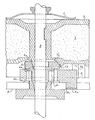
- the figure represents a part of a self-starting synchronous motor, comprising a stator part with two flanges and a coil, only one 8 of the two flanges being represented, and a rotor part.
- the rotor comprises a ferrite 1 molded in a support 3, for example made of plastic, preferably loaded with glass beads, integral in rotation, in a manner known per se, with the drive shaft 2 of the motor.
- the support 3 comprises, near one of its two orifices for the passage of the shaft 2, a frustoconical surface of the same axis as the shaft 2 and the support 3 of the motor.
- this frustoconical surface 3a is formed near the shaft 2, with an angle at the top of the relatively acute truncated cone, of the order of 40 °, and, on the right part of the figure, this frustoconical surface 3'a is distant from the shaft 2, with a more obtuse angle at the top, of the order of 90 °.
- the support 3 comprises, on the side of the same orifice for the passage of the shaft 2, a pinion with non-return toothing 3b, integral with this support.
- the support 3, the frustoconical surface 3a, 3'a and the non-return toothing 3b are obtained during the same molding operation.
- the motor comprises a second pinion 4, firstly mounted to rotate freely on the shaft 2, near the orifice for passage of the support 3 in question.
- This pinion 4 has a frustoconical surface corresponding to that of the support 3 and arranged to cooperate by friction therewith and thus be driven in rotation in the same direction as the rotor of the motor.
- the motor also comprises a non-return cam 5, provided with a light 5b, through which the shaft 2 extends and in which the pinion 4 projects, and a pivot pin 5a, mounted to rotate freely. in an orifice 8a formed in the flange 8 of the stator of the motor.
- the part of the pinion 4 projecting into the lumen of the cam 5 has a toothing 4b arranged to cooperate with a toothed sector, formed at the internal periphery of the lumen 5b of the cam 5, concentrically with its pivot axis 5a, so that , when the pinion 4 is driven in rotation by the rotor, it also drives the cam 5 in pivoting on its stud 5a, between two positions determined by the extent of the toothed sector 5b and, possibly, the two opposite bottoms of the light of drug.
- the cam 5 is also provided with a spout 5c, formed by the part of the cam disposed in line with the stud 5a, arranged to cooperate with the non-return toothing 3b of the support 3 and thus prevent the latter from turning in the wrong direction. meaning.
- an elastic washer 7 exerting a pressure force pressed on the support 3 of the rotor, on the side of its other orifice for passage of the shaft 2, for better driving or ensuring the support in friction cooperation with the pinion 4, by their respective frustoconical surfaces.
- the operation of the device is as follows. According to the direction of starting of the rotor 1, 2, 3, when the power is applied, the cam 5 is pivotally driven on its stud 5a by the pinion 4 in one direction or the other, via the surfaces frustoconical 3a, 4a or 3'a, 4'a in friction, one on the other, the spout 5c of the cam 5 cooperating or not with the non-return toothing 3b of the rotor. When the latter starts to turn in the wrong direction, the cam locks this toothing, and prevents the rotor from turning in this wrong direction.
- the drive of the pinion 4 by the rotor 1, 2, 3 is carried out by the frustoconical surfaces described above and the extent of which gives this drive excellent reliability.
Landscapes
- Physics & Mathematics (AREA)
- General Physics & Mathematics (AREA)
- Engineering & Computer Science (AREA)
- Power Engineering (AREA)
- Connection Of Motors, Electrical Generators, Mechanical Devices, And The Like (AREA)
Applications Claiming Priority (2)
| Application Number | Priority Date | Filing Date | Title |
|---|---|---|---|
| FR8002410A FR2475308A2 (fr) | 1980-02-04 | 1980-02-04 | Dispositif anti-retour pour petits moteurs synchrones |
| FR8002410 | 1980-02-04 |
Publications (2)
| Publication Number | Publication Date |
|---|---|
| EP0033693A1 EP0033693A1 (fr) | 1981-08-12 |
| EP0033693B1 true EP0033693B1 (fr) | 1984-04-25 |
Family
ID=9238192
Family Applications (1)
| Application Number | Title | Priority Date | Filing Date |
|---|---|---|---|
| EP81400137A Expired EP0033693B1 (fr) | 1980-02-04 | 1981-01-29 | Dispositif anti-retour pour moteur synchrone autodémarrant |
Country Status (4)
| Country | Link |
|---|---|
| EP (1) | EP0033693B1 (enExample) |
| DE (1) | DE3163252D1 (enExample) |
| ES (1) | ES499042A0 (enExample) |
| FR (1) | FR2475308A2 (enExample) |
Families Citing this family (1)
| Publication number | Priority date | Publication date | Assignee | Title |
|---|---|---|---|---|
| JPH06150236A (ja) * | 1992-10-30 | 1994-05-31 | Sankyo Seiki Mfg Co Ltd | 磁気ヘッド |
Citations (12)
| Publication number | Priority date | Publication date | Assignee | Title |
|---|---|---|---|---|
| GB800743A (en) * | 1955-12-16 | 1958-09-03 | Metamec Ltd | Improvements in or relating to means of controlling the direction of rotation of synchronous electric motors |
| US2972687A (en) * | 1957-01-14 | 1961-02-21 | Licentia Gmbh | Directional control for synchronous motors |
| FR1257684A (fr) * | 1959-03-27 | 1961-04-07 | Trilec | Moteur synchrone universel |
| US3111596A (en) * | 1959-09-22 | 1963-11-19 | Sangamo Electric Co | Synchronous electric motor |
| US3200915A (en) * | 1962-11-20 | 1965-08-17 | Gen Time Corp | No-back mechanism for small synchronous motors |
| FR90015E (fr) * | 1965-05-07 | 1967-09-29 | Crouzet Sa | Dispositif anti-retour silencieux pour petit moteur synchrone auto-démarreur |
| US3525888A (en) * | 1969-10-27 | 1970-08-25 | Mallory & Co Inc P R | Magnetic unidirectional system for a motor |
| FR2115597A6 (enExample) * | 1970-11-24 | 1972-07-07 | Crouzet Sa | |
| US3748508A (en) * | 1971-08-26 | 1973-07-24 | Scott & Fetzer Co | Motor constructions including a sliding stop member |
| FR2184170A5 (enExample) * | 1972-05-09 | 1973-12-21 | Crouzet Sa | |
| US3860841A (en) * | 1971-11-22 | 1975-01-14 | Crouzet Sa | Arrester device for small self-starting synchronous motors |
| FR2336823A1 (fr) * | 1975-12-24 | 1977-07-22 | Mallory & Co Inc P R | Dispositif de commande du sens de rotation d'un moteur synchrone |
Family Cites Families (4)
| Publication number | Priority date | Publication date | Assignee | Title |
|---|---|---|---|---|
| US3123192A (en) * | 1964-03-03 | Direction control means for bi-directional motors | ||
| BE657014A (enExample) * | 1963-12-13 | 1965-06-11 | ||
| NL6601500A (enExample) * | 1966-02-05 | 1967-08-07 | ||
| DE2362611A1 (de) * | 1973-12-17 | 1975-06-19 | Stegmann Uhren Elektro | Anlaufhilfe fuer synchronmotoren mit dauermagnetlaeufer |
-
1980
- 1980-02-04 FR FR8002410A patent/FR2475308A2/fr active Granted
-
1981
- 1981-01-29 DE DE8181400137T patent/DE3163252D1/de not_active Expired
- 1981-01-29 EP EP81400137A patent/EP0033693B1/fr not_active Expired
- 1981-02-02 ES ES499042A patent/ES499042A0/es active Granted
Patent Citations (12)
| Publication number | Priority date | Publication date | Assignee | Title |
|---|---|---|---|---|
| GB800743A (en) * | 1955-12-16 | 1958-09-03 | Metamec Ltd | Improvements in or relating to means of controlling the direction of rotation of synchronous electric motors |
| US2972687A (en) * | 1957-01-14 | 1961-02-21 | Licentia Gmbh | Directional control for synchronous motors |
| FR1257684A (fr) * | 1959-03-27 | 1961-04-07 | Trilec | Moteur synchrone universel |
| US3111596A (en) * | 1959-09-22 | 1963-11-19 | Sangamo Electric Co | Synchronous electric motor |
| US3200915A (en) * | 1962-11-20 | 1965-08-17 | Gen Time Corp | No-back mechanism for small synchronous motors |
| FR90015E (fr) * | 1965-05-07 | 1967-09-29 | Crouzet Sa | Dispositif anti-retour silencieux pour petit moteur synchrone auto-démarreur |
| US3525888A (en) * | 1969-10-27 | 1970-08-25 | Mallory & Co Inc P R | Magnetic unidirectional system for a motor |
| FR2115597A6 (enExample) * | 1970-11-24 | 1972-07-07 | Crouzet Sa | |
| US3748508A (en) * | 1971-08-26 | 1973-07-24 | Scott & Fetzer Co | Motor constructions including a sliding stop member |
| US3860841A (en) * | 1971-11-22 | 1975-01-14 | Crouzet Sa | Arrester device for small self-starting synchronous motors |
| FR2184170A5 (enExample) * | 1972-05-09 | 1973-12-21 | Crouzet Sa | |
| FR2336823A1 (fr) * | 1975-12-24 | 1977-07-22 | Mallory & Co Inc P R | Dispositif de commande du sens de rotation d'un moteur synchrone |
Also Published As
| Publication number | Publication date |
|---|---|
| ES8201367A1 (es) | 1981-12-16 |
| DE3163252D1 (en) | 1984-05-30 |
| ES499042A0 (es) | 1981-12-16 |
| FR2475308B2 (enExample) | 1983-12-23 |
| FR2475308A2 (fr) | 1981-08-07 |
| EP0033693A1 (fr) | 1981-08-12 |
Similar Documents
| Publication | Publication Date | Title |
|---|---|---|
| EP0121497B1 (fr) | Actuateur linéaire à moteur électrique | |
| FR2650636A1 (fr) | Ameliorations apportees aux pompes pour appareils electromenagers qui sont actionnees par un moteur synchrone | |
| EP0033693B1 (fr) | Dispositif anti-retour pour moteur synchrone autodémarrant | |
| EP0482443B1 (fr) | Dispositif de freinage d'une roue d'un engrenage | |
| FR2724430A1 (fr) | Dispositif de transmission a limitation de couple | |
| FR2571339A1 (fr) | Dispositif de commande d'un capuchon de fermeture d'un recipient de liquide | |
| EP0788950A1 (fr) | Dispositif d'essuie-glace, notamment pour un véhicule automobile, muni de moyens d'indexation de l'essuie-glace par rapport à un arbre d'entraînement | |
| EP0073692B1 (fr) | Dispositif d'entraînement par engrenage et son application à un lève-glace de véhicule automobile | |
| EP0008247B1 (fr) | Dispositif de lève-glace électrique | |
| FR2534724A1 (fr) | Mecanisme de liaison intermittente | |
| WO2002043927A1 (fr) | Cle dynamometrique | |
| EP0444372A1 (fr) | Moyen d'assemblage élastique de deux éléments oscillants et en particulier des lames d'un ciseau | |
| EP0337864A1 (fr) | Porte-monture de lunettes perfectionné pour machine à réproduire | |
| CH648974A5 (en) | Method for a centrally controlled telecommunication exchange system, particularly telephone exchange system, with a central control unit and peripheral control units | |
| EP0211704B1 (fr) | Rotor de distributeur d'allumage de moteur à combustion interne | |
| FR2622349A1 (fr) | Temporisateur a rearmement manuel | |
| EP0349368B1 (fr) | Frein à disque réglable | |
| FR2561739A1 (fr) | Dispositif d'entrainement, en particulier pour l'entrainement d'un mecanisme de commande | |
| FR2478240A1 (fr) | Perfectionnements aux entraineurs unidirectionnels a cliquets | |
| CH691748A5 (fr) | Entraînement du barillet d'un mouvement d'horlogerie automatique. | |
| EP0207833A1 (fr) | Bouton fileté à limiteur de couple | |
| JPS6136043Y2 (enExample) | ||
| EP0619071A1 (fr) | Moulinet de pêche à la mouche | |
| EP0363245B1 (fr) | Dispositif de réglage de la position angulaire d'un organe entraînant un arbre de commande rotatif | |
| FR2646008A1 (fr) | Potentiometre rotatif |
Legal Events
| Date | Code | Title | Description |
|---|---|---|---|
| PUAI | Public reference made under article 153(3) epc to a published international application that has entered the european phase |
Free format text: ORIGINAL CODE: 0009012 |
|
| AK | Designated contracting states |
Designated state(s): BE CH DE GB IT NL SE |
|
| 17P | Request for examination filed |
Effective date: 19811029 |
|
| ITF | It: translation for a ep patent filed | ||
| GRAA | (expected) grant |
Free format text: ORIGINAL CODE: 0009210 |
|
| AK | Designated contracting states |
Designated state(s): BE CH DE GB IT LI NL SE |
|
| REF | Corresponds to: |
Ref document number: 3163252 Country of ref document: DE Date of ref document: 19840530 |
|
| PLBE | No opposition filed within time limit |
Free format text: ORIGINAL CODE: 0009261 |
|
| STAA | Information on the status of an ep patent application or granted ep patent |
Free format text: STATUS: NO OPPOSITION FILED WITHIN TIME LIMIT |
|
| 26N | No opposition filed | ||
| PGFP | Annual fee paid to national office [announced via postgrant information from national office to epo] |
Ref country code: GB Payment date: 19901224 Year of fee payment: 11 |
|
| PGFP | Annual fee paid to national office [announced via postgrant information from national office to epo] |
Ref country code: CH Payment date: 19910114 Year of fee payment: 11 |
|
| PGFP | Annual fee paid to national office [announced via postgrant information from national office to epo] |
Ref country code: SE Payment date: 19910121 Year of fee payment: 11 |
|
| PGFP | Annual fee paid to national office [announced via postgrant information from national office to epo] |
Ref country code: DE Payment date: 19910126 Year of fee payment: 11 |
|
| ITTA | It: last paid annual fee | ||
| PGFP | Annual fee paid to national office [announced via postgrant information from national office to epo] |
Ref country code: NL Payment date: 19910131 Year of fee payment: 11 |
|
| PGFP | Annual fee paid to national office [announced via postgrant information from national office to epo] |
Ref country code: BE Payment date: 19910214 Year of fee payment: 11 |
|
| PG25 | Lapsed in a contracting state [announced via postgrant information from national office to epo] |
Ref country code: GB Effective date: 19920129 |
|
| PG25 | Lapsed in a contracting state [announced via postgrant information from national office to epo] |
Ref country code: SE Effective date: 19920130 |
|
| PG25 | Lapsed in a contracting state [announced via postgrant information from national office to epo] |
Ref country code: LI Effective date: 19920131 Ref country code: CH Effective date: 19920131 Ref country code: BE Effective date: 19920131 |
|
| BERE | Be: lapsed |
Owner name: CROUZET Effective date: 19920131 |
|
| PG25 | Lapsed in a contracting state [announced via postgrant information from national office to epo] |
Ref country code: NL Effective date: 19920801 |
|
| NLV4 | Nl: lapsed or anulled due to non-payment of the annual fee | ||
| GBPC | Gb: european patent ceased through non-payment of renewal fee | ||
| REG | Reference to a national code |
Ref country code: CH Ref legal event code: PL |
|
| PG25 | Lapsed in a contracting state [announced via postgrant information from national office to epo] |
Ref country code: DE Effective date: 19921001 |
|
| EUG | Se: european patent has lapsed |
Ref document number: 81400137.6 Effective date: 19920806 |