EP0032829A2 - Appareil de filtrage de liquide - Google Patents
Appareil de filtrage de liquide Download PDFInfo
- Publication number
- EP0032829A2 EP0032829A2 EP81300206A EP81300206A EP0032829A2 EP 0032829 A2 EP0032829 A2 EP 0032829A2 EP 81300206 A EP81300206 A EP 81300206A EP 81300206 A EP81300206 A EP 81300206A EP 0032829 A2 EP0032829 A2 EP 0032829A2
- Authority
- EP
- European Patent Office
- Prior art keywords
- media
- filter
- roller
- plates
- filter media
- Prior art date
- Legal status (The legal status is an assumption and is not a legal conclusion. Google has not performed a legal analysis and makes no representation as to the accuracy of the status listed.)
- Granted
Links
Images

Classifications
-
- B—PERFORMING OPERATIONS; TRANSPORTING
- B01—PHYSICAL OR CHEMICAL PROCESSES OR APPARATUS IN GENERAL
- B01D—SEPARATION
- B01D25/00—Filters formed by clamping together several filtering elements or parts of such elements
- B01D25/12—Filter presses, i.e. of the plate or plate and frame type
- B01D25/127—Filter presses, i.e. of the plate or plate and frame type with one or more movable filter bands arranged to be clamped between the press plates or between a plate and a frame during filtration, e.g. zigzag endless filter bands
- B01D25/1275—Filter presses, i.e. of the plate or plate and frame type with one or more movable filter bands arranged to be clamped between the press plates or between a plate and a frame during filtration, e.g. zigzag endless filter bands the plates or the frames being placed in a non-vertical position
Definitions
- This invention relates to liquid filtering apparatus of the separable plate type and more particularly, it relates to such a filtering apparatus in combination with a mechanism for supplying fresh filter media to, and removing used filter media from, the filtering apparatus.
- a liquid filtering device comprising a plurality of filter plates which, when placed together, form liquid containers, means for moving said plates together for retaining elongated sheets of flexible filter media between adjacent plates, thereby forming a pair of fluid-tight chambers on opposite sides of each sheet, there being an inlet to one chamber and an outlet to the opposite chamber on the other side of the sheet, and means for separating the plates when the sheets of filter media are contaminated, and a sheet extraction and advancing means for the various sheets of filter media adjacent the filtering device comprising: an elongated drive roller for each sheet of filter media supported by a frame and extending generally perpendicular to the longitudinal centre line of the media and controllable power means for rotating each said drive roller being a plurality of rotatable pinch wheels mounted
- a filtering apparatus wherein a series of horizontal plates are arranged in a stacked arrangement to form a series of inlet chambers for dirty liquid to be filtered.
- the plates are separable to an open position to allow the placement of a sheet of filter media between them and when closed, they are sealed against the media around their edges to form an inlet chamber for each plate on one side of the media and, under a suitable grill, a collection chamber for clean, filtered liquid on the opposite side of the media.
- the inlet chambers are each connected to an inlet conduit for dirty liquid and the collection chambers are connected in parallel to a common conduit for clean filtrate.
- filter media in the form of filter paper supplied from rolls located adjacent one side of the filter plates is pulled between the plates by a media pulling apparatus adjacent the other side of the plates.
- the pulling apparatus includes a mechanism for inserting pins into the filter media to move it for a sufficient distance so that used filter media is completely removed from between each adjacent pair of separated filter plates and is replaced by fresh media before the plates are again closed.
- additional filter media such as diatomaceous earth
- the paper type filter media may be pulled, using a crown roller in combination with a pinch roller, connected to a driving mechanism.
- crown roll so as to be driven satisfactorily and in many instances the media would track off to one side of the crown roll and prevent proper sealing of the media by the closing plates.
- Such erratic operation required continuous surveilance and frequent manual adjustments and thus prevented the filter from being operated automatically and unattended for long periods of time.
- a liquid filtering device comprising a plurality of filter plates which, when placed together, form liquid containers, means for moving said plates together for retaining elongated sheets of flexible filter media between adjacent plates, thereby forming a pair of fluid-tight chambers on opposite sides of each sheet, therebeing an inlet to one chamber and an outlet to the opposite chamber on the other side of the sheet, and means for separating the plates when the sheets of filter media are contaminated, and a sheet extraction and advancing means for the various sheets of filter media adjacent the filtering device comprising: an elongated drive roller for each sheet of filter media supported by a frame and extending generally perpendicular to the longitudinal centre of the media and controllable power means for rotating each said drive roller; wherein a bar is located adjacent each said drive roller, there being a plurality of rotatable pinch wheels mounted on said bar, at least said pinch wheels being freely rotatable, there being means for urging each said bar towards its adjacent roller so that said pinch wheels will press against the filter media which is partially
- each said pinch wheels are circular discs with a central hub portion that are axially adjustable on said bar, each said disc having a tapered peripheral edge for penetrating accumulated filter cake on the media.
- each said drive roller may have a knurled outer surface.
- the filter media moving device of a filter in accordance with the invention that can accommodate plain sheet type media or media with a relatively thick filter cake.
- Each sheet of filter media is a driven roller whose longitudinal axis is generally perpendicular to the direction of travel of the filter media and the center line of the plates.
- a rotatable pinch means is provided which is also movable against the crown roller to engage the sheet media and cause it to press together against the drive roller even though the media may have on it a relatively thick layer of filter cake plus accumulated or filtered-out material.
- the rotatable pinch means has a series of spaced apart disc-like members or pinch wheels, which can cut through the filter cake to press the sheet media against the drive roller to provide a firm, non-slipping driving contact, thereby enabling the drive roller, which is rotated by an appropriate power means, to pull and advance the media, removing used media from between separated filter plates and moving new media into place.
- the drive roller may be mounted so that its longitudinal axis can be adjusted angularly relative to its nominal position and this movement may be controlled automatically to assure tracking of the new paper media between the filter plates as it is moved into position.
- a filter device in accordance with the invention may include a fixed bearing means for supporting one end of each said drive roller and a movable bearing means for supporting the other end of said roller; and means for adjusting the position of said movable bearing means in order to vary the angular position of the roller axis relative to the fixed orientation of said adjacent filter plates to thereby keep the filter media centered on said roller and between the filter plates as it is advanced by said power means.
- Said means for adjusting the position of said movable bearing means may comprise a media alignment sensing means for providing signals when the media travel varies from a preselected path; linear actuator means connected to said movable bearing means; and means for operating said actuator means in response to signals provided by said media alignment sensing means.
- Said movable bearing means comprises a movable mounting plate on one side of said frame, a self-aligning bearing fixed to said mounting plate, said actuator means having a movable arm connected to such mounting plate.
- Said movable bearing means may comprise a slot for retaining one end of said pinch wheel bar.
- said means for urging said bar towards its adjacent roller comprises a linearly movable member engaging said bar and connected by linkage means fixed to said bearing plate and to a manually controllable handle.
- Said fixed bearing means may include a bearing plate similar to said movable bearing plate but retained in a fixed position on said frame.
- filter media supply means is provided adjacent the opposite ends - of said plurality of filter plates, said supply means comprising: a support frame having vertical frame members, fixed horizontal members on one side and removable horizontal members on its other side; a series of elongated supply roll support members fixed at one end to said fixed horizontal members of said frame and supported at their other ends by said removable horizontal members; adjustable means on each roll support member for supporting a roll of filter media in proper alignment with said filter plates.
- Said adjustable means may comprise a pair of annular retaining rings with means for attaching them at a fixed location along a said support member, and a conical collar adjacent each said retaining ring for supporting a roll of filter media.
- rolls of paper media for the various pairs of plates are supported so as to be readily replaceable when required. Also, each roll is supported between self- adjusting bearing supports so that, once initially positioned, the paper media will continue to track in the proper direction of travel, relative to its pair of filter plates, when advanced.
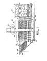
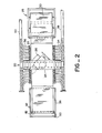
- Figures 1 and 2 show a filter apparatus 20 utilizing a filter media control mechanism in accordance with the present invention.
- the filter comprises a stack of horizontal plates 22 supported by a frame 24 and controlled by a mechanism including a power jack 26 for separating and closing the plates.
- a supply rack 28 On one side of the plates is a supply rack 28 for a series of rolls 30 of filter media and on the opposite side of the plates is an extractor mechanism 32 for removing used filter media and placing new media into position between plates.
- the filter media may be a suitable paper, of a type well known in the art, and a sheet from each supply roll extends between one pair of adjacent plates to the extractor mechanism.
- inlet and outlet chambers are formed by the plates on opposite sides of the filter sheet so that dirty liquid fills the top or inlet chamber and clean filtrate collects in the bottom or outlet chamber.
- Details of the filter plates are not shown herein, since the plates are conventional, but plates for a typical filter of this type are shown in U.S.A. Patent Specification No.3,608,734.
- Suitable conduits or hoses 34 and 36, to and from each of these inlet and outlet chambers are connected to common or main inlet and outlet pipes 38 and 40, for the dirty liquid and the clean filtrate on opposite sides of the filter.
- the extractor mechanism 32 comprises a series of drive rollers 42, one for each continuous sheet of filter media, extending between a particular pair of filter plates and from one of the supply rolls 30.
- drive rollers are supported by a frame which, in the embodiment shown in Figures 1 and 2, is made up of pairs of spaced apart horizontal members 44 connected at their outer ends by diagonal members 46 which slope downwardly toward the base support 48 for the filter plates and by cross-connecting members 50.
- each drive roller 42 is generally an elongated cylinder whose diameter is preferably somewhat larger at its centre and decreases slightly and symmetrically from this centre to its opposite ends.
- each roller 42 has a convex curved surface, or a straight taper, between its ends and may be referred to as a crown roller.
- each crown roller has a knurled or irregular surface that provides increased friction with the paper media wrapped around it and extending from its opposite ends are axles or shafts 52 which are supported in a pair of bearings on the extractor. At one end the axle 52 extends beyond its bearing and has a fixed sprocket 54 attached thereto which is driven by chain 56 from a suitable controllable power drive unit (not shown). All of the rollers are similarly connected to the chain so that they may be driven simultaneously by the power unit.
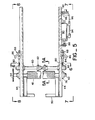
- a single extractor for one drive roller is shown somewhat schematically in Figure 3 in order to illustrate certain features of the invention.
- a sheet of the filter media 30 from a supply roll extending between a pair of plates 22 and partially wrapped around the crown roller 42 and then up and partially around a pinch wheel device.
- this pinch wheel device 58 comprises an elongated bar 60 to which is attached a series of adjustable disc-like pinch wheels 62 of equal diameter.
- the number of pinch wheels may vary but for a crown roll of around 1.22 metres (4 feet) in length, four to six such pinch wheels are generally sufficient.
- Each pinch wheel has a relatively thick central hub por.tion 64 with a hole that forms a slidable fit with the bar so that the pinch wheel can be moved to any desired position along the bar and then be retained by a set screw (not shown).
- each pinch wheel tapers radially outwardly from its hub portion to a relatively narrow (e.g.l.5 to 2.5 mm (0.06 to 0.10 inches)) outer edge 66.
- a sheet of used filter media is being removed from the filter plates, and it has a layer or cake of collected filter material and dirt thereon, with a thickness of from 12 to 26 mm, (0.5 to 1.0 inches)
- the pinch wheels will cut through the cake to press the paper media firmly against the crown roller as they and the bar rotate freely.
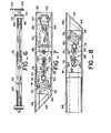
- the pinch bar and thus the pinch wheels 623 are movable from a retracted, deactivated position, as shown in Figures 4 and 4A, to an engaged, operative position against the crown roller, as shown in Figures 5 and 5A.
- This movement from the deactivated position to the operative position may be accomplished by manually operated, two-position actuators 68 located at opposite ends of the pinch wheel bar, preferably of a type that is self latching in both positions.
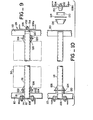
- Both the drive (or crown) roll 42 and its pinch wheel bar 60 for each sheet of filter media are supported at each end by a single rectangular bearing plate 70.
- the pair of bearing plates 70 are mounted on two opposed horizontal frame members 44 of the extractor 32, which comprise a pair of frame members. On both sides of the extractor, as shown in Figures 7 and 8, each bearing plate 70 may be mounted so as to be movable for adjusting the position of the associated crown roll 42, as described below.
- Each plate itself is provided with four slots 72 near its corners and extending through each slot is a bolt or pin 74 fixed to the adjacent horizontal member of the extractor frame.
- a flanged bearing assembly 76 for the end shaft 52 of the crown roll 42 is fixed to each plate 70 and adjacent thereto is a larger horizontally extending slot 78 for supporting one end of the pinch wheel bar 60.
- An end portion of this latter bar that extends beyond the slot is fixed to the threaded end of a movable rod 80 which is part of a two-positioned actuator 68 that is also fixed to the bearing plate 70.
- a pair of nuts 82 are provided on the threaded portion of the rod so that the positions of the pinch wheel shaft or bar 60 relative to the adjacent crown roll 42, when the rod is fully extended, can be adjusted.
- the rod 80 is connected to an intermediate link 84 that is also fixed to a handle 86.
- the handle in one position (when the filter media paper is being moved while the filter is not in operation or when the paper is held stationary during normal filter operations) the handle is as shown in the position of Figure 5.
- the handle for the pinch wheel shaft is as shown in Figure 4 with the pinch wheels separated from the crown roll so that the fresh media can be threaded between them.
- each sheet of paper media when initially centered properly on its crown roller, will remain centered as the crown roller rotates to remove used media and pull new media into position between the filter plates.
- an automatic paper centering system is used.
- each crown roller is adjustably mounted on their horizontal extractor frame members 44 but the bearing plates on one side of the extractor may also be separately movable in order to change the angular position of the crown roll relative to the horizontal central axis of the filter plates, if such a change is necessary to keep the filter media properly centered on the crown roll.
- a controllable actuator 90 such as a pneumatic cylinder.
- this cylinder is mounted on a plate 92 fixed to the horizontal frame members.
- Tubing connections 94 and 96 to opposite ends of the cylinder extend from a four-way solenoid valve 98, also fixed to the plate 92. As shown somewhat schematically in Figure 3, this valve is connected to a suitable power source for the cylinder and it is controlled by signals from a sensor 100 on the extractor frame. Such signals are generated if, and -when, the paper media tends to move from its proper direction of travel with respect to the crown roll.
- the sensor may be of a type that is commercially available, such as the type comprising essentially a pair of jaws between which the edge of the paper travels.
- a light source provided in one jaw section is aligned with a photocell in the opposite jaw and the sensor is positioned on the extractor so that deviation of the edge of the moving paper media from its normal path will interrupt the light directed to the photocell.
- the sensor 100 is not activated, but if for some reason the paper media starts to veer off course and moves further between its jaws so that the energy or light flowing to the sensor cell is interrupted, a signal is furnished to the photocell control unit 102 which is provided with power from a suitable source via a supply lead 104.
- the control unit then supplies a signal to the solenoid operated air valve 98 connected to a compressed air source (not shown) and having the two air lines 94 and 96 connected to opposite ends of the double acting, pneumatic actuator 90.
- the rolls of filter media 30 are supported by the supply rack 28 in a manner that helps to maintain proper media alignment with the filter plates.
- the rack is comprised of horizontal frame members 108 that are fixed at their ends to vertical frame members 110.
- horizontal frame members are permanently attached to the vertical members and on the other side they are removable to allow replacement of a filter media roll.
- One end of a cylindrical roller 116 fits within each collar and is secured thereto by suitable means, such as a circular weldment 118 so that it is cantilevered toward the other side of the rack.
- each roller On the inner end of each roller is an adjustable, annular retainer collar 120 with a set screw 122 to hold it in place, a washer 124 and a conical collar 126 that tapers to the surface of the roller.
- a similar conical collar, washer and adjustable retainer collar At the outer end of the roller is a similar conical collar, washer and adjustable retainer collar.
- the removable horizontal frame member 108a which is attached by removable fasteners (not shown) to the frame members, is provided with spaced apart holes 128 in order to support the rollers 116 extending from the opposite, fixed horizontal member.
- a frusto-conical plug 130 is provided for each roller and has a threaded stud portion 132 that extends through a hole.
- This plug fits within the free end of a roller to provide support and is retained by a nut 134 threaded to the stud portion on the opposite side of the horizontal member.
- the procedure is simple and straightforward.
- the appropriate horizontal member 108a is first removed, at least at one end, so that it can be moved out of the way.
- the outer washer 124, cone 126, and collars 120 are also removed.
- a paper media roll can. then be placed on a cantilevered roller 116 with both inner and outer tapered collars 126 adjusted to the proper position to align the paper media accurately with the filter plates.
- the outer washer 124 and collar 120 are then placed on the roller and the horizontal member is attached and bolted into place after the plug 130 is placed within the open end of the roller.
- the above described plate type filter has an efficient, but relatively simple, filter media handling system.
- the system will operate reliably even though the sheet- type filter media has a substantial layer or cake of filter aid or dirt because the pinch wheels can penetrate the cake and provide the necessary friction on the driving crown roller.
- the crown roller will normally maintain the media on its proper alignment relative to the filter papers, aided in part by the self-sdjusting manner in which the supply rolls are supported. If, for some reason, the media may tend to veer to-one side during a retraction cycle, the position of the crown roller will be automatically adjusted by the sensor/actuator system to move back into proper alignment.
- the above described plate type filtering apparatus has filter media handling system that will operate efficiently even when the sheet type media has accumulated a relatively thick layer of filter aid cake and dirt.
- the filter media extractor uses a drive roller in combination with a series of pinch wheels or discs that penetrate the layer or cake of filter aid on the media and provide the necessary friction to enable the crown roller to extract the old media and replace it with new media from the supply rolls.
- the described media supply and extraction system is automatically adjustable to maintain proper alignment with the filter when being moved, and is easy to service and maintain with relatively unskilled labour. Also, in the described device a plurality of supply rolls of filter media for a plate type filter are supported so that the media can be easily aligned with its extractor roll and maintain proper tracking between adjacent filter plates.
Landscapes
- Chemical & Material Sciences (AREA)
- Chemical Kinetics & Catalysis (AREA)
- Filtration Of Liquid (AREA)
Applications Claiming Priority (2)
| Application Number | Priority Date | Filing Date | Title |
|---|---|---|---|
| US06/113,187 US4289615A (en) | 1980-01-18 | 1980-01-18 | Filter media mover for plate type filter |
| US113187 | 2002-04-01 |
Publications (3)
| Publication Number | Publication Date |
|---|---|
| EP0032829A2 true EP0032829A2 (fr) | 1981-07-29 |
| EP0032829A3 EP0032829A3 (en) | 1982-03-10 |
| EP0032829B1 EP0032829B1 (fr) | 1985-03-20 |
Family
ID=22348040
Family Applications (1)
| Application Number | Title | Priority Date | Filing Date |
|---|---|---|---|
| EP81300206A Expired EP0032829B1 (fr) | 1980-01-18 | 1981-01-16 | Appareil de filtrage de liquide |
Country Status (5)
| Country | Link |
|---|---|
| US (1) | US4289615A (fr) |
| EP (1) | EP0032829B1 (fr) |
| JP (1) | JPS56115607A (fr) |
| CA (1) | CA1141675A (fr) |
| DE (1) | DE3169314D1 (fr) |
Cited By (3)
| Publication number | Priority date | Publication date | Assignee | Title |
|---|---|---|---|---|
| US4869834A (en) * | 1987-08-05 | 1989-09-26 | Tenag Ag | Method and apparatus for controlling run of a moving web in a predetermined path, especially a filter material web, through a plate filter |
| US5338443A (en) * | 1992-06-29 | 1994-08-16 | Henry Filters, Inc. | Filter media tensioning device |
| US5420708A (en) * | 1990-08-31 | 1995-05-30 | Idemitsu Kosan Co., Ltd. | Color filters, including taking out electrodes or post-ito layer |
Families Citing this family (9)
| Publication number | Priority date | Publication date | Assignee | Title |
|---|---|---|---|---|
| JPS5910313A (ja) * | 1982-07-08 | 1984-01-19 | Mitsubishi Kakoki Kaisha Ltd | 「ろ」紙の引出し装置 |
| US4477350A (en) * | 1983-03-14 | 1984-10-16 | Brandt & Associates, Inc. | Liquid filtering apparatus |
| US4738775A (en) * | 1986-09-15 | 1988-04-19 | Schnieder John R | Paper extractor for plate filter |
| US5258119A (en) * | 1991-06-17 | 1993-11-02 | Womack International, Inc. | Filter assembly with filter media retrieval |
| US5238584A (en) * | 1992-01-28 | 1993-08-24 | J. R. Schneider Co., Inc. | Apparatus for removing filtrate from filter media |
| US5292434A (en) * | 1992-04-07 | 1994-03-08 | Benesi Steve C | Filter apparatus and method using belt filter medium |
| US5449455A (en) * | 1992-05-18 | 1995-09-12 | Womack International, Inc. | Closer mechanism for compact filter press assembly and method of operation |
| WO2013142764A2 (fr) | 2012-03-22 | 2013-09-26 | E. I. Du Pont De Nemours And Company | Traitement d'eau produite en récupération d'huile |
| US9284830B2 (en) | 2012-03-22 | 2016-03-15 | E I Du Pont De Nemours And Company | Method for recovering hydrocarbon fluids using a hydraulic fracturing process |
Family Cites Families (10)
| Publication number | Priority date | Publication date | Assignee | Title |
|---|---|---|---|---|
| US1602829A (en) * | 1925-01-19 | 1926-10-12 | Jasper A Mccaskell | Scraping device |
| US1797248A (en) * | 1927-07-20 | 1931-03-24 | American Anode Inc | Filtering method and apparatus |
| DE920009C (de) * | 1939-06-03 | 1954-11-11 | Gustav Netzel Dipl Ing | Verfahren und Vorrichtung zur Abnahme des Filterkuchens von Drehfiltern |
| DE922705C (de) * | 1939-06-03 | 1955-01-24 | Gustav Dipl-Ing Netzel | Abnahmevorrichtung fuer Filterkuchen von Drehfiltern |
| US2439251A (en) * | 1946-03-02 | 1948-04-06 | Beloit Iron Works | Band guide |
| DE900297C (de) * | 1950-11-07 | 1953-12-21 | Heinz Hoening Dipl Volksw | Pressvorrichtung fuer fluessigkeitshaltige Faservliese, insbesondere zur Zellstoffentwaesserung |
| US2867326A (en) * | 1955-09-27 | 1959-01-06 | Hirs Gene | Filter apparatus |
| US2867325A (en) * | 1955-09-27 | 1959-01-06 | Hirs Gene | Filter apparatus |
| US3608734A (en) * | 1968-07-31 | 1971-09-28 | John R Schneider | Liquid filtering apparatus |
| DE2227356C3 (de) * | 1972-06-06 | 1975-10-09 | Kuesters, Eduard, 4150 Krefeld | Verfahren zur Herstellung einer Rillenwalze |
-
1980
- 1980-01-18 US US06/113,187 patent/US4289615A/en not_active Expired - Lifetime
- 1980-12-17 CA CA000367039A patent/CA1141675A/fr not_active Expired
-
1981
- 1981-01-16 DE DE8181300206T patent/DE3169314D1/de not_active Expired
- 1981-01-16 EP EP81300206A patent/EP0032829B1/fr not_active Expired
- 1981-01-17 JP JP463081A patent/JPS56115607A/ja active Granted
Cited By (3)
| Publication number | Priority date | Publication date | Assignee | Title |
|---|---|---|---|---|
| US4869834A (en) * | 1987-08-05 | 1989-09-26 | Tenag Ag | Method and apparatus for controlling run of a moving web in a predetermined path, especially a filter material web, through a plate filter |
| US5420708A (en) * | 1990-08-31 | 1995-05-30 | Idemitsu Kosan Co., Ltd. | Color filters, including taking out electrodes or post-ito layer |
| US5338443A (en) * | 1992-06-29 | 1994-08-16 | Henry Filters, Inc. | Filter media tensioning device |
Also Published As
| Publication number | Publication date |
|---|---|
| CA1141675A (fr) | 1983-02-22 |
| EP0032829B1 (fr) | 1985-03-20 |
| US4289615A (en) | 1981-09-15 |
| JPS56115607A (en) | 1981-09-10 |
| JPH0260365B2 (fr) | 1990-12-17 |
| EP0032829A3 (en) | 1982-03-10 |
| DE3169314D1 (en) | 1985-04-25 |
Similar Documents
| Publication | Publication Date | Title |
|---|---|---|
| EP0032829B1 (fr) | Appareil de filtrage de liquide | |
| DE3888848T2 (de) | Reifenprüfungsmaschine mit einstellbarer wulstbreite. | |
| US5618424A (en) | Rotary drum type device for separating solid particles from a liquid | |
| US3608734A (en) | Liquid filtering apparatus | |
| WO1982003845A1 (fr) | Dispositif de decoupage et d'enroulement de bande a largeur variable | |
| DE3128587C2 (de) | Wellpappenmaschine zur Herstellung einseitiger Wellpappe | |
| EP0919499B1 (fr) | Dispositif d'enroulement pour placage | |
| JPH0859001A (ja) | 印刷媒体を供給する方法と装置 | |
| US5112485A (en) | Drum filter | |
| CN116022585A (zh) | 一种用于纸卷加工的复卷机 | |
| EP1305156B1 (fr) | Appareil de remise a neuf de courroies | |
| CA1054340A (fr) | Regulateur de debit de solides | |
| US4336139A (en) | Vacuum pan raising and lowering system | |
| US5076092A (en) | Yieldable roller assembly for a die set in a stamping press | |
| CA2088213C (fr) | Appareil pour enlever le filtrat contenu dans un milieu filtrant | |
| CN114474692A (zh) | 一种具有夹持功能的超滤膜生产用拉伸装置 | |
| KR100794748B1 (ko) | 백업롤 세퍼레터 분해조립장치 | |
| CN219745517U (zh) | 一种饲料生产用初清筛 | |
| CN221234854U (zh) | 过滤膜放卷调节装置 | |
| CN223221068U (zh) | 纤连蛋白提纯装置 | |
| CN216609210U (zh) | 拖布机 | |
| CN212953213U (zh) | 一种电气自动化送料装置 | |
| CN112520130B (zh) | 陶瓷膜生产系统 | |
| JPS6346085Y2 (fr) | ||
| JPH0439222Y2 (fr) |
Legal Events
| Date | Code | Title | Description |
|---|---|---|---|
| PUAI | Public reference made under article 153(3) epc to a published international application that has entered the european phase |
Free format text: ORIGINAL CODE: 0009012 |
|
| AK | Designated contracting states |
Designated state(s): CH DE FR GB IT |
|
| PUAL | Search report despatched |
Free format text: ORIGINAL CODE: 0009013 |
|
| AK | Designated contracting states |
Designated state(s): CH DE FR GB IT |
|
| RHK1 | Main classification (correction) |
Ipc: B01D 29/02 |
|
| 17P | Request for examination filed |
Effective date: 19811005 |
|
| ITF | It: translation for a ep patent filed | ||
| GRAA | (expected) grant |
Free format text: ORIGINAL CODE: 0009210 |
|
| AK | Designated contracting states |
Designated state(s): CH DE FR GB IT LI |
|
| REF | Corresponds to: |
Ref document number: 3169314 Country of ref document: DE Date of ref document: 19850425 |
|
| ET | Fr: translation filed | ||
| PLBE | No opposition filed within time limit |
Free format text: ORIGINAL CODE: 0009261 |
|
| STAA | Information on the status of an ep patent application or granted ep patent |
Free format text: STATUS: NO OPPOSITION FILED WITHIN TIME LIMIT |
|
| 26N | No opposition filed | ||
| PGFP | Annual fee paid to national office [announced via postgrant information from national office to epo] |
Ref country code: FR Payment date: 19900115 Year of fee payment: 10 |
|
| PGFP | Annual fee paid to national office [announced via postgrant information from national office to epo] |
Ref country code: CH Payment date: 19900130 Year of fee payment: 10 |
|
| ITTA | It: last paid annual fee | ||
| PGFP | Annual fee paid to national office [announced via postgrant information from national office to epo] |
Ref country code: GB Payment date: 19900131 Year of fee payment: 10 |
|
| PGFP | Annual fee paid to national office [announced via postgrant information from national office to epo] |
Ref country code: DE Payment date: 19900228 Year of fee payment: 10 |
|
| PG25 | Lapsed in a contracting state [announced via postgrant information from national office to epo] |
Ref country code: GB Effective date: 19910116 |
|
| PG25 | Lapsed in a contracting state [announced via postgrant information from national office to epo] |
Ref country code: LI Effective date: 19910131 Ref country code: CH Effective date: 19910131 |
|
| GBPC | Gb: european patent ceased through non-payment of renewal fee | ||
| PG25 | Lapsed in a contracting state [announced via postgrant information from national office to epo] |
Ref country code: FR Effective date: 19910930 |
|
| REG | Reference to a national code |
Ref country code: CH Ref legal event code: PL |
|
| PG25 | Lapsed in a contracting state [announced via postgrant information from national office to epo] |
Ref country code: DE Effective date: 19911001 |
|
| REG | Reference to a national code |
Ref country code: FR Ref legal event code: ST |