EP0032648B1 - Statische Penetrometervorrichtung - Google Patents
Statische Penetrometervorrichtung Download PDFInfo
- Publication number
- EP0032648B1 EP0032648B1 EP80420145A EP80420145A EP0032648B1 EP 0032648 B1 EP0032648 B1 EP 0032648B1 EP 80420145 A EP80420145 A EP 80420145A EP 80420145 A EP80420145 A EP 80420145A EP 0032648 B1 EP0032648 B1 EP 0032648B1
- Authority
- EP
- European Patent Office
- Prior art keywords
- rod
- ground
- pressure
- jack
- static penetrometer
- Prior art date
- Legal status (The legal status is an assumption and is not a legal conclusion. Google has not performed a legal analysis and makes no representation as to the accuracy of the status listed.)
- Expired
Links
Images

Classifications
-
- G—PHYSICS
- G01—MEASURING; TESTING
- G01N—INVESTIGATING OR ANALYSING MATERIALS BY DETERMINING THEIR CHEMICAL OR PHYSICAL PROPERTIES
- G01N3/00—Investigating strength properties of solid materials by application of mechanical stress
- G01N3/40—Investigating hardness or rebound hardness
-
- E—FIXED CONSTRUCTIONS
- E02—HYDRAULIC ENGINEERING; FOUNDATIONS; SOIL SHIFTING
- E02D—FOUNDATIONS; EXCAVATIONS; EMBANKMENTS; UNDERGROUND OR UNDERWATER STRUCTURES
- E02D1/00—Investigation of foundation soil in situ
- E02D1/02—Investigation of foundation soil in situ before construction work
- E02D1/022—Investigation of foundation soil in situ before construction work by investigating mechanical properties of the soil
-
- G—PHYSICS
- G01—MEASURING; TESTING
- G01N—INVESTIGATING OR ANALYSING MATERIALS BY DETERMINING THEIR CHEMICAL OR PHYSICAL PROPERTIES
- G01N2203/00—Investigating strength properties of solid materials by application of mechanical stress
- G01N2203/0001—Type of application of the stress
- G01N2203/0012—Constant speed test
-
- G—PHYSICS
- G01—MEASURING; TESTING
- G01N—INVESTIGATING OR ANALYSING MATERIALS BY DETERMINING THEIR CHEMICAL OR PHYSICAL PROPERTIES
- G01N2203/00—Investigating strength properties of solid materials by application of mechanical stress
- G01N2203/0058—Kind of property studied
- G01N2203/0076—Hardness, compressibility or resistance to crushing
Definitions
- the present invention relates to a static penetrometer, of the type comprising an element lowered into the ground and serving as a housing for a cylinder of substantially horizontal axis, the piston of which, subjected on at least one of its faces to the pressure of a fluid hydraulic or pneumatic, is integral with a rod capable of being inserted laterally into the ground or retracted inside the above-mentioned element, means being provided for locating the position of said rod and measuring the pressure exerted on it , said element being integral with the lower end of a drill string for lowering said element into the ground, this element also being connected to hydraulic or pneumatic fluid pipes as well as to other connecting lines.
- Such an apparatus makes it possible to carry out penetration tests for the recognition of soils and, more particularly for the "in situ” measurement of the static resistance of soils.
- the penetration test a means of recognizing commonly used soils, usually consists of sinking into the ground, from top to bottom, a probe placed at the lower end of a train of tubes or rods.
- This sinking can be carried out: either by threshing, by means of a sheep which strikes an anvil secured to the top of the train of tubes or rods, the device then being called “dynamic penetrometer”; either by slow speed actuation, in which case it is a "static penetrometer”.
- the present invention aims to remedy these drawbacks; its purpose is therefore to provide a device which can be directly dark in the ground, without prior drilling, ensuring perfect protection of the fluid pipes and other connections existing between the device and the surface, and providing a maximum stroke of the rod pressed laterally into the ground while ensuring adequate reaction to the penetration of this rod.
- the element serving as housing for the above-mentioned jack is a cylindro-conical point capable of being dark in the ground, the force of reaction to the insertion of the rod the ground being provided by the lateral contact of this cylindrical-conical point on the ground, and the rods of said string of rods are constituted by tubes enclosing the fluid tubes and the other connecting lines.
- the static penetration test is carried out along a horizontal axis, at any desired depth, by means of a preferably double-acting cylinder, housed inside a cylindro-conical point, of large diameter in its cylindrical part, dark point in the ground via the train of tubes which also has the function of ensuring the protection of the hydraulic or pneumatic fluid pipes as well as the electrical connections.
- the force of reaction to the penetration of the rod is provided by the lateral contact on the ground of the dark element and can be very much greater than the penetration force, taking into account the ratio of the surfaces of the rod and of the dark element.
- the rod can thus be introduced into the ground under a known pressure, then retracted at the end of the test into its housing, so as to continue the vertical sinking of the element which contains it, before carrying out a new test at another depth.
- the device thus allows, by pressure and displacement measurements, to know the resistance to static penetration of the soil, the interpretation of the test being the same as for a conventional static penetration test, the only difference being that the measurement is made along an axis horizontal; reading the pressure at the various stages of sinking the rod allows the resistance of the soil to be measured at a given depth.
- the invention gives rise to various embodiments, according to the means provided for moving the rod, in the direction of its insertion into the ground and of its retraction, and for measuring pressures and displacements.
- the pressure on the piston of the cylinder of horizontal axis is exerted, at least in the direction of the insertion of the rod into the ground, by means of a hydraulic fluid pressurized by a compressed gas supplied by a gas source, means being provided for measuring the pressure and the volume thereof, in order to know the resistance of the soil and to identify the position of the rod.
- the cylinder can be double-acting, in which case it is the aforementioned gas which, acting directly on the other face of the piston, makes it possible to retract the rod.
- the return force can be provided by a helical spring.
- two flexible tubes or only one, provide the connection between the apparatus located in the open air and the element lowered into the ground which contains the cylinder with a horizontal axis.
- the flexible tubing which encloses the hydraulic fluid is surrounded by a coaxial tubing, containing gas, in order to cancel the parasitic expansions of the interior tubing.
- the pressure on the piston of the cylinder of horizontal axis is exerted, at least in the direction of the insertion of the rod into the ground, by means of a fluid either pneumatic or hydraulic, but the position of the rod is identified by an electric or electronic displacement sensor, of the inductive type for example.
- an electric or electronic displacement sensor of the inductive type for example.
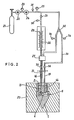
- FIG. 1 shows the cylindrical-conical tip 1 of a penetrometer, secured to the lower end of a train of tubes or rods 2 dark in the ground according to conventional methods.
- the tip 1 comprises, in its cylindrical part, a bore 3 of horizontal axis 4, opening laterally.
- a small double-acting cylinder comprising an outer jacket 5 set in this bore and a piston 6, with seal 7, integral with a rod 8.
- the jacket 5 has, at its two ends, lights 9 and 10 for the supply of fluid to the jack; it is held in place by a screwed ring 11 with gasket 12, crossed by the rod 8.
- the tip 1 has two vertical channels 13 and 14, in communication by their lower ends with the respective slots 9 and 10. Finally the tip 1 has a bleed screw 15.
- the hydraulic fluid tubing 16 is surrounded by a coaxial tubing 31, containing gas, so as to cancel the parasitic expansions of the interior tubing.
- Tubing 31 is placed in communication with the gas source, via a valve 32 and the housing 27 already mentioned.
- the valve 32 allows the passage of gas either in the direction of the housing 27, or towards the flexible tube 17 by means of another tube 33, on which a drain valve 34 is provided.
- a drain valve 34 is provided to retract the rod 8
- Quick couplings without variation in volume 35 and 36 are preferably mounted between the pipes 16-31 and 17, on the one hand, and the supply and measurement circuits located in the open air, on the other hand , so as to allow easy maneuvers, as the point 1 serving as housing for the jack progresses in depth, by adding tubes or rods 2.
- FIG. 3 represents a variant of the tip 1, the elements corresponding to those of FIG. 1 being designated by the same references.
- the return force of the piston 6, for the retraction of the rod 8 is not ensured by a compressed gas circuit.
- the tubing 17, the channel 14 and the lumen 10 are eliminated.
- a calibrated helical return spring 39 is provided, housed between the outer jacket 5 and the rod 8, and compressed between one face of the piston 6 and the ring 11.
- the supply and measurement circuits can always be produced according to the diagram of Figure 2 but, of course, the gas manifold 33 is no longer necessary.
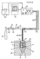
- the 6-rod piston assembly 8 is equipped with a magnetic core 40, and the jacket. 5 comprises electromagnetic windings 41 constituting two coils connected in half-bridge, so that the movement of the core 40 inside these coils determines an inductive imbalance, the whole forming a conventional inductive displacement sensor.
- the pressure allowing the horizontal penetration of the rod 8 into the ground 20 is supplied by a bottle of compressed gas 21, and transmitted to one face of the piston 6 via a tubing 16, a channel 13 and a light 9.
- This pressure is measured by a pressure gauge 25 located at the outlet of a regulator 24; the pneumatic pressure is applied either directly or via a hydraulic fluid as in the diagram in FIG. 2.
- the means here used for the retraction of the rod 8 are not shown, for the clarity of the drawing, but they can, of course, be produced according to the solutions illustrated in FIGS. 1 to 3.
- Each position of the rod 8 corresponds to a value of the intensity of the current necessary for balancing the bridge.
- these coils are connected to three electrical wires 42, which pass inside the flexible tube 16 and then exit therefrom by a junction box 43, located on the open air part. of said tubing 16.
- These wires 42 lead to a measurement box 44, powered by two electric batteries 45 mounted in series, and which can be connected to a tape recorder 46.
- the pressure applied to the piston 6 of the jack is measured by an electronic pressure transducer 47, placed for example on the connector 18, this transducer delivering a signal transmitted by the intermediary of additional electrical wires 48, up to the measurement box 44 possibly connected to the tape recorder 46.
- the rod 8 has been shown with a smaller diameter to that of the piston 6, but this diameter ratio can be reversed, to increase the sensitivity of the device in poorly resistant soils.
- the element housing the jack has been shown as being a cylindrical-conical point 1, itself forming a dynamic penetrometer probe, beaten in the ground by a sheep according to the usual methods in this technical field, in which case the device according to the invention allows dynamic penetration to be supplemented by a static penetration test, at any desired depth.
Claims (8)
Applications Claiming Priority (2)
| Application Number | Priority Date | Filing Date | Title |
|---|---|---|---|
| FR8001557A FR2474171A1 (fr) | 1980-01-18 | 1980-01-18 | Penetrometre statique |
| FR8001557 | 1980-01-18 |
Publications (2)
| Publication Number | Publication Date |
|---|---|
| EP0032648A1 EP0032648A1 (de) | 1981-07-29 |
| EP0032648B1 true EP0032648B1 (de) | 1985-04-10 |
Family
ID=9237841
Family Applications (1)
| Application Number | Title | Priority Date | Filing Date |
|---|---|---|---|
| EP80420145A Expired EP0032648B1 (de) | 1980-01-18 | 1980-12-17 | Statische Penetrometervorrichtung |
Country Status (4)
| Country | Link |
|---|---|
| US (1) | US4367647A (de) |
| EP (1) | EP0032648B1 (de) |
| DE (1) | DE3070486D1 (de) |
| FR (1) | FR2474171A1 (de) |
Families Citing this family (17)
| Publication number | Priority date | Publication date | Assignee | Title |
|---|---|---|---|---|
| FR2691257B1 (fr) * | 1992-05-18 | 1994-07-29 | Geodia | Penetrometre. |
| US5358057A (en) * | 1993-11-10 | 1994-10-25 | U.S. Army Corps Of Engineers As Represented By The Secretary Of The Army | Modular device for collecting multiple fluid samples from soil using a cone penetrometer |
| GB2334981B (en) * | 1998-03-02 | 2002-07-10 | Bachy Soletanche Ltd | Underream soil testing |
| US7598741B2 (en) * | 1999-12-24 | 2009-10-06 | Baker Hughes Incorporated | Method and apparatus for internal calibration in induction logging instruments |
| US6586939B1 (en) * | 1999-12-24 | 2003-07-01 | Baker Hughes Incorporated | Method and apparatus for reducing the effects of parasitic and galvanic currents in a resistivity measuring tool |
| US7652478B2 (en) * | 2004-05-07 | 2010-01-26 | Baker Hughes Incorporated | Cross-component alignment measurement and calibration |
| US7205770B2 (en) * | 2004-05-07 | 2007-04-17 | Baker Hughes Incorporated | Borehole conductivity simulator verification and transverse coil balancing |
| US7408355B1 (en) * | 2004-05-07 | 2008-08-05 | Baker Hughes Incorporated | Borehole conductivity simulator verification and transverse coil balancing |
| US7969153B2 (en) * | 2004-05-07 | 2011-06-28 | Baker Hughes Incorporated | Borehole conductivity simulator verification and transverse antenna balancing |
| US7932723B2 (en) * | 2004-05-07 | 2011-04-26 | Baker Hughes Incorporated | Borehole conductivity simulator verification and transverse coil balancing |
| US7319331B2 (en) * | 2004-05-07 | 2008-01-15 | Baker Hughes Incorporated | Two loop calibrator |
| DE102005038313B4 (de) * | 2005-08-11 | 2007-11-29 | Rohrvortrieb Diez Gmbh & Co. Kg | Verfahren zur Messung der geologischen Lagerungsdichte und zur Detektion von Hohlräumen im Bereich eines Vortriebstunnels |
| US7915895B2 (en) * | 2007-06-22 | 2011-03-29 | Baker Hughes Incorporated | Method of calibrating an azimuthal inductive cross-coil or tilted coil instrument |
| CN102174808B (zh) * | 2011-02-24 | 2012-12-19 | 中国地质大学(武汉) | 一种双变形柱孔压静力触探探头 |
| US8776583B2 (en) * | 2011-07-29 | 2014-07-15 | Diego Marchetti | Device comprising an automated cableless dilatometer |
| JP6887842B2 (ja) * | 2017-03-22 | 2021-06-16 | 大成建設株式会社 | 地盤探査方法および貫入試験機 |
| CN109025966A (zh) * | 2018-10-09 | 2018-12-18 | 重庆欣雨压力容器制造有限责任公司 | 一种测量页岩气井口流体质量流量的复合式装置及方法 |
Citations (4)
| Publication number | Priority date | Publication date | Assignee | Title |
|---|---|---|---|---|
| DE568912C (de) * | 1931-04-05 | 1933-01-26 | Georg Herrmann | Einrichtung zur Ermittlung der Bodendruckfestigkeit |
| FR1587397A (de) * | 1968-09-27 | 1970-03-20 | ||
| US3872717A (en) * | 1972-01-03 | 1975-03-25 | Nathaniel S Fox | Soil testing method and apparatus |
| FR2425650A1 (fr) * | 1978-05-12 | 1979-12-07 | Anvar | Procedes et dispositifs pour mesurer les caracteristiques mecaniques des sols en place |
Family Cites Families (3)
| Publication number | Priority date | Publication date | Assignee | Title |
|---|---|---|---|---|
| NL7301924A (de) * | 1973-02-09 | 1974-08-13 | ||
| IT1023139B (it) * | 1974-10-31 | 1978-05-10 | Marchetti Silvano | Dispositivo a membrane piane espandibili per la misura in sito del modulo di deformabilita dei terreni non richiedente la esecuzione dei fori di sondaggio |
| US3961524A (en) * | 1975-05-06 | 1976-06-08 | The United States Of America As Represented By The Secretary Of The Interior | Method and apparatus for determining rock stress in situ |
-
1980
- 1980-01-18 FR FR8001557A patent/FR2474171A1/fr active Granted
- 1980-12-17 EP EP80420145A patent/EP0032648B1/de not_active Expired
- 1980-12-17 DE DE8080420145T patent/DE3070486D1/de not_active Expired
-
1981
- 1981-01-19 US US06/226,405 patent/US4367647A/en not_active Expired - Lifetime
Patent Citations (4)
| Publication number | Priority date | Publication date | Assignee | Title |
|---|---|---|---|---|
| DE568912C (de) * | 1931-04-05 | 1933-01-26 | Georg Herrmann | Einrichtung zur Ermittlung der Bodendruckfestigkeit |
| FR1587397A (de) * | 1968-09-27 | 1970-03-20 | ||
| US3872717A (en) * | 1972-01-03 | 1975-03-25 | Nathaniel S Fox | Soil testing method and apparatus |
| FR2425650A1 (fr) * | 1978-05-12 | 1979-12-07 | Anvar | Procedes et dispositifs pour mesurer les caracteristiques mecaniques des sols en place |
Also Published As
| Publication number | Publication date |
|---|---|
| DE3070486D1 (en) | 1985-05-15 |
| US4367647A (en) | 1983-01-11 |
| EP0032648A1 (de) | 1981-07-29 |
| FR2474171A1 (fr) | 1981-07-24 |
| FR2474171B1 (de) | 1983-07-22 |
Similar Documents
| Publication | Publication Date | Title |
|---|---|---|
| EP0032648B1 (de) | Statische Penetrometervorrichtung | |
| EP0216706B1 (de) | Verfahren und Vorrichtung zur Messung des Brodelpunktes von Petroleum in einer unterirdischen Schicht | |
| FR2501777A1 (fr) | Methode et dispositif pour effectuer, a l'aide d'outils specialises, des operations telles que des mesures, dans des portions de puits fortement inclinees sur la verticale, ou horizontales | |
| EP0122839A1 (de) | Verfahren und Vorrichtung zum Messen und/oder Ausführen von Arbeiten in einem Bohrloch | |
| CA1274617A (fr) | Dispositif de reception d'ondes acoustiques dans un puits | |
| OA10237A (fr) | Procédé et dispositif permettant d'évaluer la perméabilité d'un milieu rocheux. | |
| EP0039278B1 (de) | Vorrichtung zum Feststellen der Festfahrstelle eines Gestänges in einem Bohrloch | |
| EP0055675B1 (de) | Verfahren und Vorrichtung zum Feststellen der Festfahrstelle eines Gestänges in einem Bohrloch | |
| US4530236A (en) | Soil investigation device | |
| CH427666A (fr) | Appareil d'essai du comportement mécanique statique du sol ou d'autres matériaux à partir d'un forage | |
| FR2529942A1 (fr) | Appareil pour determiner les caracteristiques d'ecoulement a l'interieur d'un puits | |
| FR2562150A1 (fr) | Sonde geomecanique pour puits de forage | |
| FR2496750A1 (fr) | Appareil de mesure de poids s'exercant sur un trepan de forage | |
| EP0475986B1 (de) | Verfahren und gerät zur messung vor ort der quellcharakteristik von böden | |
| FR2583876A1 (fr) | Procede et dispositif de mesure des caracteristiques de cisaillement d'un sol | |
| CA1200118A (en) | Soil investigation device | |
| FR2691257A1 (fr) | Pénétromètre. | |
| EP0705941B1 (de) | Pressiometer mit zwei Piezometer | |
| FR2564894A2 (fr) | Methode et dispositif permettant d'effectuer des mesures et/ou interventions dans un puits. | |
| FR2796151A1 (fr) | Procede et dispositif pour determiner la densite moyenne d'un fluide circulant dans un puits d'hydrocarbure incline ou horizontal | |
| FR2642791A1 (fr) | Dispositif de mesure de parametres de forage | |
| EP0346229A1 (de) | Aufstellungsvorrichtung für ein Werkzeug, speziell geeignet bei Eingriffen am Ende eines Bohrstrangs | |
| FR2682715A1 (fr) | Detecteur de venue de gaz. | |
| FR2613767A1 (fr) | Banc d'essai a echelle reduite pour simuler le comportement d'une garniture de forage | |
| FR2625767A1 (fr) | Procede et installation de mesure de la permeabilite de terrains traverses au cours de l'avancement d'un forage |
Legal Events
| Date | Code | Title | Description |
|---|---|---|---|
| PUAI | Public reference made under article 153(3) epc to a published international application that has entered the european phase |
Free format text: ORIGINAL CODE: 0009012 |
|
| AK | Designated contracting states |
Designated state(s): BE DE GB IT NL SE |
|
| 17P | Request for examination filed |
Effective date: 19820112 |
|
| GRAA | (expected) grant |
Free format text: ORIGINAL CODE: 0009210 |
|
| AK | Designated contracting states |
Designated state(s): BE DE GB IT NL SE |
|
| PG25 | Lapsed in a contracting state [announced via postgrant information from national office to epo] |
Ref country code: IT Free format text: LAPSE BECAUSE OF FAILURE TO SUBMIT A TRANSLATION OF THE DESCRIPTION OR TO PAY THE FEE WITHIN THE PRESCRIBED TIME-LIMIT;WARNING: LAPSES OF ITALIAN PATENTS WITH EFFECTIVE DATE BEFORE 2007 MAY HAVE OCCURRED AT ANY TIME BEFORE 2007. THE CORRECT EFFECTIVE DATE MAY BE DIFFERENT FROM THE ONE RECORDED. Effective date: 19850410 |
|
| PG25 | Lapsed in a contracting state [announced via postgrant information from national office to epo] |
Ref country code: SE Effective date: 19850430 |
|
| REF | Corresponds to: |
Ref document number: 3070486 Country of ref document: DE Date of ref document: 19850515 |
|
| PLBE | No opposition filed within time limit |
Free format text: ORIGINAL CODE: 0009261 |
|
| STAA | Information on the status of an ep patent application or granted ep patent |
Free format text: STATUS: NO OPPOSITION FILED WITHIN TIME LIMIT |
|
| 26N | No opposition filed | ||
| PGFP | Annual fee paid to national office [announced via postgrant information from national office to epo] |
Ref country code: GB Payment date: 19971224 Year of fee payment: 18 |
|
| PGFP | Annual fee paid to national office [announced via postgrant information from national office to epo] |
Ref country code: NL Payment date: 19971231 Year of fee payment: 18 |
|
| PGFP | Annual fee paid to national office [announced via postgrant information from national office to epo] |
Ref country code: DE Payment date: 19980109 Year of fee payment: 18 |
|
| PGFP | Annual fee paid to national office [announced via postgrant information from national office to epo] |
Ref country code: BE Payment date: 19980130 Year of fee payment: 18 |
|
| PG25 | Lapsed in a contracting state [announced via postgrant information from national office to epo] |
Ref country code: GB Free format text: LAPSE BECAUSE OF NON-PAYMENT OF DUE FEES Effective date: 19981217 |
|
| PG25 | Lapsed in a contracting state [announced via postgrant information from national office to epo] |
Ref country code: BE Free format text: LAPSE BECAUSE OF NON-PAYMENT OF DUE FEES Effective date: 19981231 |
|
| BERE | Be: lapsed |
Owner name: LABAYS JEAN-BERNARD Effective date: 19981231 Owner name: BARNOUD FRANCOIS Effective date: 19981231 |
|
| PG25 | Lapsed in a contracting state [announced via postgrant information from national office to epo] |
Ref country code: NL Free format text: LAPSE BECAUSE OF NON-PAYMENT OF DUE FEES Effective date: 19990701 |
|
| GBPC | Gb: european patent ceased through non-payment of renewal fee |
Effective date: 19981217 |
|
| NLV4 | Nl: lapsed or anulled due to non-payment of the annual fee |
Effective date: 19990701 |
|
| PG25 | Lapsed in a contracting state [announced via postgrant information from national office to epo] |
Ref country code: DE Free format text: LAPSE BECAUSE OF NON-PAYMENT OF DUE FEES Effective date: 19991001 |