EP0032648B1 - Static penetrometer - Google Patents
Static penetrometer Download PDFInfo
- Publication number
- EP0032648B1 EP0032648B1 EP80420145A EP80420145A EP0032648B1 EP 0032648 B1 EP0032648 B1 EP 0032648B1 EP 80420145 A EP80420145 A EP 80420145A EP 80420145 A EP80420145 A EP 80420145A EP 0032648 B1 EP0032648 B1 EP 0032648B1
- Authority
- EP
- European Patent Office
- Prior art keywords
- rod
- ground
- pressure
- jack
- static penetrometer
- Prior art date
- Legal status (The legal status is an assumption and is not a legal conclusion. Google has not performed a legal analysis and makes no representation as to the accuracy of the status listed.)
- Expired
Links
Images

Classifications
-
- G—PHYSICS
- G01—MEASURING; TESTING
- G01N—INVESTIGATING OR ANALYSING MATERIALS BY DETERMINING THEIR CHEMICAL OR PHYSICAL PROPERTIES
- G01N3/00—Investigating strength properties of solid materials by application of mechanical stress
- G01N3/40—Investigating hardness or rebound hardness
-
- E—FIXED CONSTRUCTIONS
- E02—HYDRAULIC ENGINEERING; FOUNDATIONS; SOIL SHIFTING
- E02D—FOUNDATIONS; EXCAVATIONS; EMBANKMENTS; UNDERGROUND OR UNDERWATER STRUCTURES
- E02D1/00—Investigation of foundation soil in situ
- E02D1/02—Investigation of foundation soil in situ before construction work
- E02D1/022—Investigation of foundation soil in situ before construction work by investigating mechanical properties of the soil
-
- G—PHYSICS
- G01—MEASURING; TESTING
- G01N—INVESTIGATING OR ANALYSING MATERIALS BY DETERMINING THEIR CHEMICAL OR PHYSICAL PROPERTIES
- G01N2203/00—Investigating strength properties of solid materials by application of mechanical stress
- G01N2203/0001—Type of application of the stress
- G01N2203/0012—Constant speed test
-
- G—PHYSICS
- G01—MEASURING; TESTING
- G01N—INVESTIGATING OR ANALYSING MATERIALS BY DETERMINING THEIR CHEMICAL OR PHYSICAL PROPERTIES
- G01N2203/00—Investigating strength properties of solid materials by application of mechanical stress
- G01N2203/0058—Kind of property studied
- G01N2203/0076—Hardness, compressibility or resistance to crushing
Definitions
- the present invention relates to a static penetrometer, of the type comprising an element lowered into the ground and serving as a housing for a cylinder of substantially horizontal axis, the piston of which, subjected on at least one of its faces to the pressure of a fluid hydraulic or pneumatic, is integral with a rod capable of being inserted laterally into the ground or retracted inside the above-mentioned element, means being provided for locating the position of said rod and measuring the pressure exerted on it , said element being integral with the lower end of a drill string for lowering said element into the ground, this element also being connected to hydraulic or pneumatic fluid pipes as well as to other connecting lines.
- Such an apparatus makes it possible to carry out penetration tests for the recognition of soils and, more particularly for the "in situ” measurement of the static resistance of soils.
- the penetration test a means of recognizing commonly used soils, usually consists of sinking into the ground, from top to bottom, a probe placed at the lower end of a train of tubes or rods.
- This sinking can be carried out: either by threshing, by means of a sheep which strikes an anvil secured to the top of the train of tubes or rods, the device then being called “dynamic penetrometer”; either by slow speed actuation, in which case it is a "static penetrometer”.
- the present invention aims to remedy these drawbacks; its purpose is therefore to provide a device which can be directly dark in the ground, without prior drilling, ensuring perfect protection of the fluid pipes and other connections existing between the device and the surface, and providing a maximum stroke of the rod pressed laterally into the ground while ensuring adequate reaction to the penetration of this rod.
- the element serving as housing for the above-mentioned jack is a cylindro-conical point capable of being dark in the ground, the force of reaction to the insertion of the rod the ground being provided by the lateral contact of this cylindrical-conical point on the ground, and the rods of said string of rods are constituted by tubes enclosing the fluid tubes and the other connecting lines.
- the static penetration test is carried out along a horizontal axis, at any desired depth, by means of a preferably double-acting cylinder, housed inside a cylindro-conical point, of large diameter in its cylindrical part, dark point in the ground via the train of tubes which also has the function of ensuring the protection of the hydraulic or pneumatic fluid pipes as well as the electrical connections.
- the force of reaction to the penetration of the rod is provided by the lateral contact on the ground of the dark element and can be very much greater than the penetration force, taking into account the ratio of the surfaces of the rod and of the dark element.
- the rod can thus be introduced into the ground under a known pressure, then retracted at the end of the test into its housing, so as to continue the vertical sinking of the element which contains it, before carrying out a new test at another depth.
- the device thus allows, by pressure and displacement measurements, to know the resistance to static penetration of the soil, the interpretation of the test being the same as for a conventional static penetration test, the only difference being that the measurement is made along an axis horizontal; reading the pressure at the various stages of sinking the rod allows the resistance of the soil to be measured at a given depth.
- the invention gives rise to various embodiments, according to the means provided for moving the rod, in the direction of its insertion into the ground and of its retraction, and for measuring pressures and displacements.
- the pressure on the piston of the cylinder of horizontal axis is exerted, at least in the direction of the insertion of the rod into the ground, by means of a hydraulic fluid pressurized by a compressed gas supplied by a gas source, means being provided for measuring the pressure and the volume thereof, in order to know the resistance of the soil and to identify the position of the rod.
- the cylinder can be double-acting, in which case it is the aforementioned gas which, acting directly on the other face of the piston, makes it possible to retract the rod.
- the return force can be provided by a helical spring.
- two flexible tubes or only one, provide the connection between the apparatus located in the open air and the element lowered into the ground which contains the cylinder with a horizontal axis.
- the flexible tubing which encloses the hydraulic fluid is surrounded by a coaxial tubing, containing gas, in order to cancel the parasitic expansions of the interior tubing.
- the pressure on the piston of the cylinder of horizontal axis is exerted, at least in the direction of the insertion of the rod into the ground, by means of a fluid either pneumatic or hydraulic, but the position of the rod is identified by an electric or electronic displacement sensor, of the inductive type for example.
- an electric or electronic displacement sensor of the inductive type for example.
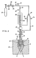
- FIG. 1 shows the cylindrical-conical tip 1 of a penetrometer, secured to the lower end of a train of tubes or rods 2 dark in the ground according to conventional methods.
- the tip 1 comprises, in its cylindrical part, a bore 3 of horizontal axis 4, opening laterally.
- a small double-acting cylinder comprising an outer jacket 5 set in this bore and a piston 6, with seal 7, integral with a rod 8.
- the jacket 5 has, at its two ends, lights 9 and 10 for the supply of fluid to the jack; it is held in place by a screwed ring 11 with gasket 12, crossed by the rod 8.
- the tip 1 has two vertical channels 13 and 14, in communication by their lower ends with the respective slots 9 and 10. Finally the tip 1 has a bleed screw 15.
- the hydraulic fluid tubing 16 is surrounded by a coaxial tubing 31, containing gas, so as to cancel the parasitic expansions of the interior tubing.
- Tubing 31 is placed in communication with the gas source, via a valve 32 and the housing 27 already mentioned.
- the valve 32 allows the passage of gas either in the direction of the housing 27, or towards the flexible tube 17 by means of another tube 33, on which a drain valve 34 is provided.
- a drain valve 34 is provided to retract the rod 8
- Quick couplings without variation in volume 35 and 36 are preferably mounted between the pipes 16-31 and 17, on the one hand, and the supply and measurement circuits located in the open air, on the other hand , so as to allow easy maneuvers, as the point 1 serving as housing for the jack progresses in depth, by adding tubes or rods 2.
- FIG. 3 represents a variant of the tip 1, the elements corresponding to those of FIG. 1 being designated by the same references.
- the return force of the piston 6, for the retraction of the rod 8 is not ensured by a compressed gas circuit.
- the tubing 17, the channel 14 and the lumen 10 are eliminated.
- a calibrated helical return spring 39 is provided, housed between the outer jacket 5 and the rod 8, and compressed between one face of the piston 6 and the ring 11.
- the supply and measurement circuits can always be produced according to the diagram of Figure 2 but, of course, the gas manifold 33 is no longer necessary.
- the 6-rod piston assembly 8 is equipped with a magnetic core 40, and the jacket. 5 comprises electromagnetic windings 41 constituting two coils connected in half-bridge, so that the movement of the core 40 inside these coils determines an inductive imbalance, the whole forming a conventional inductive displacement sensor.
- the pressure allowing the horizontal penetration of the rod 8 into the ground 20 is supplied by a bottle of compressed gas 21, and transmitted to one face of the piston 6 via a tubing 16, a channel 13 and a light 9.
- This pressure is measured by a pressure gauge 25 located at the outlet of a regulator 24; the pneumatic pressure is applied either directly or via a hydraulic fluid as in the diagram in FIG. 2.
- the means here used for the retraction of the rod 8 are not shown, for the clarity of the drawing, but they can, of course, be produced according to the solutions illustrated in FIGS. 1 to 3.
- Each position of the rod 8 corresponds to a value of the intensity of the current necessary for balancing the bridge.
- these coils are connected to three electrical wires 42, which pass inside the flexible tube 16 and then exit therefrom by a junction box 43, located on the open air part. of said tubing 16.
- These wires 42 lead to a measurement box 44, powered by two electric batteries 45 mounted in series, and which can be connected to a tape recorder 46.
- the pressure applied to the piston 6 of the jack is measured by an electronic pressure transducer 47, placed for example on the connector 18, this transducer delivering a signal transmitted by the intermediary of additional electrical wires 48, up to the measurement box 44 possibly connected to the tape recorder 46.
- the rod 8 has been shown with a smaller diameter to that of the piston 6, but this diameter ratio can be reversed, to increase the sensitivity of the device in poorly resistant soils.
- the element housing the jack has been shown as being a cylindrical-conical point 1, itself forming a dynamic penetrometer probe, beaten in the ground by a sheep according to the usual methods in this technical field, in which case the device according to the invention allows dynamic penetration to be supplemented by a static penetration test, at any desired depth.
Description
La présente invention concerne un pénétromètre statique, du genre comprenant un élément descendu dans le sol et servant de logement à un vérin d'axe sensiblement horizontal dont le piston, soumis sur l'une au moins de ses faces à la pression d'un fluide hydraulique on pneumatique, est solidaire d'une tige apte à être enfoncée latéralement dans le sol ou rétractée à l'intérieur de l'élément précité, des moyens étant prévus pour repérer la position de ladite tige et mesurer la pression exercée sur celle-ci, ledit élément étant solidaire de l'extrémité inférieure d'un train de tiges servant à descendre ledit élément dans le sol, cet élément étant aussi relié à des tubulures de fluide hydraulique ou pneumatique ainsi qu'à d'autres lignes de liaison.The present invention relates to a static penetrometer, of the type comprising an element lowered into the ground and serving as a housing for a cylinder of substantially horizontal axis, the piston of which, subjected on at least one of its faces to the pressure of a fluid hydraulic or pneumatic, is integral with a rod capable of being inserted laterally into the ground or retracted inside the above-mentioned element, means being provided for locating the position of said rod and measuring the pressure exerted on it , said element being integral with the lower end of a drill string for lowering said element into the ground, this element also being connected to hydraulic or pneumatic fluid pipes as well as to other connecting lines.
Un tel appareil permet d'effectuer des essais de pénétration en vue de la reconnaissance des sols et, plus particulièrement de la mesure "in situ" de la résistance statique des sols.Such an apparatus makes it possible to carry out penetration tests for the recognition of soils and, more particularly for the "in situ" measurement of the static resistance of soils.
L'essai de pénétration, moyen de reconnaissance des, sols couramment utilisé, consiste habituellement à foncer dans le sol, de haut en bas, une sonde placée à l'extrémité inférieure d'un train de tubes ou de tiges. Ce fonçage peut s'effectuer: soit par battage, au moyen d'un mouton qui vient frapper une enclume solidaire du sommet du train de tubes ou de tiges, le dispositif étant alors appelé "pénétromètre . dynamique"; soit par vérinage à vitesse lente, auquel cas il s'agit d'un "pénétromètre statique". La réaction, qu'il convient d'exercer pour foncer un tel pénétromètre statique, et qui devient considérable dès que le sol est compact, est fournie soit par des ancrages, soit par le poids du véhicule sur lequel est fixé l'appareil, ce qui impose l'emploi de dispositifs encombrants et parfois inefficaces (ancrages), ou d'un engin sur roues lourd (15 à 18 tonnes) qu'il n'est pas toujours possible d'amener sur les sites "difficiles".The penetration test, a means of recognizing commonly used soils, usually consists of sinking into the ground, from top to bottom, a probe placed at the lower end of a train of tubes or rods. This sinking can be carried out: either by threshing, by means of a sheep which strikes an anvil secured to the top of the train of tubes or rods, the device then being called "dynamic penetrometer"; either by slow speed actuation, in which case it is a "static penetrometer". The reaction, which should be exerted to sink such a static penetrometer, and which becomes considerable as soon as the ground is compact, is provided either by anchors, or by the weight of the vehicle on which the apparatus is fixed, this which requires the use of bulky and sometimes ineffective devices (anchors), or a heavy wheeled vehicle (15 to 18 tonnes) that it is not always possible to bring to "difficult" sites.
D'autres appareils, appartenant au genre indiqué en introduction, sont des pénétromètres statiques dans lesquels l'enfoncement vertical est remplacé par un enfoncement latéral d'une tige poussée par un vérin d'axe horizontal, logé à l'intérieur d'un élément descendu dans lé sol. Un tel appareil est décrit par le brevet US-A-3 872 717, où l'élément descendu dans le sol est un corps de forme cylindrique, fixé à l'extrémité inférieure d'un train de tiges pleines, et muni de stabilisateurs latéraux qui assurent la réaction à l'effort de pénétration de la tige latérale. Cet appareil possède les inconvénients suivants:
- - En raison de la forme cylindrique de l'élément descendu dans le sol, l'appareil ne peut être utilisé qu'après forage préalable d'un trou dans le sol.
- - Le train de tiges pleines ne permet pas une protection des tubulures de fluide et des liaisons électriques reliant l'élément introduit dans le trou à l'appareillage situé à la surface.
- - Les stabilisateurs latéraux offrent une surface limitée pour absorber la réaction à l'enfoncement de la tige latérale, et la présence de ces stabilisateurs, relativement encombrants, réduit le diamètre utile de l'élément descendu dans le sol, donc limite la course de la tige latérale à une valeur faible, relativement au diamètre du forage.
- - Due to the cylindrical shape of the element lowered into the ground, the device can only be used after previously drilling a hole in the ground.
- - The train of solid rods does not allow protection of the fluid pipes and of the electrical connections connecting the element introduced into the hole to the apparatus located on the surface.
- - The lateral stabilizers offer a limited surface to absorb the reaction to the sinking of the lateral rod, and the presence of these relatively bulky stabilizers reduces the useful diameter of the element lowered into the ground, thus limiting the stroke of the lateral rod at a low value, relative to the diameter of the borehole.
Un autre appareil partiellement similaire au précédent est décrit dans la demande de brevet français FR-A-2 425 650. Cet appareil comporte toujours un corps de forme cylindrique qui doit être descendu dans un trou préalablement foré et muni d'un tubage. L'appareil comporte deux vérins diamétralement opposés, d'axe horizontal, qui déplacent des sabots latéraux, lesquels constituent des moyens d'ancrage et non pas des moyens de mesure de la résistance du sol à la pénétration d'un tige. Même s'il s'agissait de tiges permettant une mesure, leur course serait là aussi bien faible, relativement au diamètre du forage, en raison de la disposition avec deux vérins diamétralement opposés. Enfin, cet appareil est simplement suspendu à un câble et/ou à des tubulures hydrauliques, et non pas maintenu mécaniquement à l'extrémité inférieure d'un train de tiges.Another device partially similar to the previous one is described in French patent application FR-A-2 425 650. This device always comprises a body of cylindrical shape which must be lowered into a hole previously drilled and provided with a casing. The apparatus comprises two diametrically opposite cylinders, of horizontal axis, which move lateral shoes, which constitute anchoring means and not means for measuring the resistance of the soil to the penetration of a rod. Even if they were rods allowing a measurement, their stroke would also be very small, relative to the diameter of the borehole, due to the arrangement with two diametrically opposed cylinders. Finally, this device is simply suspended from a cable and / or hydraulic pipes, and not mechanically held at the lower end of a drill string.
La présente invention vise à remédier à ces inconvénients; son but est donc de fournir un appareil pouvant être directement foncé dans le sol, sans forage préalable, assurant une parfaite protection des tubulures de fluide et autres liaisons existant entre l'appareil et la surface, et procurant une course maximale de la tige enfoncée latéralement dans le sol tout en assurant convenablement la réaction à l'enfoncement de cette tige.The present invention aims to remedy these drawbacks; its purpose is therefore to provide a device which can be directly dark in the ground, without prior drilling, ensuring perfect protection of the fluid pipes and other connections existing between the device and the surface, and providing a maximum stroke of the rod pressed laterally into the ground while ensuring adequate reaction to the penetration of this rod.
A cet effet, dans le pénétromètre statique objet de l'invention, l'élément servant de logement au vérin précité est une pointe cylindro-conique apte à être foncée dans le sol, l'effort de réaction à l'enfoncement de la tige dans le sol étant fourni par le contact latéral de cette pointe cylindro-conique sur le sol, et les tiges dudit train de tiges sont constituées par des tubes renfermant les tubulures de fluide et les autres lignes de liaison.To this end, in the static penetrometer which is the subject of the invention, the element serving as housing for the above-mentioned jack is a cylindro-conical point capable of being dark in the ground, the force of reaction to the insertion of the rod the ground being provided by the lateral contact of this cylindrical-conical point on the ground, and the rods of said string of rods are constituted by tubes enclosing the fluid tubes and the other connecting lines.
Avec un tel appareil, l'essai de pénétration statique s'effectue suivant un axe horizontal, à toute profondeur souhaitée, au moyen d'un vérin de préférence à double effet, logé à l'intérieur d'une pointe cylindro-conique, de diamètre important dans sa partie cylindrique, pointe foncée dans le sol par l'intermédiaire du train de tubes qui a aussi pour fonction d'assurer la protection des tubulures de fluide hydraulique ou pneumatique ainsi qui des liaisons électriques. L'effort de réaction à l'enfoncement de la tige est fourni par le contact latéral sur le sol de l'élément foncé et peut être très nettement supérieur à l'effort de pénétration, compte tenu du rapport des surfaces de la tige et de l'élément foncé. La tige peut ainsi être introduite dans le sol sous une pression connue, puis rétractée à la fin de l'essai dans son logement, de manière à poursuivre le fonçage vertical de l'élément qui la contient, avant d'effectuer un nouvel essai à une autre profondeur. L'appareil permet ainsi, par des mesures de pression et de déplacement, de connaître la résistance à la pénétration statique du sol, l'interprétation de l'essai étant la même que pour un essai de pénétration statique classique, la seule différence étant que la mesure s'effectue selon un axe horizontal; la lecture de la pression aux différents stades d'enfoncement de la tige permet une mesure de la résistance du sol, à une profondeur donnée. Si l'on désire effectuer des mesures selon plusieurs directions, à une même profondeur, il est possible, une fois la tige rétractée, de faire pivoter l'élément foncé ou foré, autour de son axe vertical, d'un angle voulu, et de procéder alors à un second essai selon une autre direction; l'opération peut être, éventuellement, répétée une troisième, une quatrième fois ...With such an apparatus, the static penetration test is carried out along a horizontal axis, at any desired depth, by means of a preferably double-acting cylinder, housed inside a cylindro-conical point, of large diameter in its cylindrical part, dark point in the ground via the train of tubes which also has the function of ensuring the protection of the hydraulic or pneumatic fluid pipes as well as the electrical connections. The force of reaction to the penetration of the rod is provided by the lateral contact on the ground of the dark element and can be very much greater than the penetration force, taking into account the ratio of the surfaces of the rod and of the dark element. The rod can thus be introduced into the ground under a known pressure, then retracted at the end of the test into its housing, so as to continue the vertical sinking of the element which contains it, before carrying out a new test at another depth. The device thus allows, by pressure and displacement measurements, to know the resistance to static penetration of the soil, the interpretation of the test being the same as for a conventional static penetration test, the only difference being that the measurement is made along an axis horizontal; reading the pressure at the various stages of sinking the rod allows the resistance of the soil to be measured at a given depth. If one wishes to carry out measurements in several directions, at the same depth, it is possible, once the rod retracted, to rotate the dark or drilled element, about its vertical axis, by a desired angle, and then to carry out a second test in another direction; the operation can be, possibly, repeated a third, a fourth time ...
L'invention donne lieu à diverses formes de réalisation, suivant les moyens prévus pour déplacer la tige, dans le sens de son enfoncement dans le sol et de sa rétraction, et pour mesurer pressions et déplacements.The invention gives rise to various embodiments, according to the means provided for moving the rod, in the direction of its insertion into the ground and of its retraction, and for measuring pressures and displacements.
Dans une première forme de réalisation, la pression sur le piston du vérin d'axe horizontal est exercée, au moins dans le sens de l'enfoncement de la tige dans le sol, par l'intermédiaire d'un fluide hydraulique mis en pression par un gaz comprimé fourni par une source de gaz, des moyens étant prévus pour mesurer la pression et le volume de ce dernier, en vue de connaître la résistance du sol et repérer la position de la tige. Le vérin peut être à double effet, auquel cas c'est le gaz précité qui, agissant directement sur l'autre face du piston, permet de rétracter la tige. En variante, toujours dans le cas ici considéré où un liquide transmet la pression destinée à enfoncer la tige dans le sol et permet également le repérage en position de cette tige, l'effort de rappel, tendant à rétracter ladite tige, peut être fourni par un ressort hélicoïdal. Selon le cas, deux tubulures souples, ou une seule, assurent la liaison entre l'appareillage situé à l'air libre et l'élément descendu dans le sol qui renferme le vérin d'axe horizontal. De préférence, la tubulure souple qui renferme le fluide hydraulique est entourée d'une tubulure coaxiale, contenant du gaz, afin d'annuler les dilatations parasites de la tubulure intérieure.In a first embodiment, the pressure on the piston of the cylinder of horizontal axis is exerted, at least in the direction of the insertion of the rod into the ground, by means of a hydraulic fluid pressurized by a compressed gas supplied by a gas source, means being provided for measuring the pressure and the volume thereof, in order to know the resistance of the soil and to identify the position of the rod. The cylinder can be double-acting, in which case it is the aforementioned gas which, acting directly on the other face of the piston, makes it possible to retract the rod. As a variant, still in the case considered here where a liquid transmits the pressure intended to drive the rod into the ground and also allows the locating of this rod in position, the return force, tending to retract said rod, can be provided by a helical spring. Depending on the case, two flexible tubes, or only one, provide the connection between the apparatus located in the open air and the element lowered into the ground which contains the cylinder with a horizontal axis. Preferably, the flexible tubing which encloses the hydraulic fluid is surrounded by a coaxial tubing, containing gas, in order to cancel the parasitic expansions of the interior tubing.
Dans une autre forme de réalisation, la pression sur le piston du vérin d'axe horizontal est exercée, au moins dans le sens de l'enfoncement de la tige dans le sol, par l'intermédiaire d'un fluide indifféremment pneumatique ou hydraulique, mais la position de la tige est repérée par un capteur de déplacement électrique ou électronique, du type inductif par exemple. Pour la mesure de la pression pneumatique ou hydraulique s'appliquant sur le piston du vérin, on peut dans ce cas utiliser également un transducteur électronique; une mesure manométrique reste cependant possible.In another embodiment, the pressure on the piston of the cylinder of horizontal axis is exerted, at least in the direction of the insertion of the rod into the ground, by means of a fluid either pneumatic or hydraulic, but the position of the rod is identified by an electric or electronic displacement sensor, of the inductive type for example. For the measurement of the pneumatic or hydraulic pressure applied to the piston of the jack, it is also possible in this case to use an electronic transducer; a manometric measurement remains however possible.
De toute façon, l'invention sera bien comprise à l'aide de la description qui suit, en référence au dessin schématique annexé représentant, à titre d'exemples non limitatifs, quelques formes de réalisation de ce pénétromètre statique:
- Figure 1 est une vue en coupe verticale, passant par l'axe, de la pointe d'un pénétromètre conforme à l'invention;
- Figure 2 représente, très schématiquement, les circuits d'alimentation et de mesure associés à la pointe de la figure 1;
- Figure 3 montre, en coupe verticale passant par l'axe, une variante de la pointe selon la figure 1;
- Figure 4 représente, en coupe verticale passant par l'axe, encore une autre forme de réalisation de la pointe d'un pénétromètre conforme à l'invention;
- Figure 5 est une vue, très schématique, des circuits d'alimentation et de mesure associés à la pointe de la figure 4.
- Figure 1 is a vertical sectional view, passing through the axis, of the tip of a penetrometer according to the invention;
- Figure 2 shows, very schematically, the supply and measurement circuits associated with the tip of Figure 1;
- Figure 3 shows, in vertical section passing through the axis, a variant of the tip according to Figure 1;
- Figure 4 shows, in vertical section passing through the axis, yet another embodiment of the tip of a penetrometer according to the invention;
- Figure 5 is a very schematic view of the supply and measurement circuits associated with the tip of Figure 4.
La figure 1 montre la pointe cylindro-conique 1 d'un pénétromètre, solidaire de l'extrémité inférieure d'un train de tubes ou de tiges 2 foncé dans le sol selon les procédés classiques. La pointe 1 comporte, dans sa partie cylindrique, un alésage 3 d'axe horizontal 4, débouchant latéralement. Dans l'alésage 3 est logé un petit vérin à double effet, comprenant une chemise extérieure 5 sertie dans cet alésage et un piston 6, avec joint d'étanchéité 7, solidaire d'une tige 8. La chemise 5 présente, à ses deux extrémités, des lumières 9 et 10 pour l'alimentation en fluide du vérin; elle est maintenue en place par une bague vissée 11 avec joint d'étanchéité 12, traversée par la tige 8. La pointe 1 possède deux canaux verticaux 13 et 14, en communication par leurs extrémités inférieures avec les lumières respectives 9 et 10. Enfin la pointe 1 comporte une vis de purge 15.Figure 1 shows the cylindrical-conical tip 1 of a penetrometer, secured to the lower end of a train of tubes or rods 2 dark in the ground according to conventional methods. The tip 1 comprises, in its cylindrical part, a bore 3 of horizontal axis 4, opening laterally. In the bore 3 is housed a small double-acting cylinder, comprising an outer jacket 5 set in this bore and a
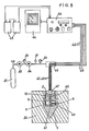
Des fluides sous pression sont amenés à l'ensemble précédemment décrit au moyen de tubulures souples 16 et 17, connectées aux extrémités supérieures de canaux 13 et 14 par l'intermédiaire de raccords respectifs 18 et 19. Un fluide hydraulique agit sur la face du piston 6 opposée à la tige 8, et force cette dernière à pénétrer horizontalement dans le sol 20, comme illustré très schématiquement sur la figure 2 qui montre, également, les circuits d'alimentation et de mesure, décrits ci-après:
- Le fluide hydraulique est mis en pression par l'intermédiaire d'un gaz comprimé (air ou azote), fourni par une
bouteille 21 équipée d'undétendeur 22 et d'unmanomètre 23. Unsecond détendeur 24 permet de régler finement la pression mesurée par un manomètre deprécision 25. Ce circuit pneumatique est relié à une tubulure transparente et graduée 26, aboutissant à unboîtier 27, auquel est raccordée aussi la tubulure souple 16. La surface de séparation gaz-fluide hydraulique 28 est située en regard des graduations de latubulure 26, et ceci permet de connaître avec précision la position de latige 8, lorsque celle-ci pénètre dans lesol 20. Le gaz est admis dans la tubulure transparente et graduée 26 au travers d'unevanne 29, en aval de laquelle est encore prévu un robinet depurge 30.
- The hydraulic fluid is pressurized by means of a compressed gas (air or nitrogen), supplied by a
bottle 21 equipped with aregulator 22 and apressure gauge 23. Asecond regulator 24 makes it possible to finely adjust the pressure measured by aprecision pressure gauge 25. This pneumatic circuit is connected to a transparent and graduatedtubing 26, leading to ahousing 27, to which is also connected theflexible tubing 16. The gas-hydraulicfluid separation surface 28 is located opposite the graduations of thetubing 26, and this makes it possible to know with precision the position of therod 8, when the latter penetrates into theground 20. The gas is admitted into the transparent and graduatedtubing 26 through avalve 29, in downstream of which apurge valve 30 is still provided.
La tubulure de fluide hydraulique 16 est entourée d'une tubulure coaxiale 31, contenant du gaz, de manière à annuler les dilatations parasites de la tubulure intérieure. La tubulure 31 est mise en communication avec la source de gaz, par l'intermédiaire d'une vanne 32 et du boîtier 27 déjà mentionné.The
La vanne 32 permet le passage du gaz soit en direction du boîtier 27, soit vers la tubulure souple 17 par l'intermédiaire d'une autre tubulure 33, sur laquelle est prévu un robinet de purge 34. Pour rétracter la tige 8, on coupe la pression du circuit hydraulique, au moyen de la vanne 29 et du robinet de purge 30, et l'on applique une pression de gaz sur la face du piston 6 située du côté de la tige 8; à cet effet, la vanne 32 est basculée en direction des tubulures 33 et 17, après fermeture du robinet de purge 34.The
Des raccords rapides sans variation de volume 35 et 36 sont, de préférence, montés entre les tubulures 16-31 et 17, d'une part, et les circuits d'alimentation et de mesure situés à l'air libre, d'autre part, de manière à permettre de manoeuvres faciles, au fur et à mesure que la pointe 1 servant de logement au vérin progresse en profondeur, par adjonction de tubes ou de tiges 2.Quick couplings without variation in
L'ensemble des circuits est encore complété par deux autres robinets de purge 37 et 38.All the circuits are further completed by two
La figure 3 représente une variante de la pointe 1, les éléments correspondant à ceux de la figure 1 étant désignés par les mêmes répères. A la différence de la première forme de réalisation précédemment décrite, l'effort de rappel du piston 6, pour la rétraction de la tige 8, n'est pas assuré par un circuit de gaz comprimé. Ainsi la tubulure 17, le canal 14 et la lumière 10 sont supprimés. A la place, est prévu un ressort de rappel hélicoïdal taré 39, logé entre la chemise extérieure 5 et la tige 8, et comprimé entre une face du piston 6 et la bague 11. Les circuits d'alimentation et de mesure peuvent toujours être réalisés selon le schéma de la figure 2 mais, bien entendu, la tubulure de gaz 33 n'est alors plus nécessaire.FIG. 3 represents a variant of the tip 1, the elements corresponding to those of FIG. 1 being designated by the same references. Unlike the first embodiment described above, the return force of the
Dans une autre forme de réalisation, illustrée par les figures 4 et 5, l'ensemble piston 6-tige 8 est équipé d'un noyau magnétique 40, et la chemise. 5 comprend des enroulements électro-magnétiques 41 constituant deux bobines connectées en demi-pont, de sorte que le mouvement du noyau 40 à l'intérieur de ces bobines détermine un déséquilibre inductif, le tout formant un capteur inductif de déplacement classique.In another embodiment, illustrated by FIGS. 4 and 5, the 6-
Comme dans la première forme de réalisation décrite, la pression permettant la pénétration horizontale de la tige 8 dans le sol 20 est fournie par une bouteille de gaz comprimé 21, et transmise jusqu'à une face du piston 6 par l'intermédiaire d'une tubulure 16, d'un canal 13 et d'une lumière 9. Cette pression est mesurée par un manomètre 25 situé à la sortie d'un détendeur 24; la pression pneumatique est appliquée soit directement, soit par l'intermédiaire d'un fluide hydraulique comme sur le schéma de la figure 2. Les moyens ici utilisés pour la rétraction de la tige 8 ne sont pas représentés, pour la clarté du dessin, mais ils peuvent, bien entendu, être réalisés suivant les solutions illustrées par les figures 1 à 3.As in the first embodiment described, the pressure allowing the horizontal penetration of the
A chaque position de la tige 8 correspond une valeur de l'intensité du courant nécessaire à l'équilibrage du pont. Pour alimenter les bobines 41 et effectuer la mesure, ces bobines sont raccordées à trois fils électriques 42, qui passent à l'intérieur de la tubulure souple 16 puis en sortent par un boîtier de dérivation 43, situé sur la partie à l'air libre de ladite tubulure 16. Ces fils 42 aboutissent à un boîtier de mesure 44, alimenté par deux piles électriques 45 montées en série, et pouvant être relié à un enregistreur à bande 46.Each position of the
Dans une variante illustrée par les mêmes figures 4 et 5, la pression s'appliquant sur le piston 6 du vérin est mesurée par un transducteur électronique de pression 47, placé par exemple sur le raccord 18, ce transducteur délivrant un signal transmis, par l'intermédiaire de fils électriques supplémentaires 48, jusqu'au boîtier de mesure 44 éventuellement relié à l'enregistreur à bande 46.In a variant illustrated by the same Figures 4 and 5, the pressure applied to the
On peut aussi équiper la tige 8 d'un capteur de déplacement, de type potentiomètre linéaire, dont la variation de résistance devient, alors, la grandeur mesurée par le boîtier 44. Sur les figures, la tige 8 a été représentée avec un diamètre inférieur à celui du piston 6, mais ce rapport de diamètres peut être inversé, pour accroître la sensibilité de l'appareil dans les sols peu résistants.One can also equip the
L'élément logeant le vérin a été représenté comme étant une pointe cylindro-conique 1, formant ellemême une sonde de pénétromètre dynamique, battue dans le sol par un mouton selon les procédés habituels dans ce domaine technique, auquel cas le dispositif selon l'invention permet de compléter la pénétration dynamique par un essai de pénétration statique, à toute profondeur souhaitée.The element housing the jack has been shown as being a cylindrical-conical point 1, itself forming a dynamic penetrometer probe, beaten in the ground by a sheep according to the usual methods in this technical field, in which case the device according to the invention allows dynamic penetration to be supplemented by a static penetration test, at any desired depth.
Claims (8)
Applications Claiming Priority (2)
| Application Number | Priority Date | Filing Date | Title |
|---|---|---|---|
| FR8001557 | 1980-01-18 | ||
| FR8001557A FR2474171A1 (en) | 1980-01-18 | 1980-01-18 | STATIC PENETROMETER |
Publications (2)
| Publication Number | Publication Date |
|---|---|
| EP0032648A1 EP0032648A1 (en) | 1981-07-29 |
| EP0032648B1 true EP0032648B1 (en) | 1985-04-10 |
Family
ID=9237841
Family Applications (1)
| Application Number | Title | Priority Date | Filing Date |
|---|---|---|---|
| EP80420145A Expired EP0032648B1 (en) | 1980-01-18 | 1980-12-17 | Static penetrometer |
Country Status (4)
| Country | Link |
|---|---|
| US (1) | US4367647A (en) |
| EP (1) | EP0032648B1 (en) |
| DE (1) | DE3070486D1 (en) |
| FR (1) | FR2474171A1 (en) |
Families Citing this family (17)
| Publication number | Priority date | Publication date | Assignee | Title |
|---|---|---|---|---|
| FR2691257B1 (en) * | 1992-05-18 | 1994-07-29 | Geodia | PENETROMETER. |
| US5358057A (en) * | 1993-11-10 | 1994-10-25 | U.S. Army Corps Of Engineers As Represented By The Secretary Of The Army | Modular device for collecting multiple fluid samples from soil using a cone penetrometer |
| GB2334981B (en) * | 1998-03-02 | 2002-07-10 | Bachy Soletanche Ltd | Underream soil testing |
| US7598741B2 (en) * | 1999-12-24 | 2009-10-06 | Baker Hughes Incorporated | Method and apparatus for internal calibration in induction logging instruments |
| US6586939B1 (en) * | 1999-12-24 | 2003-07-01 | Baker Hughes Incorporated | Method and apparatus for reducing the effects of parasitic and galvanic currents in a resistivity measuring tool |
| US7205770B2 (en) * | 2004-05-07 | 2007-04-17 | Baker Hughes Incorporated | Borehole conductivity simulator verification and transverse coil balancing |
| US7319331B2 (en) | 2004-05-07 | 2008-01-15 | Baker Hughes Incorporated | Two loop calibrator |
| US7652478B2 (en) * | 2004-05-07 | 2010-01-26 | Baker Hughes Incorporated | Cross-component alignment measurement and calibration |
| US7932723B2 (en) * | 2004-05-07 | 2011-04-26 | Baker Hughes Incorporated | Borehole conductivity simulator verification and transverse coil balancing |
| US7969153B2 (en) * | 2004-05-07 | 2011-06-28 | Baker Hughes Incorporated | Borehole conductivity simulator verification and transverse antenna balancing |
| US7408355B1 (en) * | 2004-05-07 | 2008-08-05 | Baker Hughes Incorporated | Borehole conductivity simulator verification and transverse coil balancing |
| DE102005038313B4 (en) * | 2005-08-11 | 2007-11-29 | Rohrvortrieb Diez Gmbh & Co. Kg | Method for measuring the geological storage density and for detecting cavities in the area of a tunnel tunneling |
| US7915895B2 (en) * | 2007-06-22 | 2011-03-29 | Baker Hughes Incorporated | Method of calibrating an azimuthal inductive cross-coil or tilted coil instrument |
| CN102174808B (en) * | 2011-02-24 | 2012-12-19 | 中国地质大学(武汉) | Piezocone penetration test (CPTU) prober of dual-deformed column |
| US8776583B2 (en) * | 2011-07-29 | 2014-07-15 | Diego Marchetti | Device comprising an automated cableless dilatometer |
| JP6887842B2 (en) * | 2017-03-22 | 2021-06-16 | 大成建設株式会社 | Ground exploration method and penetration tester |
| CN109025966A (en) * | 2018-10-09 | 2018-12-18 | 重庆欣雨压力容器制造有限责任公司 | A kind of composite device and method measuring shale gas resulting fluid mass flow |
Citations (4)
| Publication number | Priority date | Publication date | Assignee | Title |
|---|---|---|---|---|
| DE568912C (en) * | 1931-04-05 | 1933-01-26 | Georg Herrmann | Device for determining the soil compressive strength |
| FR1587397A (en) * | 1968-09-27 | 1970-03-20 | ||
| US3872717A (en) * | 1972-01-03 | 1975-03-25 | Nathaniel S Fox | Soil testing method and apparatus |
| FR2425650A1 (en) * | 1978-05-12 | 1979-12-07 | Anvar | Measuring mechanical characteristics of terrain - is performed by vertical and horizontal jacks in bore hole with manometers indicating pressures exerted by jack |
Family Cites Families (3)
| Publication number | Priority date | Publication date | Assignee | Title |
|---|---|---|---|---|
| NL7301924A (en) * | 1973-02-09 | 1974-08-13 | ||
| IT1023139B (en) * | 1974-10-31 | 1978-05-10 | Marchetti Silvano | DEVICE WITH EXPANDABLE FLAT MEMBRANES FOR ON SITE MEASUREMENT OF THE MODULE OF DEFORMABILITY OF SOILS NOT REQUIRING THE EXECUTION OF THE PROBING HOLES |
| US3961524A (en) * | 1975-05-06 | 1976-06-08 | The United States Of America As Represented By The Secretary Of The Interior | Method and apparatus for determining rock stress in situ |
-
1980
- 1980-01-18 FR FR8001557A patent/FR2474171A1/en active Granted
- 1980-12-17 EP EP80420145A patent/EP0032648B1/en not_active Expired
- 1980-12-17 DE DE8080420145T patent/DE3070486D1/en not_active Expired
-
1981
- 1981-01-19 US US06/226,405 patent/US4367647A/en not_active Expired - Lifetime
Patent Citations (4)
| Publication number | Priority date | Publication date | Assignee | Title |
|---|---|---|---|---|
| DE568912C (en) * | 1931-04-05 | 1933-01-26 | Georg Herrmann | Device for determining the soil compressive strength |
| FR1587397A (en) * | 1968-09-27 | 1970-03-20 | ||
| US3872717A (en) * | 1972-01-03 | 1975-03-25 | Nathaniel S Fox | Soil testing method and apparatus |
| FR2425650A1 (en) * | 1978-05-12 | 1979-12-07 | Anvar | Measuring mechanical characteristics of terrain - is performed by vertical and horizontal jacks in bore hole with manometers indicating pressures exerted by jack |
Also Published As
| Publication number | Publication date |
|---|---|
| FR2474171A1 (en) | 1981-07-24 |
| FR2474171B1 (en) | 1983-07-22 |
| US4367647A (en) | 1983-01-11 |
| EP0032648A1 (en) | 1981-07-29 |
| DE3070486D1 (en) | 1985-05-15 |
Similar Documents
| Publication | Publication Date | Title |
|---|---|---|
| EP0032648B1 (en) | Static penetrometer | |
| EP0074317B1 (en) | Logging method and apparatus using a probe equipped with measuring pads | |
| EP0216706B1 (en) | Apparatus and process to measure the bubble point of petroleum from an underground formation | |
| FR2501777A1 (en) | METHOD AND APPARATUS FOR PERFORMING, WITH SPECIALIZED TOOLS, OPERATIONS SUCH AS MEASUREMENTS, IN WELL PORTIONS HIGHLY TILTED ON THE VERTICAL, OR HORIZONTAL | |
| EP0122839A1 (en) | Method and apparatus for conducting logging and/or work-over operations in a borehole | |
| CA1274617A (en) | Device for receiving acoustic waves in a well | |
| OA10237A (en) | Method and device for evaluating the permeability of a rocky environment | |
| EP0039278B1 (en) | Apparatus for determining the stuck point of drill pipes in a borehole | |
| EP0055675B1 (en) | Method and apparatus for determining the stuck point of drill pipes in a borehole | |
| US4530236A (en) | Soil investigation device | |
| CH427666A (en) | Apparatus for testing the static mechanical behavior of soil or other materials from a borehole | |
| FR2529942A1 (en) | APPARATUS FOR DETERMINING FLOW CHARACTERISTICS WITHIN A WELL | |
| FR2562150A1 (en) | GEOMECHANICAL PROBE FOR WELLS | |
| EP1259792A1 (en) | Method and device for driving into the marine subsurface at great depths, a tubular tool for soil sampling or for measuring soil characteristics | |
| EP0475986B1 (en) | Method and device for in-situ measurement of ground heave characteristics | |
| FR2583876A1 (en) | Method and device for measuring the shear characteristics of a soil | |
| CA1200118A (en) | Soil investigation device | |
| FR2691257A1 (en) | Seabed penetrometer for geological research - has shaft for sliding within cylinder which has first compressed gas chamber and second chamber contg. compressed liquid. | |
| EP0705941B1 (en) | Two piezometers pressuremeter | |
| FR2564894A2 (en) | Method and device enabling measurements and/or operations to be carried out in a well | |
| FR2796151A1 (en) | METHOD AND DEVICE FOR DETERMINING THE AVERAGE DENSITY OF A FLUID CIRCULATING IN AN INCLINE OR HORIZONTAL HYDROCARBON WELL | |
| FR2642791A1 (en) | Device for measuring drilling parameters | |
| EP0346229A1 (en) | Mounting device for a tool especially suited for intervening at the end of a drill string | |
| FR2682715A1 (en) | Gas inrush detector | |
| FR2613767A1 (en) | Scaled-down test stand for simulating the behaviour of a drill string |
Legal Events
| Date | Code | Title | Description |
|---|---|---|---|
| PUAI | Public reference made under article 153(3) epc to a published international application that has entered the european phase |
Free format text: ORIGINAL CODE: 0009012 |
|
| AK | Designated contracting states |
Designated state(s): BE DE GB IT NL SE |
|
| 17P | Request for examination filed |
Effective date: 19820112 |
|
| GRAA | (expected) grant |
Free format text: ORIGINAL CODE: 0009210 |
|
| AK | Designated contracting states |
Designated state(s): BE DE GB IT NL SE |
|
| PG25 | Lapsed in a contracting state [announced via postgrant information from national office to epo] |
Ref country code: IT Free format text: LAPSE BECAUSE OF FAILURE TO SUBMIT A TRANSLATION OF THE DESCRIPTION OR TO PAY THE FEE WITHIN THE PRESCRIBED TIME-LIMIT;WARNING: LAPSES OF ITALIAN PATENTS WITH EFFECTIVE DATE BEFORE 2007 MAY HAVE OCCURRED AT ANY TIME BEFORE 2007. THE CORRECT EFFECTIVE DATE MAY BE DIFFERENT FROM THE ONE RECORDED. Effective date: 19850410 |
|
| PG25 | Lapsed in a contracting state [announced via postgrant information from national office to epo] |
Ref country code: SE Effective date: 19850430 |
|
| REF | Corresponds to: |
Ref document number: 3070486 Country of ref document: DE Date of ref document: 19850515 |
|
| PLBE | No opposition filed within time limit |
Free format text: ORIGINAL CODE: 0009261 |
|
| STAA | Information on the status of an ep patent application or granted ep patent |
Free format text: STATUS: NO OPPOSITION FILED WITHIN TIME LIMIT |
|
| 26N | No opposition filed | ||
| PGFP | Annual fee paid to national office [announced via postgrant information from national office to epo] |
Ref country code: GB Payment date: 19971224 Year of fee payment: 18 |
|
| PGFP | Annual fee paid to national office [announced via postgrant information from national office to epo] |
Ref country code: NL Payment date: 19971231 Year of fee payment: 18 |
|
| PGFP | Annual fee paid to national office [announced via postgrant information from national office to epo] |
Ref country code: DE Payment date: 19980109 Year of fee payment: 18 |
|
| PGFP | Annual fee paid to national office [announced via postgrant information from national office to epo] |
Ref country code: BE Payment date: 19980130 Year of fee payment: 18 |
|
| PG25 | Lapsed in a contracting state [announced via postgrant information from national office to epo] |
Ref country code: GB Free format text: LAPSE BECAUSE OF NON-PAYMENT OF DUE FEES Effective date: 19981217 |
|
| PG25 | Lapsed in a contracting state [announced via postgrant information from national office to epo] |
Ref country code: BE Free format text: LAPSE BECAUSE OF NON-PAYMENT OF DUE FEES Effective date: 19981231 |
|
| BERE | Be: lapsed |
Owner name: LABAYS JEAN-BERNARD Effective date: 19981231 Owner name: BARNOUD FRANCOIS Effective date: 19981231 |
|
| PG25 | Lapsed in a contracting state [announced via postgrant information from national office to epo] |
Ref country code: NL Free format text: LAPSE BECAUSE OF NON-PAYMENT OF DUE FEES Effective date: 19990701 |
|
| GBPC | Gb: european patent ceased through non-payment of renewal fee |
Effective date: 19981217 |
|
| NLV4 | Nl: lapsed or anulled due to non-payment of the annual fee |
Effective date: 19990701 |
|
| PG25 | Lapsed in a contracting state [announced via postgrant information from national office to epo] |
Ref country code: DE Free format text: LAPSE BECAUSE OF NON-PAYMENT OF DUE FEES Effective date: 19991001 |