EP0032095B1 - Procédé d'adaptation d'une antenne de radar acoustique et dispositif pour sa mise en oeuvre - Google Patents
Procédé d'adaptation d'une antenne de radar acoustique et dispositif pour sa mise en oeuvre Download PDFInfo
- Publication number
- EP0032095B1 EP0032095B1 EP80401870A EP80401870A EP0032095B1 EP 0032095 B1 EP0032095 B1 EP 0032095B1 EP 80401870 A EP80401870 A EP 80401870A EP 80401870 A EP80401870 A EP 80401870A EP 0032095 B1 EP0032095 B1 EP 0032095B1
- Authority
- EP
- European Patent Office
- Prior art keywords
- paraboloid
- temperature
- horn
- jack
- fixed
- Prior art date
- Legal status (The legal status is an assumption and is not a legal conclusion. Google has not performed a legal analysis and makes no representation as to the accuracy of the status listed.)
- Expired
Links
Images
Classifications
-
- G—PHYSICS
- G10—MUSICAL INSTRUMENTS; ACOUSTICS
- G10K—SOUND-PRODUCING DEVICES; METHODS OR DEVICES FOR PROTECTING AGAINST, OR FOR DAMPING, NOISE OR OTHER ACOUSTIC WAVES IN GENERAL; ACOUSTICS NOT OTHERWISE PROVIDED FOR
- G10K11/00—Methods or devices for transmitting, conducting or directing sound in general; Methods or devices for protecting against, or for damping, noise or other acoustic waves in general
- G10K11/18—Methods or devices for transmitting, conducting or directing sound
- G10K11/26—Sound-focusing or directing, e.g. scanning
- G10K11/28—Sound-focusing or directing, e.g. scanning using reflection, e.g. parabolic reflectors
-
- Y—GENERAL TAGGING OF NEW TECHNOLOGICAL DEVELOPMENTS; GENERAL TAGGING OF CROSS-SECTIONAL TECHNOLOGIES SPANNING OVER SEVERAL SECTIONS OF THE IPC; TECHNICAL SUBJECTS COVERED BY FORMER USPC CROSS-REFERENCE ART COLLECTIONS [XRACs] AND DIGESTS
- Y10—TECHNICAL SUBJECTS COVERED BY FORMER USPC
- Y10S—TECHNICAL SUBJECTS COVERED BY FORMER USPC CROSS-REFERENCE ART COLLECTIONS [XRACs] AND DIGESTS
- Y10S367/00—Communications, electrical: acoustic wave systems and devices
- Y10S367/902—Speed of sound compensation
Definitions
- the remote measurement of local meteorological parameters - such as the thermal structure (temperature inversion layer for example) or the three-dimensional vertical profile of the wind - by micrometeorological stations of the SODAR or acoustic radar type, poses the problem of l 'signal processing given the very low level collected.
- the antennas used in acoustic remote sensing systems are generally of the parabolic type: they consist of a paraboloid extended by a hood internally coated with an absorbent material, the backscattered signal being picked up in the output plane of an acoustic horn located in the axis of the paraboloid. If this type of antenna has a significant gain, it has the disadvantage of creating a system of interference fringes, between the bottom of the parabotoid and the exit plane of the horn, on the scale of the half-length of acoustic wave. This is reflected on the antenna by a frequency transfer function in the form of a sinusoid.
- the transmission frequency being chosen according to the range, the focus of the antenna will be located in the vicinity of a pressure belly, for a given reference temperature To (15 ° C for example), if the focal distance of the dish is a certain integer multiple of the acoustic half wavelength. In this case, there is indeed a pressure belly at the focal point where the outlet plane of the horn will preferably be placed.
- This condition obviously depends, at a given emission frequency, on the wavelength and therefore on the temperature T of the air in the bottom of the antenna.
- the present invention relates to an automatic method for adapting the antenna as well as the implementation device enabling it to follow the evolution of this structure of interference fringes as a function of the temperature T so that the recording signal always occurs in the vicinity of the same pressure belly.
- the transmission frequency remaining fixed, the signal is recorded in the exit plane of a horn which is mobile in the axis of the paraboloid and the displacement of which is performs according to a law in T- ' i2 corresponding to the theoretical displacement of the standing wave structure.
- the displacement of the outlet plane of the horn according to this law will advantageously be controlled by the movement of an actuator rod whose oil capacity will serve as a temperature probe.
- the output plane of the horn remaining fixed, at the focus for example, the transmission frequency is modified according to a law in T - '/ 2 corresponding to the theoretical displacement of the structure of interference fringes, so that the pressure belly remains immobile whatever the temperature variations.
- the relative variation ⁇ f of the frequency fo equal to the relative variation ⁇ of the wavelength ⁇ 0 , will then have as an expression as a function of the relative variation of temperature:
- the temperature variations recorded by a probe located between the bottom of the paraboloid and the outlet plane of the horn are transformed, in an adequate electronic circuit, into voltage variations, themselves converted into frequency variations by a conventional voltage / frequency converter .
- the bandwidth of the filter centered on the transmission frequency is in a first fixed version, the relative bandwidth ⁇ f / fo being such that it makes it possible to filter the signal without attenuation in a fixed temperature range such that :
- the bandwidth of the filter remains centered on the transmission frequency and follows its evolution by a tracking system: in this case, the filter is of the digital type.
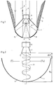
- FIG. 1 there is shown schematically an acoustic radar antenna 1 consisting of a parabloid surface 2 extended by a hood 3 internally covered with an acoustic absorbing material 4.
- a transmitting chamber 6, such as 'A compression chamber, extended by a horn 7 is held in the axis 5 of this antenna 1 which it is made integral by a rigid link 8 such as a tripod.
- a theoretical brush of backscattered sound waves 9 determining the effective area 10 of the antenna 1; the sound waves generated by the emission chamber 6 theoretically follow the opposite path.
- the surface portion 11 located in the axis 5 of the paraboloid is partially masked by the presence of the transmission and reception system.
- Figure 3 is shown schematically the electronic device for adapting the antenna 1; the outlet plane 15 of the horn 7 being located at the focal point of the paraboloid, at the abscissa Xo, the emission frequency f is modified to compensate for the theoretical evolution of the structure of interference fringes as a function of the temperature.
- the restoration of the pressure belly 13 at the abscissa Xo causes a variation in frequency Af around the frequency fo such that:
- the different stages of the transformation of the indication of the temperature T into ° K given by the temperature probe 14 are symbolized by blocks 27.
- the temperature variation T is transformed in a conventional electronic circuit 27A into a voltage variation V which in turn is transformed into frequency variation f by a conventional voltage / frequency converter 27B.
- This frequency variation is processed in a microcomputer 27C which reacts at the level of the emission E by modifying the frequency and at the level of the reception R by modifying the filters, so that they are always centered on the frequency d 'program.
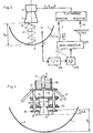
- FIG 4 is shown the mechanical adaptation system of the antenna 1 for moving the outlet plane 15 of the horn according to the theoretical law of evolution of - - structure of interference fringes as a function of temperature.
- This mechanical system comprises a hydraulic cylinder 16 disposed in the axis 5 of the paraboloide 2 and supported by a fixed plate 17.
- the end 18 of the rod 19 of this cylinder 16 is integral with an assembly 20 movable in the axis 5 of the paraboloid and comprising the emission chamber 6 extended by the horn 7, the assembly being supported by a frame consisting of two parallel plates 21 and 22 sliding along columns or vertical guides 23 supported by the fixed plate 17 rigidly connected to the structure of the dish 2 by the tripod system 8.
- the columns 23 are secured at their lower part by a plate 24 pierced with a circular opening 25 leaving free passage to the moving element 20.
- the capacity of the hydraulic jack 16 communicates with a coil 26 made of copper or any other good conductive material heat, which then constitutes the temperature probe shown diagrammatically at 14 in FIG. 3.
- the total capacity of 16 and 26 is such that, for a variation ⁇ T of the temperature at the level of the horn 7, the rod 19 of the jack 16 moves the desired length:
- the mechanical device for implementing the method is not limited to the embodiment of FIG. 4 and it could in particular be produced by a system of articulated arms taking, for example, support on the tripod 8, in the manner of a umbrella mechanism where the whales would be fixed.
Landscapes
- Physics & Mathematics (AREA)
- Engineering & Computer Science (AREA)
- Acoustics & Sound (AREA)
- Multimedia (AREA)
- Aerials With Secondary Devices (AREA)
- Measurement Of Velocity Or Position Using Acoustic Or Ultrasonic Waves (AREA)
- Radar Systems Or Details Thereof (AREA)
- Transducers For Ultrasonic Waves (AREA)
- Details Of Aerials (AREA)
Priority Applications (1)
| Application Number | Priority Date | Filing Date | Title |
|---|---|---|---|
| AT80401870T ATE4074T1 (de) | 1979-12-27 | 1980-12-24 | Verfahren zur anpassung einer akustischen radarantenne und vorrichtung zu ihrem betrieb. |
Applications Claiming Priority (2)
| Application Number | Priority Date | Filing Date | Title |
|---|---|---|---|
| FR7931740A FR2472803A1 (fr) | 1979-12-27 | 1979-12-27 | Procede d'adaptation des antennes d'un radar acoustique et dispositif pour la mise en oeuvre de ce procede |
| FR7931740 | 1979-12-27 |
Publications (2)
| Publication Number | Publication Date |
|---|---|
| EP0032095A1 EP0032095A1 (fr) | 1981-07-15 |
| EP0032095B1 true EP0032095B1 (fr) | 1983-07-06 |
Family
ID=9233182
Family Applications (1)
| Application Number | Title | Priority Date | Filing Date |
|---|---|---|---|
| EP80401870A Expired EP0032095B1 (fr) | 1979-12-27 | 1980-12-24 | Procédé d'adaptation d'une antenne de radar acoustique et dispositif pour sa mise en oeuvre |
Country Status (6)
| Country | Link |
|---|---|
| US (1) | US4358835A (enExample) |
| EP (1) | EP0032095B1 (enExample) |
| JP (1) | JPS5694284A (enExample) |
| AT (1) | ATE4074T1 (enExample) |
| DE (1) | DE3064059D1 (enExample) |
| FR (1) | FR2472803A1 (enExample) |
Families Citing this family (11)
| Publication number | Priority date | Publication date | Assignee | Title |
|---|---|---|---|---|
| US4632213A (en) * | 1983-02-28 | 1986-12-30 | Standard Oil Company (Indiana) | Seismic source system for use in water covered area |
| US4596006A (en) * | 1984-03-16 | 1986-06-17 | Honeywell Inc. | Ultrasonic object detector |
| US4719605A (en) * | 1984-12-13 | 1988-01-12 | Honeywell Inc. | Self-calibrating ultrasonic range finder |
| US4679175A (en) * | 1984-12-13 | 1987-07-07 | Honeywell Inc. | Ultrasonic distance sensor with dual burst noise rejection |
| DE3905099C1 (enExample) * | 1989-02-20 | 1990-08-09 | Schoeller Transportautomation Gmbh, 5120 Herzogenrath, De | |
| CA2046952C (en) * | 1990-07-13 | 2002-01-29 | Jeffrey James Felice | Measuring device |
| DE4435156C2 (de) * | 1994-09-30 | 2002-06-27 | Microsonic Ges Fuer Mikroelekt | Ultraschallsensor |
| CN2812027Y (zh) * | 2005-07-08 | 2006-08-30 | 南京德朔实业有限公司 | 超声波测距仪 |
| CN102196340A (zh) * | 2010-03-16 | 2011-09-21 | 鸿富锦精密工业(深圳)有限公司 | 集音式扬声器 |
| JP5755993B2 (ja) * | 2011-10-21 | 2015-07-29 | 理想科学工業株式会社 | 超音波センサ |
| CN112367468B (zh) * | 2020-10-30 | 2022-02-01 | 维沃移动通信有限公司 | 图像处理方法、装置及电子设备 |
Family Cites Families (2)
| Publication number | Priority date | Publication date | Assignee | Title |
|---|---|---|---|---|
| US2274262A (en) * | 1939-05-31 | 1942-02-24 | Rca Corp | Air speed indicator |
| US3895188A (en) * | 1972-06-21 | 1975-07-15 | Everett L Ingraham | Sound collecting device |
-
1979
- 1979-12-27 FR FR7931740A patent/FR2472803A1/fr active Granted
-
1980
- 1980-12-22 US US06/218,827 patent/US4358835A/en not_active Expired - Fee Related
- 1980-12-24 EP EP80401870A patent/EP0032095B1/fr not_active Expired
- 1980-12-24 AT AT80401870T patent/ATE4074T1/de active
- 1980-12-24 DE DE8080401870T patent/DE3064059D1/de not_active Expired
- 1980-12-26 JP JP18414780A patent/JPS5694284A/ja active Granted
Also Published As
| Publication number | Publication date |
|---|---|
| JPS6411152B2 (enExample) | 1989-02-23 |
| ATE4074T1 (de) | 1983-07-15 |
| US4358835A (en) | 1982-11-09 |
| FR2472803A1 (fr) | 1981-07-03 |
| EP0032095A1 (fr) | 1981-07-15 |
| JPS5694284A (en) | 1981-07-30 |
| FR2472803B1 (enExample) | 1984-07-06 |
| DE3064059D1 (en) | 1983-08-11 |
Similar Documents
| Publication | Publication Date | Title |
|---|---|---|
| EP0032095B1 (fr) | Procédé d'adaptation d'une antenne de radar acoustique et dispositif pour sa mise en oeuvre | |
| EP0267823B1 (fr) | Dispositif de détection de la présence de givre et/ou de mesure de l'épaisseur de givre par ultra-sons et sonde de givrage utilisable dans un tel dispositif | |
| EP0247908B1 (fr) | Capteur de niveau de liquide à ondes élastiques guidées | |
| FR2722566A1 (fr) | Capteur dynamique de deplacement, utilisations d'un tel capteur et procede de mesure du deplacement d'une surface | |
| FR2473721A1 (fr) | Dispositif a ultrasons pour l'indication de la presence de verglas sur une route asphaltee ou analogue | |
| WO2019091705A1 (fr) | Contrôle de sante d'une structure industrielle | |
| EP0942293B1 (fr) | Dispositif de mesure de distances ou de l'angle d'incidence d'un faisceau lumineux | |
| FR2836998A1 (fr) | Controle de puissance pour des systemes radar | |
| CH467998A (fr) | Dispositif à ultra-sons pour la mesure de la position d'un niveau liquide | |
| EP0480980B1 (fr) | Procede et dispositif de mesure de la gelification de produits petroliers paraffiniques, notamment bruts | |
| CA2140102A1 (fr) | Procede et capteur de mesure de la concentration en eau liquide dans un gaz en mouvement | |
| FR2868970A1 (fr) | Dispositif acoustique, sonde de jaugeage de liquide equipee d'un tel dispositif et systeme de jaugeage de liquide pourvu d'une telle sonde | |
| FR2661002A1 (fr) | Procede de detection par ultrasons et appareil de mesure pour sa mise en óoeuvre. | |
| CA2064372C (fr) | Dispositif de mesure en continu et sans contact de l'epaisseur d'une mince couche conductrice sur un support isolant, du genre fibre ou ruban, qui defile | |
| WO1998019133A1 (fr) | Dispositif de controle dimensionnel sans contact ultrasonore | |
| RU2175139C1 (ru) | Способ радиолокации пассивных космических объектов | |
| EP0508888B1 (fr) | Méthode de sélection de traducteurs ultrasonores | |
| Elias et al. | Detection of melting in release for a shock-loaded tin sample using the reflectivity measurement method | |
| RECOQUILLAY et al. | Optical fiber sensors for acoustic emission monitoring | |
| CA2133473A1 (fr) | Procede et dispositif de mesure d'epaisseur par ultra-sons et utilisation d'un tel dispositif | |
| SU853524A1 (ru) | Дефектоскоп | |
| EP0893702B1 (fr) | Récepteur destiné à l'acquisition de signaux radioélectriques, notamment de signaux émis par des satellites | |
| EP1014086B1 (fr) | Procédé et installation de mesure d'atténuation ultrasonore pour le contrôle non destructif par ultrasons laser | |
| SU1730569A1 (ru) | Измерительна секци | |
| FR3154187A1 (fr) | Procede de determination d’un gain d’un transducteur acoustique |
Legal Events
| Date | Code | Title | Description |
|---|---|---|---|
| PUAI | Public reference made under article 153(3) epc to a published international application that has entered the european phase |
Free format text: ORIGINAL CODE: 0009012 |
|
| AK | Designated contracting states |
Designated state(s): AT BE CH DE FR GB IT LU NL SE |
|
| 17P | Request for examination filed |
Effective date: 19811214 |
|
| ITF | It: translation for a ep patent filed | ||
| GRAA | (expected) grant |
Free format text: ORIGINAL CODE: 0009210 |
|
| AK | Designated contracting states |
Designated state(s): AT BE CH DE FR GB IT LI LU NL SE |
|
| REF | Corresponds to: |
Ref document number: 4074 Country of ref document: AT Date of ref document: 19830715 Kind code of ref document: T |
|
| REF | Corresponds to: |
Ref document number: 3064059 Country of ref document: DE Date of ref document: 19830811 |
|
| PLBE | No opposition filed within time limit |
Free format text: ORIGINAL CODE: 0009261 |
|
| STAA | Information on the status of an ep patent application or granted ep patent |
Free format text: STATUS: NO OPPOSITION FILED WITHIN TIME LIMIT |
|
| 26N | No opposition filed | ||
| PGFP | Annual fee paid to national office [announced via postgrant information from national office to epo] |
Ref country code: FR Payment date: 19921028 Year of fee payment: 13 |
|
| PGFP | Annual fee paid to national office [announced via postgrant information from national office to epo] |
Ref country code: AT Payment date: 19921126 Year of fee payment: 13 |
|
| PGFP | Annual fee paid to national office [announced via postgrant information from national office to epo] |
Ref country code: GB Payment date: 19921218 Year of fee payment: 13 |
|
| PGFP | Annual fee paid to national office [announced via postgrant information from national office to epo] |
Ref country code: SE Payment date: 19921222 Year of fee payment: 13 |
|
| PGFP | Annual fee paid to national office [announced via postgrant information from national office to epo] |
Ref country code: CH Payment date: 19921224 Year of fee payment: 13 |
|
| ITTA | It: last paid annual fee | ||
| PGFP | Annual fee paid to national office [announced via postgrant information from national office to epo] |
Ref country code: NL Payment date: 19921231 Year of fee payment: 13 |
|
| PGFP | Annual fee paid to national office [announced via postgrant information from national office to epo] |
Ref country code: DE Payment date: 19930113 Year of fee payment: 13 |
|
| PGFP | Annual fee paid to national office [announced via postgrant information from national office to epo] |
Ref country code: BE Payment date: 19930115 Year of fee payment: 13 |
|
| PGFP | Annual fee paid to national office [announced via postgrant information from national office to epo] |
Ref country code: LU Payment date: 19930120 Year of fee payment: 13 |
|
| EPTA | Lu: last paid annual fee | ||
| PG25 | Lapsed in a contracting state [announced via postgrant information from national office to epo] |
Ref country code: LU Free format text: LAPSE BECAUSE OF NON-PAYMENT OF DUE FEES Effective date: 19931224 Ref country code: GB Effective date: 19931224 Ref country code: AT Effective date: 19931224 |
|
| PG25 | Lapsed in a contracting state [announced via postgrant information from national office to epo] |
Ref country code: SE Effective date: 19931225 |
|
| PG25 | Lapsed in a contracting state [announced via postgrant information from national office to epo] |
Ref country code: LI Effective date: 19931231 Ref country code: CH Effective date: 19931231 Ref country code: BE Effective date: 19931231 |
|
| BERE | Be: lapsed |
Owner name: BERTIN & CIE Effective date: 19931231 |
|
| PG25 | Lapsed in a contracting state [announced via postgrant information from national office to epo] |
Ref country code: NL Effective date: 19940701 |
|
| NLV4 | Nl: lapsed or anulled due to non-payment of the annual fee | ||
| GBPC | Gb: european patent ceased through non-payment of renewal fee |
Effective date: 19931224 |
|
| PG25 | Lapsed in a contracting state [announced via postgrant information from national office to epo] |
Ref country code: FR Effective date: 19940831 |
|
| REG | Reference to a national code |
Ref country code: CH Ref legal event code: PL |
|
| PG25 | Lapsed in a contracting state [announced via postgrant information from national office to epo] |
Ref country code: DE Effective date: 19940901 |
|
| REG | Reference to a national code |
Ref country code: FR Ref legal event code: ST |
|
| EUG | Se: european patent has lapsed |
Ref document number: 80401870.3 Effective date: 19940710 |