EP0032091B1 - Contenant pour produits rigides tels que bâtonnets, mines de stylo et analogues - Google Patents
Contenant pour produits rigides tels que bâtonnets, mines de stylo et analogues Download PDFInfo
- Publication number
- EP0032091B1 EP0032091B1 EP80401845A EP80401845A EP0032091B1 EP 0032091 B1 EP0032091 B1 EP 0032091B1 EP 80401845 A EP80401845 A EP 80401845A EP 80401845 A EP80401845 A EP 80401845A EP 0032091 B1 EP0032091 B1 EP 0032091B1
- Authority
- EP
- European Patent Office
- Prior art keywords
- push button
- slot
- sliding block
- opening
- pusher
- Prior art date
- Legal status (The legal status is an assumption and is not a legal conclusion. Google has not performed a legal analysis and makes no representation as to the accuracy of the status listed.)
- Expired
Links
Images
Classifications
-
- A—HUMAN NECESSITIES
- A45—HAND OR TRAVELLING ARTICLES
- A45D—HAIRDRESSING OR SHAVING EQUIPMENT; EQUIPMENT FOR COSMETICS OR COSMETIC TREATMENTS, e.g. FOR MANICURING OR PEDICURING
- A45D40/00—Casings or accessories specially adapted for storing or handling solid or pasty toiletry or cosmetic substances, e.g. shaving soaps or lipsticks
- A45D40/02—Casings wherein movement of the lipstick or like solid is a sliding movement
- A45D40/023—Casings wherein movement of the lipstick or like solid is a sliding movement with self-contained covering means
- A45D40/026—Casings wherein movement of the lipstick or like solid is a sliding movement with self-contained covering means consisting of a movable strip
Definitions
- the present invention relates to a container of the type comprising an elongated body with an opening in the transverse end face for the passage of the content, a lumen along the longitudinal lateral side of said body, said lumen ending in said opening by a rounded part. and merging in the internal chamber of said body receiving the content, grooves forming guide means arranged in the lateral sides of said light and this on either side of the latter a flexible element sliding in said grooves forming the guide means the flexible element and fixed at one end, inside said internal chamber on the content which is slidingly guided in said chamber and at its other end on the actuating push button which can slide at outside the body, along said slit and above said opening so as to cover said opening.
- a container is described for example in FR-A-721.239.
- the function of the flexible strip which synchronizes only the movements of the push button and of the content is dissociated from the guiding function which is provided by a sliding block guided in an independent slide secured to the movement with the push button.
- the connection between this sliding block which follows an internal guide path and the push button which must be applied without play on the external surfaces of the container poses a problem in particular at the level of the connection curve between the lateral face and the end face in which is carried out the opening. This problem results from the fact that the sliding block subtends a cord of the arc of the internal guide while the push button is tangent to the external curved surface.
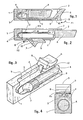
- Figures 1 to 4 show a lipstick case according to an embodiment which follows from the prior art
- Figures 1 and 2 are sectional views of the case respectively in the closed position and in the open position
- Figure 3 is a partial schematic perspective view of the same case
- Figure 4 is a sectional view
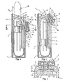
- Figures 5 and 6 show in axial section a container according to a first embodiment of the invention in two different positions of the pusher
- Figure 7 is a schematic view on a larger scale showing the association of the pusher, the shoe and the flexible element
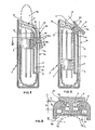
- Figures 8 and 9 show in axial section a container produced according to another embodiment of the invention
- FIG. 10 is a partial view made in section along the line X-X of FIG. 8.
- a container of the type concerned by the invention comprises, on the one hand, a body 1 with an opening 2 for the passage of the content A and, on the other hand, a flexible element 3 which slides in internal guides 4 of the body 1 in line with a light 5, which is fixed by one of its ends to a member 7 for extracting the content A and which is associated by its other end with an operating push button 6 which must be placed either opposite the light 5 to release the opening 2 either opposite said opening 2 to close it in the manner of a cover, the pusher-cover 6 being resiliently mounted relative to the guides 4 of the body 1.
- the pusher-seal 6 is resiliently mounted due to its connection with a part 8 formed by a section of the flexible element 3 which is itself elastic.
- the part 8, by which the valve member 6 is connected to the flexible element 3, is constituted by a section of this element 3 narrowed in order to be able to extend out of the lumen 5, between the edges of this last.
- the flexible element 3 which here consists of an elastic strip, can be very narrow, to give the guides 4 a small spacing and in any case less than the internal dimensions of the body 1.
- the cover constituted by the pusher 6 can be as wide as desired, if only for aesthetic reasons, because this pusher cover 6 moves outside the light 5 and also applies outside the opening 2.
- the pusher-seal 6 has a spout 9 located near its end adjacent to the flexible element 3 so that, by acting on this spout 9, the pusher-seal 6 is pivoted first , yes, then, its sliding along the light 5.
- the flexible element 3 being elastic, the camber along the angle 10 causes the energetic folding down of the valve lifter 6 as soon as it escapes the sides of the body 1, like the cover of a lighter for example.
- the pusher-lid 6 having to pivot and unmask the opening 2 before sliding, the end of the lipstick stick A can never touch the lid, even if it is longer than expected, since this length is compatible with the correct closing of the case.
- the body 1 can advantageously be obtained by the union of two similar parts (or "shells", only one is visible in FIG. 3) each obtained by molding in one piece of a synthetic material.
- the two shells are brought together after introduction of the flexible element 3 between the guides 4 and of the sleeve 7 in the center of the body 1.
- the flexible element 3 can be made integral on the one hand with the valve member 6 and on the other hand with the sleeve 7 by overmolding of these members as shown.
- Maintaining the pusher-seal 6 in place opposite the opening 2 can be obtained by providing a snap-fastening of any known type.
- the part 8 by which the pusher-seal 6 is connected to the flexible element 3 is constituted by a pad 6a secured to the pusher-seal 6, as can be seen in FIG. 4.
- the element 3 of the container has a constant width even in its part closest to the pusher 6 and that this part is freely crossed by a heel 11 of an inner shoe 12, this heel 11 being elastically connected to the pusher 6, to the vicinity of the central part of the latter.
- the shoe 12 is placed opposite a rib 13 parallel to the guides 4 of the flexible element 3 and is urged against this rib 13 by an elastic member such as a piano string 14 which passes through a passage 15 of the heel 11 and bears on two edges 16 of the pusher 6 substantially parallel to the plane of the element 3, so that the heel 11 and the pusher 6 can be elastically separated from one another and elastically stressed towards each other.
- an elastic member such as a piano string 14 which passes through a passage 15 of the heel 11 and bears on two edges 16 of the pusher 6 substantially parallel to the plane of the element 3, so that the heel 11 and the pusher 6 can be elastically separated from one another and elastically stressed towards each other.
- the pusher 6 is located in the rectilinear part of its course, that is to say below the connection curve between this rectilinear part and the plane of obturation of the opening 2.
- the thicknesses are calculated in such a way that the shoe 12 bears elastically against the rib 13 without excessive friction.
- the heel 11 passes through the flexible element 3 through a hole 3a of dimensions such that the heel 11 1 can pass through this element 3 while leaving it relatively free but, of course, the heel 11 is supported on one or the other. transverse sides of the hole 3a, in the direction in which one acts on the pusher 6.
- the piano cord 14 has a fairly weak action and the spacing X between the face of the pusher 6 which rests on the body 1 and the face of the shoe 12 which rests on the rib 13 is minimum.
- the shoe 12 must have a certain length which is placed along the cord relative to the arc of a circle of the rib 13 in its curved part. Therefore, the heel 11 must be able to enter the inside of the case while the pusher 6 remains against the body 1 and this over a length equal to the arrow corresponding to the rope and to the bow stated above, this which gives a spacing Y between the face of the pusher 6 applied against the body 1 and the face of the shoe 12 applied against the rib 13, this distance Y therefore being greater than the distance X.
- the pusher 6 is here characterized in that it has an outer face hollowed out in a bowl in order to constitute a housing for the heel 11 1 and for the piano string 14, a cover 17 being attached and held in place by any means known for conceal these members 11-14 and constitute a bearing surface for the operation of the entire pusher 6.
- the means for holding in place the cover 17 are constituted by hooks 18 and 19 placed on either side of the piano string 14 to ensure the proper retention of this last.
- the hooks 18 and 19 have substantially the shape of harpoons and are elastically deformable because they consist of a single piece with the cover 17 of synthetic material. They are engaged in the space which separates the two edges 16 so that after having found their original position, their harpoon-shaped ends are found under the sides adjacent to the edges 16.
- the piano cord 14 having a certain length unlike the upper part of the heel 11 which is relatively thin, it could happen that the piano cord moves obliquely then ends up leaving the position which must be its own.
- the pusher 6 being guided positively to its extreme position for closing the opening 2, it is suitably applied and held in place.
- the movable assembly connected to the flexible element 3, namely pous- either 6- pad 12 is mini means capable of cooperating with a member integral with the body 1 to immobilize elastically this mobile assembly in the closed position of the opening 2.
- These means can consist of a tongue and the member secured to the body 1 in a small housing located at the end of the path of the pusher 6.
- the means with which the mobile assembly is provided are constituted by lateral bosses 20 which have to cooperate with notches 21 situated on the sides of the opening 2.
- the bosses 20 have a rounded profile, as do the notches 21, so that their cooperation and separation occur smoothly.
- the entry of the bosses 20 into the notches 21 causes a real snap-fastening due to the fact that the piano wire 14 permanently biases the shoe 12 towards the rib 13 and therefore in the direction of the notches 21 provided in this rib 13.
- the exit of the bosses 20 outside the notches 21 is therefore done in reverse by stressing the piano string 14.
- the pusher 6 is thus vigorously applied to the top of the body 1 and ensures that the opening 2 is closed sufficiently tight to oppose the entry of the dust. This pusher is therefore both held opposite the opening 3 and applied to its edges.
- the valve lifter 6 is resiliently mounted due to the constitution of a flexible material at least of its heel 6a and of a pad 6b which is integral with the heel 6a and which bears on a rib 13, this pad 6b preferably being arched to present a convexity directed towards the heel 6a according to a curvature such that the distance x which extends from the points of support of the shoe 6c against the rib 13 to the pusher-seal 6 is substantially equal to the distance which separates the rib 13 from the external face 1a of the body 1 on which the cover push-button 6 must be supported.
- the shoe 6b has edges 6c which are substantially transverse to the axis of the rib 13 and which are rounded.
- lateral bosses 20 having to cooperate with notches 21 situated on the sides of the opening 2 are provided near one of the rounded edges 6c, on the convex face of the shoe 6b.
- valve member 6, the heel 6a and the shoe 6b are obtained by molding in a single piece, also makes it possible to produce in a single piece with these elements the flexible element 3 and possibly the extraction member 7 of content A.
- the entire container is then summed up in three parts: two half-shells constituting, by gluing, the body 1 and a single part comprising the flexible element 3, the member 7 and the pusher-seal 6.
- the material chosen for molding must be flexible enough to be elastic but must have "nerve” so as not to lose, over time, its capacity for permanent elastic stress.
Landscapes
- Closures For Containers (AREA)
- Pens And Brushes (AREA)
- Mechanical Pencils And Projecting And Retracting Systems Therefor, And Multi-System Writing Instruments (AREA)
- Holders For Apparel And Elements Relating To Apparel (AREA)
- Containers And Packaging Bodies Having A Special Means To Remove Contents (AREA)
Priority Applications (1)
| Application Number | Priority Date | Filing Date | Title |
|---|---|---|---|
| AT80401845T ATE10900T1 (de) | 1979-12-27 | 1980-12-23 | Behaelter fuer steife produkte, wie z.b. staebchen, bleistiftminen und dgl. |
Applications Claiming Priority (4)
| Application Number | Priority Date | Filing Date | Title |
|---|---|---|---|
| FR7931727A FR2472520A1 (fr) | 1979-12-27 | 1979-12-27 | Contenant pour produits rigides tels que batonnets, mines de stylo et analogues |
| FR7931727 | 1979-12-27 | ||
| FR8019813 | 1980-09-15 | ||
| FR8019813A FR2490193A2 (fr) | 1980-09-15 | 1980-09-15 | Contenant pour produits rigides tels que batonnets, mines de stylo et analogues |
Publications (3)
| Publication Number | Publication Date |
|---|---|
| EP0032091A2 EP0032091A2 (fr) | 1981-07-15 |
| EP0032091A3 EP0032091A3 (en) | 1981-07-29 |
| EP0032091B1 true EP0032091B1 (fr) | 1984-12-27 |
Family
ID=26221512
Family Applications (1)
| Application Number | Title | Priority Date | Filing Date |
|---|---|---|---|
| EP80401845A Expired EP0032091B1 (fr) | 1979-12-27 | 1980-12-23 | Contenant pour produits rigides tels que bâtonnets, mines de stylo et analogues |
Country Status (13)
| Country | Link |
|---|---|
| US (1) | US4367965A (es) |
| EP (1) | EP0032091B1 (es) |
| AR (1) | AR229507A1 (es) |
| AU (1) | AU538881B2 (es) |
| BR (1) | BR8008543A (es) |
| CA (1) | CA1147296A (es) |
| DE (1) | DE3069885D1 (es) |
| DK (1) | DK544380A (es) |
| ES (1) | ES267087Y (es) |
| GR (1) | GR72811B (es) |
| IL (1) | IL61811A (es) |
| PT (1) | PT72286B (es) |
| YU (1) | YU322380A (es) |
Families Citing this family (28)
| Publication number | Priority date | Publication date | Assignee | Title |
|---|---|---|---|---|
| CH656513A5 (de) * | 1982-08-23 | 1986-07-15 | Kolmar Cosmetics Europ | Stabfoermige dispensiervorrichtung. |
| JPS6422487U (es) * | 1987-08-03 | 1989-02-06 | ||
| US4817526A (en) * | 1987-10-22 | 1989-04-04 | Winston Jeffrey M | Rolling contact printer with retractable inking wheel |
| IT1238392B (it) * | 1990-02-13 | 1993-07-16 | Contenitore per rossetto,pasta per labbra e/o deodorante con coperturamobile inclinata | |
| FR2715543B1 (fr) * | 1994-02-01 | 1996-04-19 | Daniel Robert Benguigui | Etui pour bâton de produits, notamment cosmétiques ou pharmaceutiques et procédé d'assemblage de cet étui. |
| US5505130A (en) * | 1994-06-10 | 1996-04-09 | Winston; Jeffrey M. | Ink pad assemblies with interchangeable ink-impregnated pads |
| US5870953A (en) * | 1994-06-10 | 1999-02-16 | Winston; Jeffrey M. | Ink pad assemblies with interchangeable ink-impregnated pads |
| JP2905144B2 (ja) * | 1995-09-14 | 1999-06-14 | 有限会社野々川商事 | 棒状化粧料容器 |
| GB9607407D0 (en) | 1996-04-10 | 1996-06-12 | Parker Pen Products | Refillable reservoir eg for ink |
| US5984551A (en) * | 1997-04-25 | 1999-11-16 | Kinney, Jr.; George C. | Dispenser of solids and semi-solids |
| DE19856491C2 (de) * | 1998-12-08 | 2001-11-15 | Harter Karl Friedrich | Behälter zur Bevorratung von Gegenständen |
| WO2001008530A1 (en) | 1999-07-29 | 2001-02-08 | The Bridgeport Metal Goods Manufacturing Company | Cosmetics container and applicator for one hand operation |
| US6237613B1 (en) | 1999-09-02 | 2001-05-29 | Owens-Illinois Closure Inc. | Two-piece cosmetic applicator |
| US6371129B1 (en) * | 2000-02-18 | 2002-04-16 | Revlon Consumer Products Corporation | Dispenser for fluid materials |
| GB0028362D0 (en) * | 2000-11-21 | 2001-01-03 | Optoplast Plc | Improvements in cases for personal accessories |
| US6902333B2 (en) * | 2001-06-22 | 2005-06-07 | M·F·V Co., Ltd. | Container capable of moving a contained article in longitudinal direction |
| US7597250B2 (en) | 2003-11-17 | 2009-10-06 | Dpd Patent Trust Ltd. | RFID reader with multiple interfaces |
| US7762470B2 (en) | 2003-11-17 | 2010-07-27 | Dpd Patent Trust Ltd. | RFID token with multiple interface controller |
| US7213766B2 (en) * | 2003-11-17 | 2007-05-08 | Dpd Patent Trust Ltd | Multi-interface compact personal token apparatus and methods of use |
| US7194954B2 (en) * | 2004-02-10 | 2007-03-27 | Clearsnap Holding, Inc. | Continuous ink stamping systems and methods |
| AU2005200577B8 (en) * | 2004-02-10 | 2011-01-20 | Clearsnap Holding, Inc. | Continuous material processing systems and methods for arts and crafts |
| FR2866600B1 (fr) * | 2004-02-23 | 2008-04-04 | Bic Soc | Instrument d'ecriture |
| US20060037503A1 (en) * | 2004-08-23 | 2006-02-23 | Winston Jeffrey M | Roller press systems and methods |
| US7748636B2 (en) * | 2004-11-16 | 2010-07-06 | Dpd Patent Trust Ltd. | Portable identity card reader system for physical and logical access |
| DE202006018230U1 (de) * | 2006-11-30 | 2008-04-10 | Stabilo International Gmbh | Stift |
| US7963221B2 (en) * | 2008-03-19 | 2011-06-21 | Clearsnap Holding, Inc. | Systems and methods for forming continuous ink images |
| US20100326298A1 (en) * | 2009-06-30 | 2010-12-30 | Clearsnap Holding, Inc. | Continuous ink stamping systems and methods with reconfigurable stamping assembly |
| KR200478730Y1 (ko) * | 2014-05-09 | 2015-11-11 | (주)아모레퍼시픽 | 슬라이드 타입의 립스틱 용기 |
Family Cites Families (11)
| Publication number | Priority date | Publication date | Assignee | Title |
|---|---|---|---|---|
| FR663721A (fr) * | 1928-11-09 | 1929-08-24 | étui pour fard ou toutes autres applications | |
| US1776098A (en) * | 1930-02-14 | 1930-09-16 | Barbas Raymond | Sheath crayon holder |
| FR721239A (fr) * | 1931-08-11 | 1932-03-01 | étui manceuvrable d'une seule main | |
| US2118399A (en) * | 1934-10-31 | 1938-05-24 | Bridgeport Metal Goods Mfg Co | Cosmetic holder |
| US2402072A (en) * | 1944-06-07 | 1946-06-11 | Revlon Products Corp | Case for lipstick and the like |
| US2453250A (en) * | 1945-08-14 | 1948-11-09 | Nehrke Charles | Lipstick container |
| FR933926A (fr) * | 1946-09-19 | 1948-05-05 | étui pour tous produits présentés en bâtons | |
| FR1408868A (fr) * | 1964-07-08 | 1965-08-20 | étui à ouverture combinée avec extraction du contenu | |
| FR1491052A (fr) * | 1966-09-01 | 1967-08-04 | Boîtier obturable pour article de poche ou de sac | |
| US3810700A (en) * | 1972-01-12 | 1974-05-14 | J Bryan | Slide closure cosmetic stick dispenser casing |
| US3941489A (en) * | 1974-03-22 | 1976-03-02 | Vca Corporation | Flat top one-hand cylindrical lipstick case |
-
1980
- 1980-12-19 DK DK544380A patent/DK544380A/da not_active Application Discontinuation
- 1980-12-19 YU YU03223/80A patent/YU322380A/xx unknown
- 1980-12-22 ES ES1980267087U patent/ES267087Y/es not_active Expired
- 1980-12-23 EP EP80401845A patent/EP0032091B1/fr not_active Expired
- 1980-12-23 DE DE8080401845T patent/DE3069885D1/de not_active Expired
- 1980-12-23 PT PT72286A patent/PT72286B/pt unknown
- 1980-12-24 CA CA000367537A patent/CA1147296A/fr not_active Expired
- 1980-12-24 AU AU65832/80A patent/AU538881B2/en not_active Expired - Fee Related
- 1980-12-26 AR AR283803A patent/AR229507A1/es active
- 1980-12-26 IL IL61811A patent/IL61811A/xx unknown
- 1980-12-27 GR GR63763A patent/GR72811B/el unknown
- 1980-12-29 US US06/221,012 patent/US4367965A/en not_active Expired - Fee Related
- 1980-12-29 BR BR8008543A patent/BR8008543A/pt unknown
Also Published As
| Publication number | Publication date |
|---|---|
| EP0032091A3 (en) | 1981-07-29 |
| ES267087U (es) | 1983-08-01 |
| CA1147296A (fr) | 1983-05-31 |
| IL61811A0 (en) | 1981-01-30 |
| US4367965A (en) | 1983-01-11 |
| PT72286B (fr) | 1982-02-10 |
| BR8008543A (pt) | 1981-07-21 |
| ES267087Y (es) | 1984-12-01 |
| IL61811A (en) | 1984-01-31 |
| DK544380A (da) | 1981-06-28 |
| AU538881B2 (en) | 1984-08-30 |
| AU6583280A (en) | 1981-07-02 |
| PT72286A (fr) | 1981-01-01 |
| YU322380A (en) | 1983-02-28 |
| DE3069885D1 (en) | 1985-02-07 |
| AR229507A1 (es) | 1983-09-15 |
| GR72811B (es) | 1983-12-05 |
| EP0032091A2 (fr) | 1981-07-15 |
Similar Documents
| Publication | Publication Date | Title |
|---|---|---|
| EP0032091B1 (fr) | Contenant pour produits rigides tels que bâtonnets, mines de stylo et analogues | |
| EP0847710B1 (fr) | Articulation a ressort pour article de chevelure | |
| FR2923810A1 (fr) | Tete de distribution du type a declenchement par gachette. | |
| EP2935037B1 (fr) | Systeme de recouvrement escamotable et ensemble de conditionnement et d'application de produit equipe d'un tel systeme | |
| FR2923811A1 (fr) | Recipient equipe d'un dispositif de securite. | |
| CH636529A5 (fr) | Fixation de securite de ski. | |
| EP0467761B1 (fr) | Boîtier muni d'un fermoir monopièce | |
| FR2576537A1 (fr) | Fourreau aiguiseur et sa combinaison avec un couteau | |
| EP0661938B1 (fr) | Fermoir du type a boucle deployante pour bracelet | |
| EP0547978A1 (fr) | Capsule de distribution pour un produit fluide ou visqueux et récipient équipé d'une telle capsule | |
| FR2751516A1 (fr) | Fermoir a boucle deployante | |
| FR2515079A1 (fr) | Dispositif pour le moulage par compression d'une cage de roulement | |
| FR2651145A1 (fr) | Fixation de securite pour ski. | |
| FR2605981A1 (fr) | Boite pour cosmetique | |
| FR2588794A1 (fr) | Agrafeuse du type a cassette | |
| CH627408A5 (fr) | Stylos a recharge a encre. | |
| FR2553272A1 (fr) | Dispositif de securite pour portefeuille ou analogue | |
| EP0664976A1 (fr) | Etui pour bâton de produits, notamment cosmétiques ou pharmaceutiques et procédé d'assemblage de cet étui | |
| FR3108483A1 (fr) | Réceptacle d’un produit cosmétique et recharge pour un tel réceptacle | |
| EP1582315A1 (fr) | Ciseaux à ressort d'ouverture | |
| EP3897273B1 (fr) | Fermoir a boucle deployante pour bracelet | |
| FR2708437A1 (fr) | Etui pour bâton de produit pâteux cosmétique, pharmaceutique ou analogue. | |
| FR2490193A2 (fr) | Contenant pour produits rigides tels que batonnets, mines de stylo et analogues | |
| EP0867132B1 (fr) | Fermoir de type automatique notamment pour bracelet-montre | |
| FR2682858A1 (fr) | Chausson interne pour chaussure de ski alpin. |
Legal Events
| Date | Code | Title | Description |
|---|---|---|---|
| PUAI | Public reference made under article 153(3) epc to a published international application that has entered the european phase |
Free format text: ORIGINAL CODE: 0009012 |
|
| PUAL | Search report despatched |
Free format text: ORIGINAL CODE: 0009013 |
|
| AK | Designated contracting states |
Designated state(s): AT BE CH DE GB IT LU NL SE |
|
| AK | Designated contracting states |
Designated state(s): AT BE CH DE GB IT LU NL SE |
|
| 17P | Request for examination filed |
Effective date: 19810916 |
|
| GRAA | (expected) grant |
Free format text: ORIGINAL CODE: 0009210 |
|
| AK | Designated contracting states |
Designated state(s): AT BE CH DE GB IT LI LU NL SE |
|
| PG25 | Lapsed in a contracting state [announced via postgrant information from national office to epo] |
Ref country code: SE Effective date: 19841227 Ref country code: NL Effective date: 19841227 Ref country code: IT Free format text: LAPSE BECAUSE OF FAILURE TO SUBMIT A TRANSLATION OF THE DESCRIPTION OR TO PAY THE FEE WITHIN THE PRESCRIBED TIME-LIMIT;WARNING: LAPSES OF ITALIAN PATENTS WITH EFFECTIVE DATE BEFORE 2007 MAY HAVE OCCURRED AT ANY TIME BEFORE 2007. THE CORRECT EFFECTIVE DATE MAY BE DIFFERENT FROM THE ONE RECORDED. Effective date: 19841227 Ref country code: AT Effective date: 19841227 |
|
| REF | Corresponds to: |
Ref document number: 10900 Country of ref document: AT Date of ref document: 19850115 Kind code of ref document: T |
|
| REF | Corresponds to: |
Ref document number: 3069885 Country of ref document: DE Date of ref document: 19850207 |
|
| NLV1 | Nl: lapsed or annulled due to failure to fulfill the requirements of art. 29p and 29m of the patents act | ||
| PLBE | No opposition filed within time limit |
Free format text: ORIGINAL CODE: 0009261 |
|
| STAA | Information on the status of an ep patent application or granted ep patent |
Free format text: STATUS: NO OPPOSITION FILED WITHIN TIME LIMIT |
|
| PG25 | Lapsed in a contracting state [announced via postgrant information from national office to epo] |
Ref country code: LU Free format text: LAPSE BECAUSE OF NON-PAYMENT OF DUE FEES Effective date: 19851231 |
|
| 26N | No opposition filed | ||
| PGFP | Annual fee paid to national office [announced via postgrant information from national office to epo] |
Ref country code: BE Payment date: 19890111 Year of fee payment: 9 |
|
| PGFP | Annual fee paid to national office [announced via postgrant information from national office to epo] |
Ref country code: DE Payment date: 19890207 Year of fee payment: 9 |
|
| REG | Reference to a national code |
Ref country code: CH Ref legal event code: PFA Free format text: TECHPACK INTERNATIONAL |
|
| PG25 | Lapsed in a contracting state [announced via postgrant information from national office to epo] |
Ref country code: GB Effective date: 19891223 |
|
| PG25 | Lapsed in a contracting state [announced via postgrant information from national office to epo] |
Ref country code: LI Effective date: 19891231 Ref country code: CH Effective date: 19891231 Ref country code: BE Effective date: 19891231 |
|
| BERE | Be: lapsed |
Owner name: TECHPACK INTERNATIONAL Effective date: 19891231 |
|
| GBPC | Gb: european patent ceased through non-payment of renewal fee | ||
| REG | Reference to a national code |
Ref country code: CH Ref legal event code: PL |
|
| PG25 | Lapsed in a contracting state [announced via postgrant information from national office to epo] |
Ref country code: DE Effective date: 19900901 |