EP0032083A1 - Dispositifs de connexion électrique et d'essai - Google Patents
Dispositifs de connexion électrique et d'essai Download PDFInfo
- Publication number
- EP0032083A1 EP0032083A1 EP80401790A EP80401790A EP0032083A1 EP 0032083 A1 EP0032083 A1 EP 0032083A1 EP 80401790 A EP80401790 A EP 80401790A EP 80401790 A EP80401790 A EP 80401790A EP 0032083 A1 EP0032083 A1 EP 0032083A1
- Authority
- EP
- European Patent Office
- Prior art keywords
- connection
- pair
- elements
- members
- test
- Prior art date
- Legal status (The legal status is an assumption and is not a legal conclusion. Google has not performed a legal analysis and makes no representation as to the accuracy of the status listed.)
- Withdrawn
Links
Images


Classifications
-
- G—PHYSICS
- G01—MEASURING; TESTING
- G01R—MEASURING ELECTRIC VARIABLES; MEASURING MAGNETIC VARIABLES
- G01R1/00—Details of instruments or arrangements of the types included in groups G01R5/00 - G01R13/00 and G01R31/00
- G01R1/02—General constructional details
- G01R1/04—Housings; Supporting members; Arrangements of terminals
- G01R1/0408—Test fixtures or contact fields; Connectors or connecting adaptors; Test clips; Test sockets
-
- H—ELECTRICITY
- H01—ELECTRIC ELEMENTS
- H01R—ELECTRICALLY-CONDUCTIVE CONNECTIONS; STRUCTURAL ASSOCIATIONS OF A PLURALITY OF MUTUALLY-INSULATED ELECTRICAL CONNECTING ELEMENTS; COUPLING DEVICES; CURRENT COLLECTORS
- H01R29/00—Coupling parts for selective co-operation with a counterpart in different ways to establish different circuits, e.g. for voltage selection, for series-parallel selection, programmable connectors
-
- H—ELECTRICITY
- H01—ELECTRIC ELEMENTS
- H01R—ELECTRICALLY-CONDUCTIVE CONNECTIONS; STRUCTURAL ASSOCIATIONS OF A PLURALITY OF MUTUALLY-INSULATED ELECTRICAL CONNECTING ELEMENTS; COUPLING DEVICES; CURRENT COLLECTORS
- H01R31/00—Coupling parts supported only by co-operation with counterpart
- H01R31/08—Short-circuiting members for bridging contacts in a counterpart
Definitions
- the present invention relates to electrical connection and testing devices, for example to allow the verification of electrical equipment such as protection relays.
- protection relays of various kinds are used in electrical energy distribution networks to detect faults and avoid damaging the network by quickly taking the necessary measures.
- the operation of such relays often involves monitoring the current or currents measured in the network at the location of the relay, and for this purpose the relay is generally connected to the network using devices known as transformers. current.
- transformers. current In order to ensure the reliability of a protection relay system, it is necessary to regularly test each relay by applying test signals representative of different possible fault conditions. During these tests, the relay is generally disconnected from its associated current transformer, but the latter remains connected to the live network.
- a short-circuit bar stressed by a spring maintains continuity between each connection terminal of the current transformer and the respective terminal of the relay circuit until a test socket is inserted.
- the actual test socket comprises insulated connection members to the terminals of which a short-circuiting load should be connected to the terminals of the current transformer so that the integrity of the output circuits of this transformer always depends on correct assembly of the test circuit and is subject to human error.
- a direct short circuit is automatically established inside the test box between the output members of the current transformer when the test socket is inserted, but the output circuit of the transformer remains completely inaccessible inside the test equipment when it would be desirable to have access to it to carry out certain checks and adjustments by interposing other equipment with the appropriate precautions.
- a test socket for an electrical connection device in which a first element has a first pair of members for connection to a current transformer and a second pair of members for connection to an operating circuit operating in response to this current transformer, each of the connection members of the first pair being connected to a corresponding connection member of the second pair by a respective interruptible link
- this test socket comprising a second element having a first and a second pair of ageneated connection members for coming into contact respectively with said first and second pair of connection elements of the first element when said elements are coupled in operation, and means for operating said interruptible link
- this socket being further characterized in that it comprises connection means forming an integral part of said second element and connected to the first pair of connection members thereof so as to electrically connect them to each other at least when said first and second elements are coupled; and in that, when said elements are progressively coupled, the first pairs of connection members of each of these elements first come into reciprocal contact in order to establish via said connection means a continuous circuit including said transformer current; then said maneuvering means
- the invention also relates to a device for connection of an electrical apparatus to a network adapted to be functionally coupled with a test socket of the type defined above.
- connection and test equipment which will now be described is intended for use with a protection relay monitoring input signals from current transformers and voltage transformers connected to an energy distribution network electric polyphase to provide output signals for the eventual control of a circuit breaker.
- a protection relay monitoring input signals from current transformers and voltage transformers connected to an energy distribution network electric polyphase to provide output signals for the eventual control of a circuit breaker.
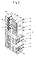
- connection and test box is generally designated by the reference 10, and comprises a molded plastic body 12 in which are mounted a plurality (for example 32 ) of sleeves or sockets of female electrical connectors 14. These sockets 14 are grouped in vertical pairs, a vertical line formed by four pairs such as 14A-14B, 14C-14D, 14E-14F, 14G-14H, being associated with the one of the phases of the network.
- the two upper pairs 14A-14B and 14C-14D are associated with a current transformer 40 (see FIG. 4) connected to a respective phase conductor 42, the pair immediately below, 14E-14F, is associated with a capacitive voltage transformer 44 connected to conductor 12, and the lowest pair 14G-14H is associated with an output circuit of the protection relay designated by the reference 46.
- each short-circuit element 16 has at its rear part a portion 22 equipped with a self-tapping screw (see FIG. 4) by means of which the element 16 can be secured at will to the body 12 by rotating the portion 22 using a screwdriver engaged in a slot at its front part.
- the elements 16c and 16d associated with the pairs of sockets 14E-14F and 14G-14H, are thus immobilized and inactive in the example described while the two upper elements 16a and 16b are not.
- a short-circuit connection 24 comprising two sockets 26 coupled by a plate 28.
- a neutral plug 30 is simply provided or, alternatively, the corresponding cavity can be left open.
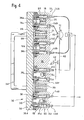
- the terminals S1 and S2 of the secondary winding of the current transformer 40 are connected to the sockets 1 4 B and 14C respectively, while the associated input terminals of the relay 46 are connected to the sockets 14A and 14B.
- the output terminal of the capacitive voltage transformer 44 is connected to the socket 14F and the associated input terminal of the relay 46 is connected to the socket 14E.
- the output terminal of the relay 46 is connected to the socket 14H and the circuit breaker or other equipment intended to process the output signal of the relay is connected to the socket 14G.
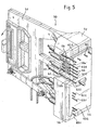
- the housing 10 When protection relay 46 is in operation normal, the housing 10 is closed by a cover 30, shown in FIG. 3.
- the cover 30 comprises a plastic plate 32 provided with a handle 34 on its external face and 16 bridging pieces 36 on its internal face.
- Each bridging piece 36 has two end plugs 38 connected by a cross member 39 and the distance of which corresponds to that of the sockets 14 of each of the sixteen pairs of sockets 14 of the housing 12.
- each bridging piece 36 is in conductive contact with the sockets 14 of the respective pair.
- the secondary circuit of the current transformer 40 is completed between its terminals S1 and S2, by the socket 14B, the bridging piece 36a, (which is located in parallel with the shorting element 24), the socket 14A , the relay 46, the socket 14B, the bridging piece 36b and the socket 14C.
- the output terminal of the capacitive voltage transformer 44 is connected to the relay 46 via the socket 14F, the bridging piece 36c and the socket 14E and the output signal of the relay 46 is applied by the 'intermediate the socket 14H, the bridging piece 36d and the socket 14G.
- the cover 30 of the housing 10 is first removed. This has the effect in particular of interrupting the connections between the sockets 14E and 14F, and between the sockets 14G and 14H, by removing thus applying the voltage to relay 46 and isolating the output circuit of this relay 46 (to avoid the emission of parasitic trigger signals to other equipment during the preparation and execution of test operations).
- the secondary circuit of the current transformer 40 is not cut since the pairs of sockets 14A-14B and 14C-14D remain coupled by their short-circuit elements 16a and 16b, thus maintaining the continuity of the circuit through of relay 46 .
- connection of relay 46 to test it is carried out using a test socket shown in Figure 5.
- the test portion generally designated at 50, comprises a body 52 made of a plastic material provided with a handle 5 4 .
- a plate 56 On the front of the test sample 5 0 is a plate 56 provided with plungers 58 disposed so as to correspond to the rooms 18 of the housing 10.
- the plate 56 is also provided with openings for receiving electrical connector 32 records plugs, as indicated in 60, which are integral with the test portion 52 and fixed to the latter at the rear of the plate 56 and are mutually spaced so as to correspond with the sockets 14 of the housing 10.
- each sheet 60 is provided with a socket-shaped portion 62 adapted to receive a banana plug 64.
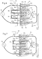
- plugs 60B and 60C there are two additional plugs 66 spaced apart so as to correspond with the sockets 26 of the short-circuiting link 24 in the housing 10.
- the plug 66 occupying the upper position is electrically connected to plug 60B by a metal braid 68, and the lower plug 66 is connected similarly to plug 60C.
- the plugs 60A and 60D are connected via respective banana plugs 64 to a signal source 70 (see FIG. 6) to supply the input terminals of the current signal in the relay 46 during the test; the plug 60E in the same way establishes a connection supplying the input terminals of the voltage signal, and the plug 60H makes it possible to control the output signal of the relay 46.
- the plugs 60B, 66 and 60C of the test plug 50 extend beyond the plugs 60A, 60B and the plungers 58.
- the plugs 60B, 66 and 60C penetrate the sockets 14B, 26 and 14C before any other contact occurs between the socket 50 and the housing 10. This results in the short-circuiting of the terminals S1 and S2 of the transformer current 40, via socket 14B, plug 60B, braid 68, upper plug 66, upper socket 26, short-circuit link 24, plate 28, the lower sleeve 26, the lower plug 66, the lower braid 68, the plug 60C and the sleeve 14C.
- the plungers 58a and 58b enter the chambers 18, and come into contact with the short-circuiting elements 16a and 16b to cut the connection between the sockets 14A and 14B on the one hand and the respective sockets 14B and 14C, on the other hand, thus interrupting the connection of the relay 46 and of the current transformer 40.
- This interruption is done without danger since the secondary circuit of the current transformer 40 is already closed by means of plugs 66 etc.
- the plugs 60A and 60D establish contact with the sockets 14A and 14D, connecting the signal source 70 to the relay 46.
- the plugs 60E and 60H (not shown in FIGS. 6 and 7) establish contact with the sockets 14E and 14H to supply the voltage signal input of relay 46 and to control its output signal.
- the socket 50 is removed, which has the effect of reversing the sequence of the preceding operations, both as regards the order and the nature of the operations (connection / disconnection) concerned.
- the relay 46 is connected again to the current transformer 40 by means of the short-circuiting elements 16 before the short-circuit effected by means of the files 60B, 66 and 60C is eliminated. Then, the cover 30 is replaced, thus re-establishing the missing connections with the relay 46 to return it to service.
- the secondary circuits of current transformers 40 have a common end for the different phases and this common connection at their end must be maintained during the test. This condition is easily satisfied using the electrical connection and test equipment described above by providing a common H-shaped connection plate 28 'for the adjacent short-circuit links 24 as shown. represented at the top right and bottom left of Figure 2.
- a test socket 50 modified in this way can advantageously be of a distinctive color, red for example, to draw attention to the fact that it cannot be inserted securely without taking additional precautions in a test box. 10 of the ordinary type as shown in FIGS. 1 and 2.
- a standard test port 50 such as that of FIG. 5, which is generally considered to be safe in all circumstances by an operator, would not risk being accidentally inserted into a modified casing as just described; in fact, the neutral plug replacing the short-circuit link 24 would prevent the insertion of the plugs 66, thus opposing the coupling.
- each pair of short-circuitable sockets 114 is aligned horizontally, the pairs of sockets being arranged in the same vertical strip on 16 lines or more.
- a connection box 92 seen from the front in FIG. 8 comprises a horizontal pair of sockets 114A1-114B1 similar to sockets 14A and 14B, short-circuitable by an element 116a similar to element 16a and a pair of sockets 114C1-114D1, short-circuitable by an element 116b, this pair being placed immediately below the pair 114A1-114B1.
- Sockets 114A1 and 114C1 are connected to respective input conductors 101 and 111 connected to the terminals of a current transformer associated with a first phase of the network on the left part of the housing 92 and sockets 114B1 and 114C1 are connected to the relay protection on the right of the housing by conductors 201 and 211, respectively.
- a short-circuit link 124 1 similar to the link 24 comprises two sockets 126 1 each aligned with one of the pairs 114A1-114B1 and 114C1-114D1 to the left of the latter and connected by a conductive plate 128 1
- sockets 114A2-114D2 and 114A3-114D3 are provided below group 114A1-114D1 with their respective short-circuiting links 124 2 and 124 3 for the connection of the protection to two current transformers respectively associated with phases 2 and 3 of the network by input and output conductors identified by reference numbers, the last digit of which corresponds to the phase with which they are associated.
- the housing 92 shown in this example also includes pairs of sockets such as 114E1-114F1, establishing the connection between voltage measurement transformers taken from the network on the left of the housing 92 and the protection relay or relays on the right of this housing , and pairs of sockets such as 114G3-114H3, from which it is possible to pick up the output signals of the protection by means of round-trip conductors such as 132-232 and 133-233.
- pairs of sockets such as 114E1-114F1
- 114G3-114H3 establishing the connection between voltage measurement transformers taken from the network on the left of the housing 92 and the protection relay or relays on the right of this housing
- pairs of sockets such as 114G3-114H3 from which it is possible to pick up the output signals of the protection by means of round-trip conductors such as 132-232 and 133-233.
- All these pairs of sockets are aligned along the same vertical strip with cavities on their left in the housing, left open such as 129 or closed by plugs such as 130, in place of short-circuit connections such as 124.
- the cover and the test socket associated with the housing 92 include plug-in elements and pushers corresponding to the arrangement described for carrying out the connection / disconnection operations according to the required sequencing.
Landscapes
- Physics & Mathematics (AREA)
- General Physics & Mathematics (AREA)
- Breakers (AREA)
- Testing Of Short-Circuits, Discontinuities, Leakage, Or Incorrect Line Connections (AREA)
Applications Claiming Priority (2)
| Application Number | Priority Date | Filing Date | Title |
|---|---|---|---|
| FR7931648 | 1979-12-26 | ||
| FR7931648A FR2472857A1 (fr) | 1979-12-26 | 1979-12-26 | Dispositifs de connexion electrique et d'essai |
Publications (1)
| Publication Number | Publication Date |
|---|---|
| EP0032083A1 true EP0032083A1 (fr) | 1981-07-15 |
Family
ID=9233151
Family Applications (1)
| Application Number | Title | Priority Date | Filing Date |
|---|---|---|---|
| EP80401790A Withdrawn EP0032083A1 (fr) | 1979-12-26 | 1980-12-12 | Dispositifs de connexion électrique et d'essai |
Country Status (5)
| Country | Link |
|---|---|
| EP (1) | EP0032083A1 (OSRAM) |
| AR (1) | AR230901A1 (OSRAM) |
| AU (1) | AU6566880A (OSRAM) |
| BR (1) | BR8008399A (OSRAM) |
| FR (1) | FR2472857A1 (OSRAM) |
Cited By (1)
| Publication number | Priority date | Publication date | Assignee | Title |
|---|---|---|---|---|
| CN113314977A (zh) * | 2021-06-22 | 2021-08-27 | 扬中海潮电力设备有限公司 | 一种可诊断系统故障的高压开关柜及其诊断方法 |
Citations (8)
| Publication number | Priority date | Publication date | Assignee | Title |
|---|---|---|---|---|
| DE455723C (de) * | 1923-08-14 | 1928-02-07 | Sigwart Ruppel Dipl Ing | Steckerschalter |
| DE599656C (de) * | 1931-06-09 | 1934-07-06 | Bbc Brown Boveri & Cie | Klemmenreihe fuer Messleitungen in elektrischen Verteilungsanlagen |
| DE691333C (de) * | 1939-02-12 | 1940-05-23 | Siemens Schuckertwerke Akt Ges | Pruefklemme |
| FR1041047A (fr) * | 1951-08-02 | 1953-10-20 | Electroniques Et Electro Mecan | Perfectionnement aux prises de courant pour l'insertion d'appareils de mesure |
| DE2256373A1 (de) * | 1972-11-17 | 1974-05-22 | Geyer Fa Christian | Steckvorrichtung fuer elektrizitaetszaehler |
| FR2223852A1 (OSRAM) * | 1973-03-30 | 1974-10-25 | Akzona Inc | |
| US3914564A (en) * | 1974-08-22 | 1975-10-21 | Square D Co | Automatic by-pass device for a watt hour meter socket |
| FR2342503A1 (fr) * | 1976-02-26 | 1977-09-23 | Alsthom Cgee | Dispositif d'essai d'une installation electrique |
-
1979
- 1979-12-26 FR FR7931648A patent/FR2472857A1/fr active Granted
-
1980
- 1980-12-12 EP EP80401790A patent/EP0032083A1/fr not_active Withdrawn
- 1980-12-19 BR BR8008399A patent/BR8008399A/pt unknown
- 1980-12-19 AR AR28373880A patent/AR230901A1/es active
- 1980-12-22 AU AU65668/80A patent/AU6566880A/en not_active Abandoned
Patent Citations (8)
| Publication number | Priority date | Publication date | Assignee | Title |
|---|---|---|---|---|
| DE455723C (de) * | 1923-08-14 | 1928-02-07 | Sigwart Ruppel Dipl Ing | Steckerschalter |
| DE599656C (de) * | 1931-06-09 | 1934-07-06 | Bbc Brown Boveri & Cie | Klemmenreihe fuer Messleitungen in elektrischen Verteilungsanlagen |
| DE691333C (de) * | 1939-02-12 | 1940-05-23 | Siemens Schuckertwerke Akt Ges | Pruefklemme |
| FR1041047A (fr) * | 1951-08-02 | 1953-10-20 | Electroniques Et Electro Mecan | Perfectionnement aux prises de courant pour l'insertion d'appareils de mesure |
| DE2256373A1 (de) * | 1972-11-17 | 1974-05-22 | Geyer Fa Christian | Steckvorrichtung fuer elektrizitaetszaehler |
| FR2223852A1 (OSRAM) * | 1973-03-30 | 1974-10-25 | Akzona Inc | |
| US3914564A (en) * | 1974-08-22 | 1975-10-21 | Square D Co | Automatic by-pass device for a watt hour meter socket |
| FR2342503A1 (fr) * | 1976-02-26 | 1977-09-23 | Alsthom Cgee | Dispositif d'essai d'une installation electrique |
Cited By (1)
| Publication number | Priority date | Publication date | Assignee | Title |
|---|---|---|---|---|
| CN113314977A (zh) * | 2021-06-22 | 2021-08-27 | 扬中海潮电力设备有限公司 | 一种可诊断系统故障的高压开关柜及其诊断方法 |
Also Published As
| Publication number | Publication date |
|---|---|
| FR2472857B1 (OSRAM) | 1981-12-11 |
| AR230901A1 (es) | 1984-07-31 |
| AU6566880A (en) | 1981-07-02 |
| FR2472857A1 (fr) | 1981-07-03 |
| BR8008399A (pt) | 1981-07-14 |
Similar Documents
| Publication | Publication Date | Title |
|---|---|---|
| US4034172A (en) | High voltage connector with crow bar | |
| FR2491846A1 (fr) | Coffret a fusibles et organes de distribution pour vehicules automobiles | |
| US4053724A (en) | Panel and plural module assembly having mechanical keying and modular plug structure to activate/deactivate automatically bridged load carrying circuits | |
| EP3242360B1 (fr) | Dispositif de verrouillage pour connecteurs électriques et connecteurs électriques équipés du dispositif | |
| EP1816710A1 (fr) | Dispositif de branchement en parallèle d'une pluralité d'appareils d'alimentation électrique | |
| EP2335263B1 (fr) | Dispositif et ensemble coulissant de connexion electrique, en particulier pour bloc de protection differentielle | |
| FR2662042A1 (fr) | Dispositif de connexion de lignes telephoniques, ce dispositif comportant au moins un module enfichable de protection contre les surtensions. | |
| EP3229034B1 (fr) | Bloc d' essai avec cage de faraday | |
| EP3229033B1 (fr) | Bloc d essai doté de prises d entrée et de sortie de type rj45 | |
| EP0081795B1 (fr) | Connecteur électrique à couplage multiple et son utilisation dans des connecteurs multiples de mesure pour cartes de circuits d'équipement électronique monté dans un châssis | |
| EP0032083A1 (fr) | Dispositifs de connexion électrique et d'essai | |
| EP0138713B1 (fr) | Dispositif de connexion pour test de circuit imprimé | |
| EP2335321B1 (fr) | Dispositif et procede de détection d'une défaillance dans un reseau electrique moyenne, haute ou tres haute tension | |
| EP3576975B1 (fr) | Dispositif de connexion electrique avec fonction de consignation integree | |
| CA1076673A (fr) | Connecteur pour essai d'une installation electrique | |
| FR2575610A1 (fr) | Bac a cartes electroniques, apte a une connexion electrique par le cote frontal | |
| FR2764742A1 (fr) | Dispositif de raccordement electrique entre un systeme a barres et un ensemble de quatre conducteurs d'alimentation d'une charge en courant triphase | |
| EP0231310B1 (fr) | Dispositif de connexion electrique prefabrique de liaison sur un jeu de barres | |
| FR2870398A1 (fr) | Dispositif de connexion securisee et fiche de connexion correspondante | |
| EP0518762A1 (fr) | Dispositif d'aide au câblage électrique et installation électrique s'y rapportant | |
| EP3340269B1 (fr) | Appareil électrique multipolaire à borne de connexion par enfichage direct orientée verticalement et système électrique interrupteur | |
| EP0353137A1 (fr) | Transformateur | |
| EP0949719B1 (fr) | Connecteur électrique notamment pour le déclenchement d'un sac gonflable de protection d'un conducteur ou d'un passager de véhicule automobile | |
| FR2529393A1 (fr) | Boitier de protection pour bloc de raccordement dans un repartiteur de telecommunication | |
| FR2947675A1 (fr) | Connecteur electrique |
Legal Events
| Date | Code | Title | Description |
|---|---|---|---|
| PUAI | Public reference made under article 153(3) epc to a published international application that has entered the european phase |
Free format text: ORIGINAL CODE: 0009012 |
|
| AK | Designated contracting states |
Designated state(s): CH DE GB IT SE |
|
| 17P | Request for examination filed |
Effective date: 19810615 |
|
| STAA | Information on the status of an ep patent application or granted ep patent |
Free format text: STATUS: THE APPLICATION IS DEEMED TO BE WITHDRAWN |
|
| 18D | Application deemed to be withdrawn |
Effective date: 19820814 |
|
| RIN1 | Information on inventor provided before grant (corrected) |
Inventor name: BARIL, PAUL Inventor name: N'GUYEN, VAN LAN |