EP0032074B1 - Thermal and acoustical insulating structure for a cladding or other non supporting walling - Google Patents
Thermal and acoustical insulating structure for a cladding or other non supporting walling Download PDFInfo
- Publication number
- EP0032074B1 EP0032074B1 EP80401736A EP80401736A EP0032074B1 EP 0032074 B1 EP0032074 B1 EP 0032074B1 EP 80401736 A EP80401736 A EP 80401736A EP 80401736 A EP80401736 A EP 80401736A EP 0032074 B1 EP0032074 B1 EP 0032074B1
- Authority
- EP
- European Patent Office
- Prior art keywords
- sheet
- thin
- ribs
- core
- thin core
- Prior art date
- Legal status (The legal status is an assumption and is not a legal conclusion. Google has not performed a legal analysis and makes no representation as to the accuracy of the status listed.)
- Expired
Links
- 238000005253 cladding Methods 0.000 title description 7
- 239000002184 metal Substances 0.000 claims description 12
- 239000011810 insulating material Substances 0.000 claims description 3
- 239000007787 solid Substances 0.000 claims description 3
- 239000011152 fibreglass Substances 0.000 claims 1
- 238000000576 coating method Methods 0.000 description 14
- 239000011248 coating agent Substances 0.000 description 9
- 238000009413 insulation Methods 0.000 description 7
- 230000003313 weakening effect Effects 0.000 description 4
- 239000011490 mineral wool Substances 0.000 description 3
- 230000005540 biological transmission Effects 0.000 description 2
- 238000013016 damping Methods 0.000 description 2
- 238000009434 installation Methods 0.000 description 2
- 239000012212 insulator Substances 0.000 description 2
- 229920001084 poly(chloroprene) Polymers 0.000 description 2
- 229910000831 Steel Inorganic materials 0.000 description 1
- 238000010521 absorption reaction Methods 0.000 description 1
- 239000000853 adhesive Substances 0.000 description 1
- 230000001070 adhesive effect Effects 0.000 description 1
- 230000015572 biosynthetic process Effects 0.000 description 1
- 230000001413 cellular effect Effects 0.000 description 1
- 238000010276 construction Methods 0.000 description 1
- 238000005755 formation reaction Methods 0.000 description 1
- 239000011521 glass Substances 0.000 description 1
- 239000003365 glass fiber Substances 0.000 description 1
- 230000000149 penetrating effect Effects 0.000 description 1
- 238000010008 shearing Methods 0.000 description 1
- 239000010959 steel Substances 0.000 description 1
Images

Classifications
-
- E—FIXED CONSTRUCTIONS
- E04—BUILDING
- E04B—GENERAL BUILDING CONSTRUCTIONS; WALLS, e.g. PARTITIONS; ROOFS; FLOORS; CEILINGS; INSULATION OR OTHER PROTECTION OF BUILDINGS
- E04B1/00—Constructions in general; Structures which are not restricted either to walls, e.g. partitions, or floors or ceilings or roofs
- E04B1/62—Insulation or other protection; Elements or use of specified material therefor
- E04B1/74—Heat, sound or noise insulation, absorption, or reflection; Other building methods affording favourable thermal or acoustical conditions, e.g. accumulating of heat within walls
- E04B1/88—Insulating elements for both heat and sound
- E04B1/90—Insulating elements for both heat and sound slab-shaped
-
- E—FIXED CONSTRUCTIONS
- E04—BUILDING
- E04F—FINISHING WORK ON BUILDINGS, e.g. STAIRS, FLOORS
- E04F13/00—Coverings or linings, e.g. for walls or ceilings
- E04F13/07—Coverings or linings, e.g. for walls or ceilings composed of covering or lining elements; Sub-structures therefor; Fastening means therefor
- E04F13/08—Coverings or linings, e.g. for walls or ceilings composed of covering or lining elements; Sub-structures therefor; Fastening means therefor composed of a plurality of similar covering or lining elements
- E04F13/0867—Coverings or linings, e.g. for walls or ceilings composed of covering or lining elements; Sub-structures therefor; Fastening means therefor composed of a plurality of similar covering or lining elements having acoustic absorption means on the visible surface
-
- E—FIXED CONSTRUCTIONS
- E04—BUILDING
- E04B—GENERAL BUILDING CONSTRUCTIONS; WALLS, e.g. PARTITIONS; ROOFS; FLOORS; CEILINGS; INSULATION OR OTHER PROTECTION OF BUILDINGS
- E04B1/00—Constructions in general; Structures which are not restricted either to walls, e.g. partitions, or floors or ceilings or roofs
- E04B1/62—Insulation or other protection; Elements or use of specified material therefor
- E04B1/74—Heat, sound or noise insulation, absorption, or reflection; Other building methods affording favourable thermal or acoustical conditions, e.g. accumulating of heat within walls
- E04B1/82—Heat, sound or noise insulation, absorption, or reflection; Other building methods affording favourable thermal or acoustical conditions, e.g. accumulating of heat within walls specifically with respect to sound only
- E04B1/84—Sound-absorbing elements
- E04B2001/8414—Sound-absorbing elements with non-planar face, e.g. curved, egg-crate shaped
-
- E—FIXED CONSTRUCTIONS
- E04—BUILDING
- E04B—GENERAL BUILDING CONSTRUCTIONS; WALLS, e.g. PARTITIONS; ROOFS; FLOORS; CEILINGS; INSULATION OR OTHER PROTECTION OF BUILDINGS
- E04B1/00—Constructions in general; Structures which are not restricted either to walls, e.g. partitions, or floors or ceilings or roofs
- E04B1/62—Insulation or other protection; Elements or use of specified material therefor
- E04B1/74—Heat, sound or noise insulation, absorption, or reflection; Other building methods affording favourable thermal or acoustical conditions, e.g. accumulating of heat within walls
- E04B1/82—Heat, sound or noise insulation, absorption, or reflection; Other building methods affording favourable thermal or acoustical conditions, e.g. accumulating of heat within walls specifically with respect to sound only
- E04B1/84—Sound-absorbing elements
- E04B2001/8457—Solid slabs or blocks
- E04B2001/8461—Solid slabs or blocks layered
- E04B2001/8471—Solid slabs or blocks layered with non-planar interior transition surfaces between layers, e.g. faceted, corrugated
-
- E—FIXED CONSTRUCTIONS
- E04—BUILDING
- E04B—GENERAL BUILDING CONSTRUCTIONS; WALLS, e.g. PARTITIONS; ROOFS; FLOORS; CEILINGS; INSULATION OR OTHER PROTECTION OF BUILDINGS
- E04B1/00—Constructions in general; Structures which are not restricted either to walls, e.g. partitions, or floors or ceilings or roofs
- E04B1/62—Insulation or other protection; Elements or use of specified material therefor
- E04B1/74—Heat, sound or noise insulation, absorption, or reflection; Other building methods affording favourable thermal or acoustical conditions, e.g. accumulating of heat within walls
- E04B1/82—Heat, sound or noise insulation, absorption, or reflection; Other building methods affording favourable thermal or acoustical conditions, e.g. accumulating of heat within walls specifically with respect to sound only
- E04B1/84—Sound-absorbing elements
- E04B2001/8457—Solid slabs or blocks
- E04B2001/8476—Solid slabs or blocks with acoustical cavities, with or without acoustical filling
- E04B2001/848—Solid slabs or blocks with acoustical cavities, with or without acoustical filling the cavities opening onto the face of the element
Definitions
- thermo-acoustic insulating structure for cladding, or other non-load-bearing wall, comprising a thermally insulating panel held between metallic coatings, respectively internal and external, provided with ribs projecting from the panel, the ribs of the two coatings being perpendicular. between them.
- the two main factors of the acoustic weakening are the volumetric mass of the structure and, consequently, the density and the thickness of the various components, and the distance between the successive components.
- a known insulating structure (FR-A-1 288 854), comprising a thermal insulator maintained between two metallic coatings, absorbs insufficiently the internal noises if the internal coating is not perforated, but this perforation reduces the weakening of external noise.
- a significant improvement in insulation is obtained by giving the internal coating the form of a closed box containing a high density insulation (FR-A-2 415 696), but this improvement is limited by the requirements of lightness and low space, when it is a cladding or the like.
- the present invention therefore aims to solve this problem by improving the insulation qualities of known structures without significantly increasing their weight or their thickness.
- the object of this invention is in fact an insulating structure of the type in which a thermally insulating panel is held between metallic coatings, respectively internal and external, provided with ribs projecting from the panel, the ribs of each coating being perpendicular to those of the other, which comprises a thin core, for example having a thickness of the order of 2 to 4 mm, of insulating material, applied by a full and thin metal sheet, preferably a sheet of 1 mm (10 / 10th), against a full plate of one of the coatings.
- the thin core has a laminated structure, elastic, and having a high resistance to the passage of air.
- the metal sheet is thin and it is fixed to the core only by its attachment to the covering, that is to say at the level of the ribs, the core being only pinched at these points so that it does not not likely to work in shear.
- the core and the sheet can be placed on the external covering, the sheet then having ribs similar to those of this covering which fit into them, or be mounted on the internal covering between it and the insulation. thermal.
- the insulating structure comprises an internal covering 1 and an external covering or tank 2 between which is held a panel made of thermally insulating material 4.
- the internal coating 1 is constituted by a series of U-section plates, nested one after the other.
- the lateral wings 6 of each of the plates 1 a, 1 b, are folded at their free end, all in the same direction so as to be able to hang on the wings of the adjacent plate.
- the bottom of each plate is provided with ribs 8, parallel to the wings 6 and projecting in the same direction.
- the outer tank 2 On the opposite face of the panel 4 the outer tank 2 is constituted by a relatively thin sheet metal, provided with ribs 10 projecting in the direction of the panel 4 and in contact therewith, but perpendicular to the ribs 8 and wings 6 of the covering 1.
- the interior coverings 1 and exterior coverings 2 are fixed to each other locally, at the crossing points of the ribs 10 and wings 6, so as to ensure the assembly of the structure.
- the insulating structure further comprises a thin core 12 which covers the outer surface of the covering 2 by conforming to its shape, that is to say by penetrating into the ribs 10.
- the core 12 is preferably made of a veil of glass fibers having a laminated structure, that is to say comprising several layers, in fa to show great resistance to air.
- This veil 12 is itself covered by a thin sheet 14 of steel, or other similar metal, provided with ribs 16 similar to the ribs 10 of the tank 2 and fitting into them.
- the core 12 is thus pinched between the ribs 10 and 16 and kept in contact with the tank 2 and the sheet metal 14 without it being necessary to use any fixing means for this.
- the absence of bonding or other means of securing the core 12 with the sheets 14 or 2 avoids any risk of shearing work of this core which may cause deformations or act on the frequency of resonance of the whole.
- the veil 12 has a very small thickness, of the order of 2 to 4 mm, and preferably 2 mm.
- the sheet 14 is preferably a sheet of 1 mm (10 / 10th).
- this double wall significantly increases the performance of the structure and in particular the acoustic reduction obtained by means of this wall.
- This attenuation is particularly sensitive to low frequencies since the resonant frequency of the structure is lowered below 100 Hz, that is to say practically below the usual resonant frequencies on the metallic double walls (from 100 to 315 Hz).
- Such a structure therefore provides effective protection against airborne noise, and this with an increase in weight and small thickness compared to those of known structures.
- the increase in thickness can also be further reduced, and even practically eliminated, by producing the insulating structure as shown in FIG. 2.
- a thin core 22 is mounted against the coating 1, between the latter and a thin sheet 24.
- the thin core 22 is then applied against the ribs 8 of each of the plates 1a, 1b, and curved at its ends against the wings 6 of this tray.
- the sheet 24, bent at its two ends, is fitted into each plate 1a, 1b, and fixed on the wings 6 of this plate.
- the panel 4 made of mineral wool felt, or any other thermal insulator, is in contact with the successive sheets 24, on either side of the wings 6 connecting between the various plates.
- This panel may have the same thickness as that used in the embodiment of FIG. 1 or have a slightly smaller thickness, so as to give the whole of the structure a thickness which is less than that of the structure without a web. of glass and sheet metal 14, the external coating 2 being produced in the same way by means of a thin sheet metal provided with ribs 10.
- the web 22 is simply pinched between the sheet 24 and the ribs 8 of the covering against which it is placed. No particular means of adhesion or fixing is necessary.
- Such a structure also meets the lightness requirements of cladding or other facings of buildings and in particular of industrial buildings.
- this coating is produced in the form of boxes, as shown in the figure 3.
- Each box of this internal coating then comprises a U-shaped plate, perforated, 31, between the wings 36 of which is fitted a solid sheet 32 which holds a thin panel of high density mineral wool 34, filling the space between the full sheet 32 and the perforated plate 31.
- the thin core 22 is then mounted against the sheet 32 for closing the box and the sheet 24 maintains this core 22 between the wings 36 of the plate.
- a panel of mineral wool felt 4, or the like covers the ribs formed by the wings 36 of the successive plates and is protected by an external tank 2 comprising ribs 10 perpendicular to these wings 36.
- the structure thus produced provides real damping of interior noise thanks to the perforation of the internal plate 31, but has a significant sound reduction index thanks to the combination of the walls 32 and 24 with the thin core 22, which is added to the action of the outer tank 2 and of the insulation 4.
- This structure which may have a thickness very close to that of the embodiment of FIG. 2, has a very low resonance frequency which no longer interferes with the acoustic attenuation and makes it possible to obtain a curve of weakening which rises in an almost regular way as a function of the frequency, and that starting from frequencies lower than 100 hz.
- This structure is particularly suitable for making facing or cladding of buildings, or other non-load-bearing walls, intended to be placed on elements of metal or concrete.
- the plate 1 (fig. 1 and 2) or the box 31 (fig. 3) are mechanically attached to the supporting frame by any suitable means.
- a flexible joint (polychloroprene type sold under the trademark Neoprene or flexible cellular PVC) can be interposed between the supporting structure and the plate or box in order to reduce the transmission of vibrations from the frame to the wall.
- the air tightness and therefore the acoustic insulation of the wall are also reinforced by the installation, on the wing 6 of the plate 1 or 36 of the plate 31, of a flexible adhesive seal. This joint is pinched during installation between the various plates which fit together successively.
- the per Formations obtained are close to those of a concrete veil of several hundred kg / m 2 .
Description
La présente invention concerne une structure isolante thermo-acoustique pour bardage, ou autre paroi non porteuse, comportant un panneau thermiquement isolant maintenu entre des revêtements métalliques respectivement interne et externe, munis de nervures en saillie dans le panneau, les nervures des deux revêtements étant perpendiculaires entre elles.The present invention relates to a thermo-acoustic insulating structure for cladding, or other non-load-bearing wall, comprising a thermally insulating panel held between metallic coatings, respectively internal and external, provided with ribs projecting from the panel, the ribs of the two coatings being perpendicular. between them.
Il existe actuellement de nombreux types d'éléments de construction ou de structures destinés à l'isolation thermique et acoustique. Malheureusement les normes de confort et le volume croissant des bruits sont tels que ces éléments ne répondent pas de manière satisfaisante aux besoins.There are currently many types of building elements or structures intended for thermal and acoustic insulation. Unfortunately, the standards of comfort and the increasing volume of noise are such that these elements do not meet needs satisfactorily.
L'amélioration de leur efficacité est tout particulièrement difficile lorsqu'ils sont destinés à des bardages ou autres parois non porteuses, qui doivent présenter une grande légèreté et une faible épaisseur. En effet, les deux facteurs principaux de l'affaiblissement acoustique sont la masse volumétrique de la structure et, par suite, la densité et l'épaisseur des divers composants, et la distance entre les composants successifs.Improving their effectiveness is particularly difficult when they are intended for cladding or other non-load-bearing walls, which must be very light and thin. Indeed, the two main factors of the acoustic weakening are the volumetric mass of the structure and, consequently, the density and the thickness of the various components, and the distance between the successive components.
Par ailleurs, les conditions de l'absorption des bruits intérieurs sont généralement peu compatibles avec un affaiblissement efficace de la transmission des bruits extérieurs ou aériens.In addition, the conditions for absorption of interior noise are generally not very compatible with an effective weakening of the transmission of exterior or air noise.
Par exemple, une structure isolante connue (FR-A-1 288 854), comportant un isolant thermique maintenu entre deux revêtements métalliques, amortit de manière insuffisante les bruits intérieurs si le revêtement interne n'est pas perforé, mais cette perforation réduit l'affaiblissement des bruits extérieurs.For example, a known insulating structure (FR-A-1 288 854), comprising a thermal insulator maintained between two metallic coatings, absorbs insufficiently the internal noises if the internal coating is not perforated, but this perforation reduces the weakening of external noise.
Une amélioration importante de l'isolement est obtenue en donnant au revêtement interne la forme d'un caisson fermé contenant un isolant à forte densité (FR-A-2 415 696), mais cette amélioration est limitée par les exigences de légèreté et de faible encombrement, lorsqu'il s'agit d'un bardage ou analogue.A significant improvement in insulation is obtained by giving the internal coating the form of a closed box containing a high density insulation (FR-A-2 415 696), but this improvement is limited by the requirements of lightness and low space, when it is a cladding or the like.
La présente invention a donc pour but the résoudre ce problème en améliorant les qualités d'isolement des structures connues sans accroître, de façon notable, leur poids ni leur épaisseur.The present invention therefore aims to solve this problem by improving the insulation qualities of known structures without significantly increasing their weight or their thickness.
Cette invention a en effet pour objet une structure isolante du type dans lequel un panneau thermiquement isolant est maintenu entre des revêtements métalliques, respectivement interne et externe, munis de nervures en saillie dans le panneau, les nervures de chaque revêtement étant perpendiculaires à celles de l'autre, qui comporte une âme mince, ayant par exemple une épaisseur de l'ordre de 2 à 4 mm, en matériau isolant, appliquée par une tôle métallique pleine et mince, de préférence une tôle de 1 mm (10/10ème), contre une plaque pleine de l'un des revêtements.The object of this invention is in fact an insulating structure of the type in which a thermally insulating panel is held between metallic coatings, respectively internal and external, provided with ribs projecting from the panel, the ribs of each coating being perpendicular to those of the other, which comprises a thin core, for example having a thickness of the order of 2 to 4 mm, of insulating material, applied by a full and thin metal sheet, preferably a sheet of 1 mm (10 / 10th), against a full plate of one of the coatings.
De préférence, l'âme mince a une structure stratifiée, élastique, et présentant une grande résistance au passage de l'air.Preferably, the thin core has a laminated structure, elastic, and having a high resistance to the passage of air.
La tôle métallique est mince et elle n'est fixée à l'âme que par sa fixation sur le revêtement, c'est-à-dire au droit des nervures, l'âme étant seulement pincée en ces points de sorte qu'elle ne risque pas de travailler au cisaillement.The metal sheet is thin and it is fixed to the core only by its attachment to the covering, that is to say at the level of the ribs, the core being only pinched at these points so that it does not not likely to work in shear.
On constate alors que malgré la faible masse de l'âme et de la tôle l'affaiblissement acoustique est nettement amélioré, surtout aux basses fréquences. La fréquence de résonance de la structure est en effet considérablement abaissée.It can then be seen that despite the low mass of the core and of the sheet, the acoustic attenuation is clearly improved, especially at low frequencies. The resonant frequency of the structure is in fact considerably lowered.
Bien entendu l'âme et la tôle peuvent être disposées sur le revêtement extérieur, la tôle ayant alors des nervures semblables à celles de ce revêtement qui s'emboîtent dans celles-ci, ou être montées sur le revêtement interne entre lui et l'isolant thermique.Of course, the core and the sheet can be placed on the external covering, the sheet then having ribs similar to those of this covering which fit into them, or be mounted on the internal covering between it and the insulation. thermal.
La description ci-dessous de modes de réalisation représentés aux dessins annexés, fera ressortir les avantages et caractéristiques de l'invention.The description below of embodiments shown in the accompanying drawings will highlight the advantages and characteristics of the invention.
Sur ces dessins:
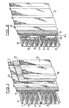
- la fig. 1 est une vue schématique en perspective, avec arrachement partiel, d'une portion de structure isolante selon l'invention;
- les fig. 2 et 3 sont des vues analogues à la figure 1, de variantes de réalisation de la structure isolante.
- fig. 1 is a schematic perspective view, with partial cutaway, of a portion of insulating structure according to the invention;
- fig. 2 and 3 are views similar to Figure 1, of alternative embodiments of the insulating structure.
Comme le montre la figure 1, la structure isolante comporte un revêtement interne 1 et un revêtement ou bac externe 2 entre lesquels est maintenu un panneau en matériau thermiquement isolant 4.As shown in FIG. 1, the insulating structure comprises an internal covering 1 and an external covering or tank 2 between which is held a panel made of thermally insulating material 4.
Dans le mode de réalisation représenté, le revêtement interne 1 est constitué par une série de plateaux de section en U, emboîtés les uns à la suite des autres. Les ailes latérales 6 de chacun des plateaux 1 a, 1 b, sont repliées à leur extrémité libre, toutes dans le même sens de façon à pouvoir s'accrocher sur les ailes du plateau adjacent. En outre le fond de chaque plateau est muni de nervures 8, parallèles aux ailes 6 et en saillie dans la même direction.In the embodiment shown, the internal coating 1 is constituted by a series of U-section plates, nested one after the other. The
Ces nervures 8, comme les ailes 6, assurent le maintien du panneau isolant 4 qui est, de préférence, d'une seule pièce et s'emboîte sur la succession de plateaux 1 a, 1 b, etc.These
Sur la face opposée du panneau 4 le bac extérieur 2 est constitué par une tôle relativement mince, munie de nervures 10 en saillie en direction du panneau 4 et en contact avec celui-ci, mais perpendiculaires aux nervures 8 et ailes 6 du revêtement 1. Les revêtements intérieur 1 et extérieur 2 sont fixés entre eux localement, aux points de croisement des nervures 10 et ailes 6, de façon à assurer l'assemblage de la structure.On the opposite face of the panel 4 the outer tank 2 is constituted by a relatively thin sheet metal, provided with
Selon l'invention la structure isolante comporte en outre une âme mince 12 qui recouvre la surface extérieure du revêtement 2 en épousant sa forme, c'est-à-dire en pénétrant dans les nervures 10.According to the invention, the insulating structure further comprises a
L'âme 12 est de préférence réalisée en un voile de fibres de verre ayant une structure stratifiée, c'est-à-dire comportant plusieurs couches, de façon à présenter une grande résistance à l'air. Ce voile 12 est lui-même recouvert par une tôle mince 14 en acier, ou autre métal analogue, munie de nervures 16 analogues aux nervures 10 du bac 2 et s'emboîtant dans celles-si. L'âme 12 est ainsi pincée entre les nervures 10 et 16 et maintenue en contact avec le bac 2 et la tôle 14 sans qu'il soit nécessaire d'utiliser un moyen quelconque de fixation pour cela.The
Les organes fixant la tôle 14 et la tôle du bac 2 et traversant ces tôles au droit des ailes 6 du revêtement 1 suffisent à maintenir efficacement l'âme 12.The members fixing the
Par ailleurs, l'absence de collage ou d'autres moyens de solidarisation de l'âme 12 avec les tôles 14 ou 2 évite tout risque de travail au cisaillement de cette âme susceptible d'entraîner des déformations ou d'agir sur la fréquence de résonance de l'ensemble.Furthermore, the absence of bonding or other means of securing the
Le voile 12 présente une épaisseur très faible, de l'ordre de 2 à 4 mm, et de préférence de 2 mm. De même la tôle 14 est de préférence une tôle de 1 mm (10/10ème). Par suite le bac extérieure 2, combiné à l'âme 12 et à la tôle 14, constitue une double paroi de très faible épaisseur sur la face extérieure de la structure isolante.The
On constate toutefois que cette double paroi augmente de manière notable les performances de la structure et notamment l'affaiblissement acoustique obtenu au moyen de cette paroi. Cet affaiblissement est tout particulièrement sensible aux fréquences basses puisque la fréquence de résonance de la structure est abaissée en dessous de 100 hz, c'est-à-dire pratiquement en-dessous des fréquences de résonances habituelles sur les parois doubles métalliques (de 100 à 315 hz).However, it is noted that this double wall significantly increases the performance of the structure and in particular the acoustic reduction obtained by means of this wall. This attenuation is particularly sensitive to low frequencies since the resonant frequency of the structure is lowered below 100 Hz, that is to say practically below the usual resonant frequencies on the metallic double walls (from 100 to 315 Hz).
Une telle structure assure donc une protection effective contre les bruits aériens, et cela avec un accroissement de poids et d'épaisseur faible par rapport à ceux des structures connues.Such a structure therefore provides effective protection against airborne noise, and this with an increase in weight and small thickness compared to those of known structures.
L'accroissement d'épaisseur peut d'ailleurs être encore réduit, et même pratiquement supprimé, en réalisant la structure isolante de la manière représentée sur la figure 2.The increase in thickness can also be further reduced, and even practically eliminated, by producing the insulating structure as shown in FIG. 2.
En effet, dans ce mode de réalisation, une âme mince 22 est montée contre le revêtement 1, entre celui-ci et une tôle mince 24. L'âme mince 22 est alors appliquée contre les nervures 8 de chacun des plateaux 1a, 1b, et recourbée à ses extrémités contre les ailes 6 de ce plateau.In fact, in this embodiment, a
De la même manière, la tôle 24, recourbée à ses deux extrémités, est emboîtée dans chaque plateau 1a, 1b, et fixée sur les ailes 6 de ce plateau. Le panneau 4 en feutre de laine minérale, ou tout autre isolant thermique, est en contact avec les tôles 24 successives, de part et d'autre des ailes 6 de liaison entre les différents plateaux. Ce panneau peut avoir la même épaisseur que celui utilisé dans le mode de réalisation de la figure 1 ou avoir une épaisseur légèrement plus faible, de façon à donner à l'ensemble de la structure une épaisseur inférieure correspondant à celle de la structure dépourvue de voile de verre et de tôle 14, le revêtement extérieur 2 étant réalisé de la même manière au moyen d'une tôle mince munie de nervures 10.In the same way, the
Dans ce cas, comme dans le précédent, le voile 22 est simplement pincé entre la tôle 24 et les nervures 8 du revêtement contre lequel il est placé. Aucun moyen particulier d'adhérence ou de fixation n'est nécessaire.In this case, as in the previous one, the
Une telle structure répond également aux exigences de légèreté des bardages ou autres parements de bâtiments et notamment de bâtiments industriels.Such a structure also meets the lightness requirements of cladding or other facings of buildings and in particular of industrial buildings.
Lorsque l'amortissement des bruits intérieurs est un paramètre important de la réalisation du bardage, il peut être jugé utile de perforer le revêtement interne et de préférence, dans ce cas, ce revêtement est réalisé sous la forme de caissons, ainsi que le montre la figure 3.When the damping of interior noise is an important parameter in the construction of the cladding, it may be considered useful to perforate the internal coating and preferably, in this case, this coating is produced in the form of boxes, as shown in the figure 3.
Chaque caisson de ce revêtement interne comporte alors un plateau en U, perforé, 31, entre les ailes 36 duquel est emboîtée une tôle pleine 32 qui maintient un panneau mince de laine minérale de forte densité 34, remplissant l'espace entre la tôle pleine 32 et le plateau perforé 31. L'âme mince 22 est alors montée contre la tôle 32 de fermeture du caisson et la tôle 24 maintient cette âme 22 entre les ailes 36 du plateau. Comme dans les cas précédents un panneau en feutre de laine minérale 4, ou analogue, recouvre les nervures formées par les ailes 36 des plateaux successifs et est protégé par un bac extérieur 2 comportant des nervures 10 perpendiculaires à ces ailes 36.Each box of this internal coating then comprises a U-shaped plate, perforated, 31, between the
La structure ainsi réalisée assure un amortissement réel des bruits intérieurs grâce à la perforation du plateau interne 31, mais présente un indice d'affaiblissement acoustique important grâce à la combinaison des parois 32 et 24 avec l'âme mince 22, qui s'ajoute à l'action du bac extérieur 2 et de l'isolant 4. Cette structure, qui peut avoir une épaisseur très voisine de celle du mode de réalisation de la figure 2, a une fréquence de résonance très basse qui ne gêne plus l'affaiblissement acoustique et permet d'obtenir une courbe d'affaiblissement qui s'élève de façon presque régulière en fonction de la fréquence, et cela à partir de fréquences inférieures à 100 hz.The structure thus produced provides real damping of interior noise thanks to the perforation of the
Cette structure dont tous les éléments sont légers et relativement minces est particulièrement adaptée à la réalisation de parements ou bardages de bâtiments, ou autres parois non porteuses, destinés à être posés sur des éléments en métal ou en béton. Le plateau 1 (fig. 1 et 2) ou le caisson 31 (fig. 3) sont fixés mécaniquement à l'ossature porteuse par tous moyens appropriés. Un joint souple (type polychloroprène vendu sous la marque déposée Néoprène ou PVC cellulaire souple) peut être interposé entre la structure porteuse et le plateau ou caisson afin de réduire la transmission des vibrations de l'ossature à la paroi. L'étanchéité à l'air et donc l'isolement acoustique de la paroi sont renforcés également par la mise en place, sur l'aile 6 du plateau 1 ou 36 du plateau 31, d'un joint souple adhésif. Ce joint est pincé lors de la pose entre les différents plateaux qui s'emboîtent successivement. Les performances obtenues sont voisines de celles d'un voile de béton de plusieurs centaines de kg/m2.This structure, all of the elements of which are light and relatively thin, is particularly suitable for making facing or cladding of buildings, or other non-load-bearing walls, intended to be placed on elements of metal or concrete. The plate 1 (fig. 1 and 2) or the box 31 (fig. 3) are mechanically attached to the supporting frame by any suitable means. A flexible joint (polychloroprene type sold under the trademark Neoprene or flexible cellular PVC) can be interposed between the supporting structure and the plate or box in order to reduce the transmission of vibrations from the frame to the wall. The air tightness and therefore the acoustic insulation of the wall are also reinforced by the installation, on the
Claims (7)
Applications Claiming Priority (2)
| Application Number | Priority Date | Filing Date | Title |
|---|---|---|---|
| FR7931583 | 1979-12-24 | ||
| FR7931583A FR2472640A1 (en) | 1979-12-24 | 1979-12-24 | THERMAL AND ACOUSTIC INSULATION STRUCTURE FOR CLADDING OR OTHER NON-CARRIER WALL |
Publications (2)
| Publication Number | Publication Date |
|---|---|
| EP0032074A1 EP0032074A1 (en) | 1981-07-15 |
| EP0032074B1 true EP0032074B1 (en) | 1984-08-22 |
Family
ID=9233127
Family Applications (1)
| Application Number | Title | Priority Date | Filing Date |
|---|---|---|---|
| EP80401736A Expired EP0032074B1 (en) | 1979-12-24 | 1980-12-05 | Thermal and acoustical insulating structure for a cladding or other non supporting walling |
Country Status (7)
| Country | Link |
|---|---|
| US (1) | US4434592A (en) |
| EP (1) | EP0032074B1 (en) |
| BE (1) | BE886834A (en) |
| DE (1) | DE3069040D1 (en) |
| ES (1) | ES255435Y (en) |
| FR (1) | FR2472640A1 (en) |
| IT (1) | IT8068971A0 (en) |
Families Citing this family (50)
| Publication number | Priority date | Publication date | Assignee | Title |
|---|---|---|---|---|
| FR2510641A1 (en) * | 1981-07-31 | 1983-02-04 | Smac Acieroid | Self-supporting reinforcing insert for cladding - has inclined strakes supporting secondary insulating panel |
| DE3409768A1 (en) * | 1984-03-16 | 1985-09-19 | Allen Stefan Dipl.-Ing. 4000 Düsseldorf Wojcinski | ROOM CONTAINER SHOOTING RANGE |
| FR2589904B1 (en) * | 1985-11-13 | 1988-01-29 | Smac Acieroid | THERMO-ACOUSTIC INSULATING WALL. |
| US4964618A (en) * | 1986-09-23 | 1990-10-23 | Cyclops Corporation | Fence system and components |
| US4838524A (en) * | 1987-09-08 | 1989-06-13 | Cyclops Corporation | Noise barrier |
| US5425207A (en) * | 1994-02-22 | 1995-06-20 | Shayman; Harry I. | Method of constructing buildings and other structures using corrugated material |
| US5426908A (en) * | 1994-02-22 | 1995-06-27 | Shayman; Harry I. | Method of construction using corrugated material |
| NL1002839C2 (en) * | 1996-04-10 | 1997-10-14 | Rockwool Lapinus Bv | Insulated metal wall construction. |
| FR2757195B1 (en) * | 1996-12-18 | 1999-03-05 | Pab Services | THERMOACOUSTIC INSULATION PANEL FOR BUILDINGS AND METHODS OF MANUFACTURING SUCH A PANEL |
| US5850712A (en) * | 1997-06-30 | 1998-12-22 | Errato; Robert M. | Theater |
| CZ292801B6 (en) * | 1997-08-07 | 2003-12-17 | Saint-Gobain Isover | Wall panel for a building fa ade, screw for use in the wall panel and an insulation material plate for insertion into the wall panel |
| US6745531B1 (en) * | 2000-07-31 | 2004-06-08 | Construction Research & Technology Gmbh | Pressure equalized compartment for exterior insulation and finish system |
| US7093814B2 (en) * | 2002-06-05 | 2006-08-22 | Kinetics Noise Control, Inc. | Vibration isolating mount |
| ES2292266B1 (en) * | 2003-06-09 | 2008-11-16 | Juan Antonio Hereza Lebron | MODULAR AUTOPORTING PANEL FOR THE CONSTRUCTION OF VERTICAL PARAMENTS. |
| FR2883864B1 (en) * | 2005-04-01 | 2007-06-15 | Saint Gobain Isover Sa | COMPOSITIONS FOR GLASS FIBERS |
| US8186119B1 (en) * | 2006-12-21 | 2012-05-29 | Mitek Holdings, Inc. | Thermal isolating housing structure |
| US20080202846A1 (en) * | 2007-02-23 | 2008-08-28 | Mtec, Llc | Device and method for dampening sound transmission and vibration |
| US10563399B2 (en) | 2007-08-06 | 2020-02-18 | California Expanded Metal Products Company | Two-piece track system |
| US8555566B2 (en) | 2007-08-06 | 2013-10-15 | California Expanded Metal Products Company | Two-piece track system |
| US8087205B2 (en) | 2007-08-22 | 2012-01-03 | California Expanded Metal Products Company | Fire-rated wall construction product |
| US10619347B2 (en) | 2007-08-22 | 2020-04-14 | California Expanded Metal Products Company | Fire-rated wall and ceiling system |
| US20090173025A1 (en) * | 2008-01-07 | 2009-07-09 | Ralph Michael Fay | Wall system and method of forming same |
| US7757810B2 (en) | 2008-04-03 | 2010-07-20 | Soundtech, Inc. | Transparent acoustical laminate wall system and method of forming same |
| US8671632B2 (en) | 2009-09-21 | 2014-03-18 | California Expanded Metal Products Company | Wall gap fire block device, system and method |
| US8572900B1 (en) | 2010-01-22 | 2013-11-05 | Epic Metals Corporation | Decking having a removable rib |
| US9683364B2 (en) * | 2010-04-08 | 2017-06-20 | California Expanded Metal Products Company | Fire-rated wall construction product |
| US10184246B2 (en) | 2010-04-08 | 2019-01-22 | California Expanded Metal Products Company | Fire-rated wall construction product |
| ES2554556B1 (en) * | 2011-08-19 | 2016-09-27 | Acieroid, S.A. | Manufacturing process of metal enclosures for roofs and facades with built-in acoustic veil |
| US10077550B2 (en) | 2012-01-20 | 2018-09-18 | California Expanded Metal Products Company | Fire-rated joint system |
| US9212485B2 (en) * | 2012-07-13 | 2015-12-15 | Victor Wolynski | Modular building panel |
| ES2398795B1 (en) * | 2012-11-12 | 2014-01-07 | Monobi Inversions, S.L. | Construction enclosure |
| USD745338S1 (en) * | 2013-11-08 | 2015-12-15 | Fam | Knife |
| US9376810B2 (en) * | 2014-04-25 | 2016-06-28 | Usg Interiors, Llc | Multi-layer ceiling tile |
| US9879421B2 (en) | 2014-10-06 | 2018-01-30 | California Expanded Metal Products Company | Fire-resistant angle and related assemblies |
| NL2014055B1 (en) * | 2014-12-24 | 2016-09-30 | Insulation Solutions B V | Method and assembly for covering or covering structures. |
| US9752318B2 (en) | 2015-01-16 | 2017-09-05 | California Expanded Metal Products Company | Fire blocking reveal |
| US10000923B2 (en) | 2015-01-16 | 2018-06-19 | California Expanded Metal Products Company | Fire blocking reveal |
| US10113768B2 (en) | 2015-01-23 | 2018-10-30 | Mitek Holdings, Inc. | Insulated panel assembly |
| US9551148B2 (en) | 2015-01-27 | 2017-01-24 | California Expanded Metal Products Company | Header track with stud retention feature |
| KR20180058857A (en) | 2015-05-05 | 2018-06-01 | 쓰리엠 이노베이티브 프로퍼티즈 컴파니 | Curable composition for sound barrier film |
| CA2989713A1 (en) | 2016-12-20 | 2018-06-20 | Clarkwestern Dietrich Building Systems Llc | Finishing accessory with backing strip seal for wall construction |
| US10316516B2 (en) | 2017-01-23 | 2019-06-11 | Mitek Holdings, Inc. | Insulated panel assembly |
| US10753084B2 (en) | 2018-03-15 | 2020-08-25 | California Expanded Metal Products Company | Fire-rated joint component and wall assembly |
| US10689842B2 (en) | 2018-03-15 | 2020-06-23 | California Expanded Metal Products Company | Multi-layer fire-rated joint component |
| US11162259B2 (en) | 2018-04-30 | 2021-11-02 | California Expanded Metal Products Company | Mechanically fastened firestop flute plug |
| CA3052184C (en) | 2018-08-16 | 2022-11-29 | California Expanded Metal Products Company | Fire or sound blocking components and wall assemblies with fire or sound blocking components |
| US10914065B2 (en) | 2019-01-24 | 2021-02-09 | California Expanded Metal Products Company | Wall joint or sound block component and wall assemblies |
| US11268274B2 (en) | 2019-03-04 | 2022-03-08 | California Expanded Metal Products Company | Two-piece deflection drift angle |
| US11920343B2 (en) | 2019-12-02 | 2024-03-05 | Cemco, Llc | Fire-rated wall joint component and related assemblies |
| US11885138B2 (en) | 2020-11-12 | 2024-01-30 | Clarkwestern Dietrich Building Systems Llc | Control joint |
Citations (2)
| Publication number | Priority date | Publication date | Assignee | Title |
|---|---|---|---|---|
| FR1288854A (en) * | 1961-02-15 | 1962-03-30 | Acieroid | Self-supporting cladding device |
| FR2415696A1 (en) * | 1978-01-26 | 1979-08-24 | Smac Acieroid | THERMO-ACOUSTIC INSULATION WALL |
Family Cites Families (1)
| Publication number | Priority date | Publication date | Assignee | Title |
|---|---|---|---|---|
| FR2363674A1 (en) * | 1976-08-31 | 1978-03-31 | Guerard Pierre Henri | Industrial curtain walling assembly - consists of panels of galvanised steel and asbestos cement separated by insulation |
-
1979
- 1979-12-24 FR FR7931583A patent/FR2472640A1/en active Granted
-
1980
- 1980-12-05 DE DE8080401736T patent/DE3069040D1/en not_active Expired
- 1980-12-05 EP EP80401736A patent/EP0032074B1/en not_active Expired
- 1980-12-12 US US06/215,923 patent/US4434592A/en not_active Expired - Fee Related
- 1980-12-18 ES ES1980255435U patent/ES255435Y/en not_active Expired
- 1980-12-23 IT IT8068971A patent/IT8068971A0/en unknown
- 1980-12-23 BE BE0/203301A patent/BE886834A/en not_active IP Right Cessation
Patent Citations (2)
| Publication number | Priority date | Publication date | Assignee | Title |
|---|---|---|---|---|
| FR1288854A (en) * | 1961-02-15 | 1962-03-30 | Acieroid | Self-supporting cladding device |
| FR2415696A1 (en) * | 1978-01-26 | 1979-08-24 | Smac Acieroid | THERMO-ACOUSTIC INSULATION WALL |
Also Published As
| Publication number | Publication date |
|---|---|
| BE886834A (en) | 1981-06-23 |
| ES255435U (en) | 1982-06-01 |
| DE3069040D1 (en) | 1984-09-27 |
| US4434592A (en) | 1984-03-06 |
| FR2472640A1 (en) | 1981-07-03 |
| EP0032074A1 (en) | 1981-07-15 |
| FR2472640B1 (en) | 1983-07-22 |
| ES255435Y (en) | 1982-12-01 |
| IT8068971A0 (en) | 1980-12-23 |
Similar Documents
| Publication | Publication Date | Title |
|---|---|---|
| EP0032074B1 (en) | Thermal and acoustical insulating structure for a cladding or other non supporting walling | |
| EP3204566B1 (en) | Non linear dynamic absorber and its acoustic isolation usage | |
| WO2008050028A2 (en) | Acoustic insulating glazing and hollow section constituting an acoustic damping device | |
| EP0317380A1 (en) | Lining with low sound reflectivity | |
| FR2723135A1 (en) | INSULATING GLASS | |
| EP0433164B1 (en) | Insulating and fireproofed partitioning panel | |
| EP0461328A1 (en) | Sound insulation system for use in the interior of a room | |
| FR2635603A1 (en) | Internal acoustic absorption wall | |
| FR2959056A1 (en) | ACOUSTIC INSULATION DEVICE AND METHOD FOR MANUFACTURING THE SAME | |
| FR2462522A1 (en) | Demountable noise barrier panel - uses lead membrane sandwiched between elastic sound absorbing material and is clad with aluminium sheet with reception face perforated | |
| EP0746844B1 (en) | Apparatus for sound-proofing a machine such as a combustion turbine engine | |
| EP0270716A1 (en) | Thermo-acoustic insulating wall | |
| WO1999067474A1 (en) | Building element with improved acoustic properties | |
| WO2003008725A1 (en) | Sonic absorption device for premises | |
| FR2581106A1 (en) | Insulating self-supporting structure, particularly for acoustic insulation and method for its manufacture | |
| FR2957102A1 (en) | Method for constructing acoustic roof for e.g. veranda of industrial building, involves interposing elastic connection between panels on homogeneous part mounted on periphery, where connection provides vibration free panels | |
| EP0491034A1 (en) | Device for absorbing sound energy originating inside the hull of a vessel, and modular acoustic baffle forming a part thereof | |
| FR3136250A1 (en) | Interior covering for sound insulation | |
| FR2589904A1 (en) | Thermo-acoustic insulating panel | |
| BE1017303A6 (en) | PASSIVE SOUND ABSORBER FOR ACOUSTIC CORRECTION WITHIN A BUILDING. | |
| EP1750250A1 (en) | Air-space type acoustic board | |
| FR2785313A1 (en) | THERMALLY INSULATED AND ACOUSTICALLY ABSORBENT CLADDING | |
| FR2470213A1 (en) | Insulating layered wall panel - has rigid metal frame with glass fabric wrapping to contain glass or rock wool | |
| EP4012130A1 (en) | Prefabricated wall with acoustic and/or heat insulation properties | |
| FR2989021A1 (en) | Sandwich panel, useful for thermal and/or acoustics insulation in e.g. walls of buildings, comprises outer facing covered with antivibratory membranous complex including external membrane consisted of thin layer or sheet of PVC |
Legal Events
| Date | Code | Title | Description |
|---|---|---|---|
| PUAI | Public reference made under article 153(3) epc to a published international application that has entered the european phase |
Free format text: ORIGINAL CODE: 0009012 |
|
| AK | Designated contracting states |
Designated state(s): DE NL SE |
|
| 17P | Request for examination filed |
Effective date: 19811027 |
|
| GRAA | (expected) grant |
Free format text: ORIGINAL CODE: 0009210 |
|
| AK | Designated contracting states |
Designated state(s): DE NL SE |
|
| PG25 | Lapsed in a contracting state [announced via postgrant information from national office to epo] |
Ref country code: SE Effective date: 19840822 Ref country code: NL Effective date: 19840822 |
|
| REF | Corresponds to: |
Ref document number: 3069040 Country of ref document: DE Date of ref document: 19840927 |
|
| PGFP | Annual fee paid to national office [announced via postgrant information from national office to epo] |
Ref country code: DE Payment date: 19841123 Year of fee payment: 5 |
|
| NLV1 | Nl: lapsed or annulled due to failure to fulfill the requirements of art. 29p and 29m of the patents act | ||
| PLBE | No opposition filed within time limit |
Free format text: ORIGINAL CODE: 0009261 |
|
| STAA | Information on the status of an ep patent application or granted ep patent |
Free format text: STATUS: NO OPPOSITION FILED WITHIN TIME LIMIT |
|
| 26N | No opposition filed | ||
| PG25 | Lapsed in a contracting state [announced via postgrant information from national office to epo] |
Ref country code: DE Effective date: 19880901 |