EP0031968B1 - Vorrichtung für die Festphasen-Polymerisation - Google Patents
Vorrichtung für die Festphasen-Polymerisation Download PDFInfo
- Publication number
- EP0031968B1 EP0031968B1 EP80108262A EP80108262A EP0031968B1 EP 0031968 B1 EP0031968 B1 EP 0031968B1 EP 80108262 A EP80108262 A EP 80108262A EP 80108262 A EP80108262 A EP 80108262A EP 0031968 B1 EP0031968 B1 EP 0031968B1
- Authority
- EP
- European Patent Office
- Prior art keywords
- chips
- vacuum
- particles
- solid phase
- phase polymerization
- Prior art date
- Legal status (The legal status is an assumption and is not a legal conclusion. Google has not performed a legal analysis and makes no representation as to the accuracy of the status listed.)
- Expired
Links
- 238000006116 polymerization reaction Methods 0.000 title claims description 35
- 239000007790 solid phase Substances 0.000 title claims description 26
- 239000002245 particle Substances 0.000 claims description 36
- 238000006243 chemical reaction Methods 0.000 claims description 26
- 229920001059 synthetic polymer Polymers 0.000 claims description 9
- 238000007599 discharging Methods 0.000 claims description 6
- 230000010006 flight Effects 0.000 claims description 2
- IJGRMHOSHXDMSA-UHFFFAOYSA-N Atomic nitrogen Chemical compound N#N IJGRMHOSHXDMSA-UHFFFAOYSA-N 0.000 description 9
- 238000002425 crystallisation Methods 0.000 description 8
- 230000008025 crystallization Effects 0.000 description 8
- 238000000034 method Methods 0.000 description 8
- 238000010276 construction Methods 0.000 description 4
- 238000001816 cooling Methods 0.000 description 4
- 238000002156 mixing Methods 0.000 description 4
- 229920000728 polyester Polymers 0.000 description 4
- 238000007789 sealing Methods 0.000 description 4
- 229910001873 dinitrogen Inorganic materials 0.000 description 3
- 238000010438 heat treatment Methods 0.000 description 3
- 229910052757 nitrogen Inorganic materials 0.000 description 3
- 238000002203 pretreatment Methods 0.000 description 3
- 230000008569 process Effects 0.000 description 3
- 238000010008 shearing Methods 0.000 description 3
- 230000008901 benefit Effects 0.000 description 2
- 239000000835 fiber Substances 0.000 description 2
- 239000012530 fluid Substances 0.000 description 2
- 229920000642 polymer Polymers 0.000 description 2
- 230000000379 polymerizing effect Effects 0.000 description 2
- 230000035484 reaction time Effects 0.000 description 2
- 238000013019 agitation Methods 0.000 description 1
- 230000004075 alteration Effects 0.000 description 1
- 238000007664 blowing Methods 0.000 description 1
- 238000004891 communication Methods 0.000 description 1
- 230000008878 coupling Effects 0.000 description 1
- 238000010168 coupling process Methods 0.000 description 1
- 238000005859 coupling reaction Methods 0.000 description 1
- 230000003247 decreasing effect Effects 0.000 description 1
- 238000010586 diagram Methods 0.000 description 1
- 238000009792 diffusion process Methods 0.000 description 1
- 239000007789 gas Substances 0.000 description 1
- 239000012770 industrial material Substances 0.000 description 1
- 239000007791 liquid phase Substances 0.000 description 1
- 239000000203 mixture Substances 0.000 description 1
- 239000000178 monomer Substances 0.000 description 1
- -1 polyethylene terephthalate Polymers 0.000 description 1
- 229920000139 polyethylene terephthalate Polymers 0.000 description 1
- 239000005020 polyethylene terephthalate Substances 0.000 description 1
- 230000036632 reaction speed Effects 0.000 description 1
- 230000003134 recirculating effect Effects 0.000 description 1
- 229920002994 synthetic fiber Polymers 0.000 description 1
- 239000012209 synthetic fiber Substances 0.000 description 1
Images
Classifications
-
- B—PERFORMING OPERATIONS; TRANSPORTING
- B01—PHYSICAL OR CHEMICAL PROCESSES OR APPARATUS IN GENERAL
- B01J—CHEMICAL OR PHYSICAL PROCESSES, e.g. CATALYSIS OR COLLOID CHEMISTRY; THEIR RELEVANT APPARATUS
- B01J3/00—Processes of utilising sub-atmospheric or super-atmospheric pressure to effect chemical or physical change of matter; Apparatus therefor
- B01J3/02—Feed or outlet devices therefor
-
- B—PERFORMING OPERATIONS; TRANSPORTING
- B01—PHYSICAL OR CHEMICAL PROCESSES OR APPARATUS IN GENERAL
- B01J—CHEMICAL OR PHYSICAL PROCESSES, e.g. CATALYSIS OR COLLOID CHEMISTRY; THEIR RELEVANT APPARATUS
- B01J19/00—Chemical, physical or physico-chemical processes in general; Their relevant apparatus
- B01J19/18—Stationary reactors having moving elements inside
-
- B—PERFORMING OPERATIONS; TRANSPORTING
- B01—PHYSICAL OR CHEMICAL PROCESSES OR APPARATUS IN GENERAL
- B01J—CHEMICAL OR PHYSICAL PROCESSES, e.g. CATALYSIS OR COLLOID CHEMISTRY; THEIR RELEVANT APPARATUS
- B01J3/00—Processes of utilising sub-atmospheric or super-atmospheric pressure to effect chemical or physical change of matter; Apparatus therefor
- B01J3/006—Processes utilising sub-atmospheric pressure; Apparatus therefor
-
- C—CHEMISTRY; METALLURGY
- C08—ORGANIC MACROMOLECULAR COMPOUNDS; THEIR PREPARATION OR CHEMICAL WORKING-UP; COMPOSITIONS BASED THEREON
- C08G—MACROMOLECULAR COMPOUNDS OBTAINED OTHERWISE THAN BY REACTIONS ONLY INVOLVING UNSATURATED CARBON-TO-CARBON BONDS
- C08G63/00—Macromolecular compounds obtained by reactions forming a carboxylic ester link in the main chain of the macromolecule
- C08G63/78—Preparation processes
- C08G63/785—Preparation processes characterised by the apparatus used
-
- C—CHEMISTRY; METALLURGY
- C08—ORGANIC MACROMOLECULAR COMPOUNDS; THEIR PREPARATION OR CHEMICAL WORKING-UP; COMPOSITIONS BASED THEREON
- C08G—MACROMOLECULAR COMPOUNDS OBTAINED OTHERWISE THAN BY REACTIONS ONLY INVOLVING UNSATURATED CARBON-TO-CARBON BONDS
- C08G63/00—Macromolecular compounds obtained by reactions forming a carboxylic ester link in the main chain of the macromolecule
- C08G63/78—Preparation processes
- C08G63/80—Solid-state polycondensation
-
- B—PERFORMING OPERATIONS; TRANSPORTING
- B01—PHYSICAL OR CHEMICAL PROCESSES OR APPARATUS IN GENERAL
- B01J—CHEMICAL OR PHYSICAL PROCESSES, e.g. CATALYSIS OR COLLOID CHEMISTRY; THEIR RELEVANT APPARATUS
- B01J2208/00—Processes carried out in the presence of solid particles; Reactors therefor
- B01J2208/00008—Controlling the process
- B01J2208/00017—Controlling the temperature
- B01J2208/00106—Controlling the temperature by indirect heat exchange
- B01J2208/00168—Controlling the temperature by indirect heat exchange with heat exchange elements outside the bed of solid particles
- B01J2208/00212—Plates; Jackets; Cylinders
-
- B—PERFORMING OPERATIONS; TRANSPORTING
- B01—PHYSICAL OR CHEMICAL PROCESSES OR APPARATUS IN GENERAL
- B01J—CHEMICAL OR PHYSICAL PROCESSES, e.g. CATALYSIS OR COLLOID CHEMISTRY; THEIR RELEVANT APPARATUS
- B01J2208/00—Processes carried out in the presence of solid particles; Reactors therefor
- B01J2208/00008—Controlling the process
- B01J2208/00017—Controlling the temperature
- B01J2208/00327—Controlling the temperature by direct heat exchange
- B01J2208/00336—Controlling the temperature by direct heat exchange adding a temperature modifying medium to the reactants
- B01J2208/00353—Non-cryogenic fluids
- B01J2208/00371—Non-cryogenic fluids gaseous
-
- B—PERFORMING OPERATIONS; TRANSPORTING
- B01—PHYSICAL OR CHEMICAL PROCESSES OR APPARATUS IN GENERAL
- B01J—CHEMICAL OR PHYSICAL PROCESSES, e.g. CATALYSIS OR COLLOID CHEMISTRY; THEIR RELEVANT APPARATUS
- B01J2208/00—Processes carried out in the presence of solid particles; Reactors therefor
- B01J2208/00008—Controlling the process
- B01J2208/00017—Controlling the temperature
- B01J2208/0053—Controlling multiple zones along the direction of flow, e.g. pre-heating and after-cooling
-
- B—PERFORMING OPERATIONS; TRANSPORTING
- B01—PHYSICAL OR CHEMICAL PROCESSES OR APPARATUS IN GENERAL
- B01J—CHEMICAL OR PHYSICAL PROCESSES, e.g. CATALYSIS OR COLLOID CHEMISTRY; THEIR RELEVANT APPARATUS
- B01J2208/00—Processes carried out in the presence of solid particles; Reactors therefor
- B01J2208/00008—Controlling the process
- B01J2208/0061—Controlling the level
-
- B—PERFORMING OPERATIONS; TRANSPORTING
- B01—PHYSICAL OR CHEMICAL PROCESSES OR APPARATUS IN GENERAL
- B01J—CHEMICAL OR PHYSICAL PROCESSES, e.g. CATALYSIS OR COLLOID CHEMISTRY; THEIR RELEVANT APPARATUS
- B01J2219/00—Chemical, physical or physico-chemical processes in general; Their relevant apparatus
- B01J2219/18—Details relating to the spatial orientation of the reactor
- B01J2219/182—Details relating to the spatial orientation of the reactor horizontal
-
- B—PERFORMING OPERATIONS; TRANSPORTING
- B01—PHYSICAL OR CHEMICAL PROCESSES OR APPARATUS IN GENERAL
- B01J—CHEMICAL OR PHYSICAL PROCESSES, e.g. CATALYSIS OR COLLOID CHEMISTRY; THEIR RELEVANT APPARATUS
- B01J2219/00—Chemical, physical or physico-chemical processes in general; Their relevant apparatus
- B01J2219/18—Details relating to the spatial orientation of the reactor
- B01J2219/185—Details relating to the spatial orientation of the reactor vertical
Definitions
- the present invention relates to a machine for solid phase polymerization comprising a supplying system for supplying particles of a synthetic polymer, a reaction system for effecting solid phase polymerization of said particles fed from said supplying system under a vacuum and at an elevated temperature and a system for discharging said particles after said solid phase polymerization in said reaction system comprising a horizontal reaction vessel and a shaft rotatable about a horizontal axis within said reaction vessel, said shaft carrying at least one screw vane secured thereto and having a multiplicity of small apertures formed therein, and further comprising scrapers axially extending between adjacent screw vane flights.
- synthetic fibers for example polyester fiber
- polyester fibers which are used as industrial materials must have high strength, and accordingly, the degree of polymerization of, for example, polyester chips used for such fibers must be highly increased. Therefore, it has been developed that particles obtained through conventional melt polymerization having a predetermined degree of polymerization are further subjected to a solid phase polymerization in order to increase their degree of polymerization.
- the produced chips withdrawn from a conventional machine for solid phase polymerization are selected by passing them through a sieve.
- the conventional machine is disadvantageous in that the quantity of stuck chips is very large, and accordingly, productivity thereof is low.
- productivity thereof is low.
- a problem often occurs because time for pre-crystallization is short, and if a selection system utilizing a sieve is applied, the continuity of the process is disturbed.
- Tumblers wherein a vacuum seal can be made most easily among the above-explained systems, have also been widely utilized as a machine for solid phase polymerization.
- tumblers belong to a batch type, their capacity per unit hour is small and a long reaction time is required, in addition, their operation is troublesome and a long operational time is necessary, and furthermore, there occurs unevenness in the quality of the obtained chips between the batches.
- a machine of the type indicated above which is characterized in that the supplying system comprises a pre-crystallizer wherein particles are pre-crystallized and a beater wherein stuck particles are separated, being connected to the exit of said pre-crystallizer, whereby said particles of a synthetic polymer are pre-crystallized and beaten in said supplying system prior to being fed to said reaction system.
- the inventive machine and reaction system respectively, wherein particles of a synthetic polymer are continuously polymerized under a heated and vacuum condition, comprises: a horizontal reaction vessel; a shaft rotatable about a horizontal axis within the reaction vessel; at least one screw vane helically secured to the rotatable shaft and having a multiplicity of small through apertures formed therein; and scrapers axially extending between the adjacent screw vane portions.
- intermediate ports are disposed at locations between the reaction system and the supplying system and between the reaction system and the discharging system, respectively, and vacuum breakers comprising particle shutters located upward and vacuum valves located downward are disposed at the particle supply sides and the particle discharge sides of the intermediate ports, respectively.
- the supply and discharge of the particles between the system in the vacuum and the outside thereof are effected via the intermediate parts having the vacuum breakers.
- a pre-treatment apparatus comprising a pre-crystallizer and a beater, connected to the exit of the pre-crystallizer, for separating stuck chips into separate chips is disposed in the supplying system and particles of a synthetic polymer are dried and beaten in the pre-treatment apparatus and then are fed to a heated vacuum vessel located in the reaction system.
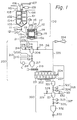
- a machine for solid phase polymerization comprises: a supplying system 100 for pre- crystallizing particles of a synthetic polymer and for supplying them; a reaction system 200 wherein the particles of a synthetic polymer fed from the supplying system 100 are subjected to a solid phase polymerization under vacuum so that the degree of polymerization of the particles is increased; and a system 300 for discharging the particles of a synthetic polymer from the reaction system.
- a pre-crystallizer 101 formed by a vertical vessel has a plurality of agitating bars 102 fixed on a hollow vertical spindle 103.
- the hollow vertical spindle 103 has an elongated hole 104 axially extending therein and connected to an opening 105 for blowing hot air located at the lower end thereof.
- the upper end of the hollow vertical spindle 103 is rotatably supported by a conventional bearing box 106 and connected to a rotary coupling (not shown) communicating with a hot air conduit 107, and the vertical spindle 103 is rotated about a vertical axis by an electric motor 109 via gears or chains.
- the hot air conduit 107 is supplied with hot air from a heat source (not shown), and the hot air is blown through the lower opening 105 toward the bottom of the pre-crystallizer 101.
- An exit 108 for discharging hot air is formed on the upper portion of the pre-crystallizer 101, and in some cases, the exit 108 may be communicated with the heat source via a recirculating conduit (not shown) so that the discharged hot air is recirculated.
- the pre-crystallizer 101 has a port 110 for supplying chips formed at the upper portion thereof and a port 111 for discharging chips formed at the bottom thereof.
- a beater 112 is disposed at a location beneath the pre-crystallizer 101 and comprises a basket 114 rotatable about a horizontal axis by means of an electric motor 119.
- a plurality of movable rods 113 horizontally projecting from the rotary basket 114 are arranged along two circles which are coaxial with each other about the horizontal axis.
- the front ends of the movable rods 113 are connected to two coaxial ring plates 113a and 113b.
- a plurality of stationary rods 115 fixed on a cover plate 118 are arranged along a circle coaxial with the above-mentioned circles so that they are inserted between the movable rods 113.
- the front ends of the stationary rods 115 are connected to a ring plate 115a.
- Reference numeral 117 denotes an outer wall of the beater 112.
- the discharge port 111 of the pre-crystallizer 101 and an entrance port 119 formed on the cover plate 118 of the beater 112 are communicated with each other by means of a communicating pipe 120 wherein an electrically movable shutter 121 is disposed.
- a vacuum reactor 201 which is the main apparatus of the reaction system 200 comprises: a horizontal vessel having a jacket 202 filled with a thermal medium for heating it formed at the outside thereof; and a horizontal shaft 207 connected to a drive electric motor 204, rotatably supported in the vessel and having a screw vane 203 helically arranged around the shaft 207.
- a series of vacuum reactors 201 having a similar construction to that explained above may be disposed in series.
- an intermediate pot 206 Between the beater 112 of the above-explained supplying system and the vacuum reactor 201, an intermediate pot 206, a supply hopper 217 and a screw feeder 219 for feeding chips continuously, are arranged in sequence.
- An apparatus for preheating chips may be arranged between the screw feeder 219 and the vacuum reactor 201, if such an apparatus is necessary to increase the temperature of the chips in the vacuum reactor 201.
- vacuum breakers 211 and 212 comprising particle shutters 207 and 208 located upwards and vacuum valves 209 and 210 located downwards are arranged.
- the intermediate pot 206 is connected to a conduit 214 for supplying nitrogen which accommodates an automatic valve 213 and a conduit for supplying vacuum which also accommodates an automatic valve 215.
- the supply hopper 217 has a conventional level detecting device 218 which detects the level of particles therein.
- a set of sequence circuits are arranged between the intermediate pot 206 and the supply hopper 217 via a 'controller C, so that first the level detecting device 218 detects the fact that the level of particles in the supply hopper 217 lowers to a predetermined level and then the automatic valves 213 and 215 and the vacuum breakers 211 and 212 are actuated in order to feed a certain amount of particles into the supply hopper 217.
- a tank (not shown) having a sufficient volume to continuously receive chips discharged from the beater 112 and to store them therein may be disposed between the beater and the uppermost vacuum breaker 211.
- the discharge system 300 will now be explaIned referring to rig. 1.
- a storage pot 320, an intermediate pot 321 and a cooling tank 332 for ceasing further crystallization of produced chips are successively arranged beneath the vacuum reactor 201.
- the intermediate pot 321 has a vacuum breaker 326 comprising a particle shutter 322 and a vacuum valve 324 disposed at the entrance thereof and a vacuum breaker 327 comprising a particle shutter 322 and a vacuum valve 325 disposed at the exit thereof as the intermediate pot 206 does.
- the intermediate pot 321 is connected to a conduit 329 for supplying nitrogen which includes an atuomatic valve 328 and is also connected to a conduit 331 using a vacuum which includes an automatic valve 330.
- a rotary valve 333 for controlling the discharge of the produced chips is disposed at the discharge side of the cooling tank 332.
- Reference numeral 334 denotes a steam ejector communicated with the vacuum reactor 201 via a vacuum conduit 335.
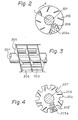
- the screw vane 203 is helically secured to the periphery of the horizontal rotatable shaft 207 and has a such a size, that the circumference of the screw vane 203 is located close to the inner surface of the vacuum reactor 201 or is in contact with the inner surface.
- the entire surface of the screw vane 203 has a multiplicity of small through-apertures 203 formed therein, only a part of which are illustrated in Fig. 2.
- a plurality of scrapers 206 disposed at radially outside locations of the screw vane 203 axially extend across spaces called screw grooves 205 and due formed between the adjacent portions of screw vane 203.
- chips which, for example, have an I.V., i.e., intrinsic viscosity, of 0.6 are supplied continuously or intermittently from a storage tank (not shown) to the pre-crystallizer 101 of the supplying system 100.
- the chips are heated to a temperature, for example, of between 130 and 180°C for polyethylene terephthalate, by means of hot air blown through the opening 105 formed at the lower end of the rotatable vertical spindle 103 while they are agitated by means of the agitating bars 102 fixed on the rotatable vertical spindle 103, and accordingly, they are uniformly heated and dried and the preliminary crystallization of the chips are effected.
- the distance of the crystallization from the surface of chips i.e., crystallized depth of chips be at least 40 ⁇ m. If a crystallized depth of at least 40,um is made in the chips at a temperature mentioned above, the sticking of the chips in the subsequent polymerization process wherein they are subjected to a reaction temperature of, for example, between 150 and 230°C can be avoided.
- a large quantity of stuck chips may be created, however such stuck chips created through the preliminary crystallization procedure are different from those created through the solid phase polymerization and can be separated from each other when a slight shearing force is applied.
- the beater 112 is disposed successive to the pre-crystallizer 101.
- the chips which have been crystallized to a predetermined depth in the pre-crystallizer 101 are introduced into a basket which is rotating at a high speed about the horizontal axis through the communicating pipe 120 and the entrance port 119 of the beater 112 by means of the actuation of the shutter 121.
- the chips introduced within the basket 114 are exposed to a shearing force when they pass by the movable rods 113 rotating with the basket 114 and the stationary rods 115 located between the movable rods 113, and accordingly, the stuck chips are completely separated from each other into individual chips.
- the automatic valve 213 When the level detecting device 218 mounted on the supply hopper 217 disposed beneath the beater 112 detects the fact that the level of chips in the supply hopper 217 is lower than a predetermined level, the automatic valve 213 is actuated to open by a detecting signal, and therefore, nitrogen gas is supplied into the intermediate pot 206. At this moment, all of the shutters 207 and 208, the vacuum valves 209 and 210, and the automatic valve 215 are closed.
- the automatic valve 213 is closed, and thereafter, the vacuum valve 209 is first open and then, for example after several seconds from the opening of the vacuum valve 209, the shutter 207 is open, so that chips drop into the intermediate pot 206.
- the shutter 207 is first closed, and then the vaccuum valve 209 is closed.
- the operation of the vacuum breaker 211 may be effected by means of a set of timers or by means of a level detecting device (not shown) mounted on the intermediate pot 206.
- the automatic valve 215 When the vacuum valve 209 is closed, the automatic valve 215 is open so that the inside of the intermediate pot 206 is brought to a vacuum state substantially the same as that in the vacuum reactor 201. After a predetermined vacuum level is .achieved, the automatic valve 21 is closed.
- the vacuum breaker 212 is actuated, more specifically, the vacuum valve 210 is open, and successively after several seconds, the shutter 208 is open so that the chips having been stored within the intermediate pot 206 are fed into the supply hopper 217. After the feed of the chips is completed, the shutter is closed, and then, the vacuum valve 210 is closed.
- the chips fed to the supply hopper 217 are then continuously fed to the vacuum reactor 201 by means of the screw feeder 219.
- the vacuum reactor 201 the chips are subjected to a high temperature of between 1 50 and 230°C, for example of 230°C, and a high vacuum of between 0.5 and 2 Torr, for example 1 Torr, and are gradually transferred while they are agitated and mixed, and after storage therein for a predetermined time period, they are polymerized in a solid phase.
- the inside of the vacuum reactor 201 is heated at a constant high temperature of between 1 50 and 230°C by means of the heating jacket 202 and is maintained at a high vacuum of between 0.5 and 2 Torr by means of the steam ejector 334, and the chips fed into the vacuum reactor 201 are axially transferred toward the exit thereof, i.e., to the right in Fig. 1, by means of the rotation of the screw vane 203.
- the screw vane 203 since the screw vane 203 has a multiplicity of small through-apertures 203a formed therein, only a part of the chips can be radially moved together with the screw vane 203 and the remaining part of the chips remain without substantially being transferred, and accordingly, the mixing of the chips is highly enhanced, and the feed of the chips as a whole becomes small. Furthermore, since scrapers 206 are formed between the facing portions of the screw vanes 203, a part of the chips are scraped and are then dropped while the scrapers 206 are rotated at certain angles during a quarter or a half a revolution from their lowermost locations.
- the chips which are scraped and drop, remain at substantially the same locations, in other words, the chips substantially do not move along the axial direction, and accordingly, the agitation of the chips in the same screw groove 205 effectively takes place and the mixing efficiency of the chips is high and the uniformity of the chips is guaranteed.
- the chips are transferred along the scrapers 206 in a thin layer, and accordingly, the surface area of the entire layered chips is increased. As a result, the diffusion of the moisture involved in the chips can be effectively achieved, and the reaction speed is also increased.
- the chips are gradually moved axially toward the exit thereof, i.e., to the right in Fig. 1 while they are agitated and mixed, and during this transferring process, the degree of the polymerization of the chips is gradually increased due to the proceeding of the polymerizing reaction, and accordingly, after several hours, for example, after a time of between 4 and 8 hours elapse, the chips which have obtained a desired degree of polymerization reach the exit of the vacuum crystallizer from where they are discharged.
- the scrapers 206 are arranged in such a manner that they slightly incline toward the rotational direction denoted by arrow A of the screw vane 203 by an angle ⁇ from the radial direction denoted by line r so that chips can be scraped easily and so that the scraped chips can drop rather rapidly.
- the area and the number of the through-apertures 203a formed in the screw vane 203 are so selected that the passing of the chips therethrough and the flow of gas therethrough, i.e., the suction of the vacuum, can be appropriate.
- to further decrease the feeding speed of chips in the vacuum reactor 201 and to increase the mixing of chips as illustrated in Fig.
- notches 203' may be formed at the periphery of the screw vane 203 as illustrated in Fig. 3. It is also preferable that an apparatus (not shown) for heating chips is arranged between the screw feeder 219 and the vacuum reactor 201, so that the chips are pre-heated to a certain temperature and then are supplied into the vacuum reactor 201.
- the reaction system according to the present invention, mixing of chips can be facilitated and the surface of a mass of chips can effectively be exposed to the crystallizing atmosphere, and accordingly, the reaction time can be shortened and the produced chips having a uniform and superior quality can be stably obtained.
- the chips are discharged as follows.
- the shutters 322 and 323, the vacuum valves 324 and 325, and the automatic valves 328 and 330 are all in their closed positions, and then, the automatic valve 330 is first open so that the intermediate pot 321 is brought into vacuum condition substantially the same as that in the vacuum reactor 201.
- the automatic valve 330 is closed, and then, the vacuum valve 324 is open, and after several seconds, the shutter 322 is open so that chips which have been stored in the storage pot 320 are dropped into the intermediate pot 321.
- the shutter 322 is first open, and then, after several seconds, the vacuum valve 324 is closed.
- the automatic valve 328 is open so that nitrogen gas is introduced into the intermediate pot 321 which is thus exposed to an atmosphere of nitrogen instead of a vacuum.
- the vacuum valve 325 and then the shutter 323 are successively open so that the chips which have been in the intermediate pot 321 are discharged into the cooling tank 332.
- the shutter 323 is closed, and after several seconds elapse, the vacuum valve 325 is closed. Procedures similar to those explained above are repeated, and accordingly, the chips which have been stored in the storage pot 320 are intermittently discharged into the cooling tank 332.
- the discharge of chips can be controlled by utilizing timers by which a series of a predetermined control program are carried out. However, other means for controlling the program may be used in place of the timers.
- a level detecting device may be mounted on the storage pot 320 so that the detecting device detects the fact that the level of chips in the storage pot 320 reaches a predetermined level in order to actuate the vacuum breaker 326.
- the intermediate pots with vacuum breakers comprising shutters and vacuum valves located at the supply and discharge sides thereof are arranged in the present invention, problems in that chips are clogged within the vacuum valves and in that accordingly the seal ability of the valves are decreased can be prevented from occurring, and therefore, the supply and discharge of chips can take place smoothly for a long period.
- the pre-crystallizer may be a horizontal agitating type
- the beater may be a centrifugal filter type
- a pre-treatment apparatus comprising a pre-crystallizer and a beater connected to the pre-crystallizer is disposed in a supplying system of a machine for solid phase polymerization.
- chips of a prepolymer are once preliminarily dried and preliminarily crystallized before they are supplied into the vacuum dryer in a reaction system wherein they are subjected to a solid phase polymerization, and then, they are introduced into a beater where stuck chips which have been stuck to each other through the preliminary crystalization are separated from each other into separate chips.
- the shutter of the present invention has such a function to shut out the flow of particles but is not required to have a seal ability against any fluid.
- the shutter may be a slide type plate whose sides are supported by U-shaped guides as is generally utilized in this field.
- a rotary feeder or a screw feeder which can shut out particles may be used as a shutter of the present invention.
- the valve i.e., vacuum valve
- the valve must have a function to shut out the flow of fluid and must be a valve having a superior seal ability and is utilized for shutting the vacuum.
- the construction of the valve is not limited.
- the functions of the shutter and the vacuum valve of the present invention are exlained above, and with respect to the sealing ability between the inside of the passage and the outside of the passage, the vacuum valve naturally must have sealing ability and the shutter, especially that designated by 208 or 322 and located at a position near the vacuum valve must have a superior sealing ability similar to that of the vacuum valve.
- the operational relationship between the shutter and the vacuum valve is such that, after either the shutter or the vacuum valve is open or closed, the remaining vacuum valve or shutter is open or closed, and accordingly, the clogging of chips between the vacuum valve can be prevented completely.
Landscapes
- Chemical & Material Sciences (AREA)
- Organic Chemistry (AREA)
- Chemical Kinetics & Catalysis (AREA)
- Health & Medical Sciences (AREA)
- Medicinal Chemistry (AREA)
- Polymers & Plastics (AREA)
- Other Resins Obtained By Reactions Not Involving Carbon-To-Carbon Unsaturated Bonds (AREA)
- Polyesters Or Polycarbonates (AREA)
Claims (3)
Applications Claiming Priority (6)
| Application Number | Priority Date | Filing Date | Title |
|---|---|---|---|
| JP9/80 | 1980-01-04 | ||
| JP780A JPS56112935A (en) | 1980-01-04 | 1980-01-04 | Solid-phase polymerizer |
| JP7/80 | 1980-01-04 | ||
| JP980A JPS56112936A (en) | 1980-01-04 | 1980-01-04 | Continuous solid-phase polymerization apparatus for powdered synthetic polymer |
| JP11467080A JPS5741567A (en) | 1980-08-22 | 1980-08-22 | Continuous vacuum drying equipment |
| JP114670/80 | 1980-08-22 |
Publications (2)
| Publication Number | Publication Date |
|---|---|
| EP0031968A1 EP0031968A1 (de) | 1981-07-15 |
| EP0031968B1 true EP0031968B1 (de) | 1984-06-13 |
Family
ID=27274265
Family Applications (1)
| Application Number | Title | Priority Date | Filing Date |
|---|---|---|---|
| EP80108262A Expired EP0031968B1 (de) | 1980-01-04 | 1980-12-31 | Vorrichtung für die Festphasen-Polymerisation |
Country Status (3)
| Country | Link |
|---|---|
| US (1) | US4370302A (de) |
| EP (1) | EP0031968B1 (de) |
| DE (1) | DE3068277D1 (de) |
Families Citing this family (62)
| Publication number | Priority date | Publication date | Assignee | Title |
|---|---|---|---|---|
| JPS6045353U (ja) * | 1983-08-31 | 1985-03-30 | 株式会社 ほくさん | ポリアセチレン膜製造装置 |
| JPS63234079A (ja) * | 1986-10-23 | 1988-09-29 | Yokohama Rubber Co Ltd:The | 一液型シーラントの製造方法 |
| DE3841671C1 (de) * | 1988-12-10 | 1989-10-26 | Maschinenfabrik Hennecke Gmbh, 5090 Leverkusen, De | |
| FR2678927B1 (fr) * | 1991-07-11 | 1993-11-19 | Maroc Chimie | Procede et installation de production de triple superphosphate (tsp) granule. |
| DE4227542A1 (de) * | 1992-08-20 | 1994-02-24 | Werner Kempter | Vorrichtung zur Herstellung eines vernetzten extrudierten Produktes |
| CN1100653C (zh) * | 1994-10-20 | 2003-02-05 | 威廉·海德里希真空设备两合公司 | 可浇注液态介质的连续混合脱气的方法和装置 |
| US5599507A (en) * | 1994-11-09 | 1997-02-04 | Shaw; Gordon | Reactor apparatus for preparing a polymeric material |
| JPH1170588A (ja) * | 1997-08-29 | 1999-03-16 | Ykk Corp | 再生合成樹脂スライドファスナー用部品の製造方法 |
| GB9909630D0 (en) * | 1999-04-28 | 1999-06-23 | Zeneca Ltd | Reactor |
| DE10158793A1 (de) * | 2001-11-30 | 2003-06-26 | Zimmer Ag | Verfahren und Vorrichtung zur Herstellung von hochkondensierten Polyestern in der festen Phase |
| ITTO20020714A1 (it) * | 2002-08-09 | 2004-02-10 | Giuliano Cavaglia | Procedimento per la polimerizzazione continua di |
| ES2291741T3 (es) * | 2002-09-25 | 2008-03-01 | STARLINGER & CO. GESELLSCHAFT MBH | Procedimiento y dispositivo para incrementar la viscosidad intrinseca de un material de poliester mediante un polimerizacion de estado solido. |
| ITTO20021124A1 (it) * | 2002-12-24 | 2004-06-25 | Giuliano Cavaglia | Reattore e metodo per polimerizzare in continuo in fase solida il polietilentereftalato (pet). |
| ITMI20030048A1 (it) * | 2003-01-15 | 2004-07-16 | Vomm Chemipharma Srl | Procedimento per la polimerizzazione in fase solida del |
| DE102004010680A1 (de) * | 2004-03-04 | 2005-10-06 | Zimmer Ag | Verfahren zur Herstellung von hochkondensierten Polyestern in der festen Phase |
| DE102005013701A1 (de) | 2005-03-24 | 2006-09-28 | Krones Ag | Verfahren und Vorrichtung zur Dekontamination von Kunststoffflakes |
| DE102006027176B4 (de) * | 2005-08-26 | 2015-08-06 | Lurgi Zimmer Gmbh | Verfahren und Vorrichtung zur Verringerung des Acetaldehydgehaltes von Polyestergranulat sowie Polyestergranulat |
| DE102006012587B4 (de) * | 2006-03-16 | 2015-10-29 | Lurgi Zimmer Gmbh | Verfahren und Vorrichtung zur Kristallisation von Polyestermaterial |
| CA2650610A1 (en) * | 2006-04-28 | 2007-11-08 | Wellman, Inc. | Methods for making polyester resins in falling film melt polycondensation reactors |
| CN101443103B (zh) * | 2006-05-11 | 2012-06-27 | 阿卡费尔工程有限公司 | 固相中聚合物连续聚合的方法和设备 |
| BRPI0714188A2 (pt) * | 2006-07-11 | 2012-12-25 | Wellman Inc | catalisador de polimerizaÇço de fase sàlida compàsito |
| ITTO20070084A1 (it) | 2007-02-06 | 2008-08-07 | K & E Srl | Dispositivi di miscelazione radiale per reattori inclinati rotanti. |
| US8334468B2 (en) | 2008-11-06 | 2012-12-18 | Covidien Ag | Method of switching a cordless hand-held ultrasonic cautery cutting device |
| US9017355B2 (en) | 2007-12-03 | 2015-04-28 | Covidien Ag | Battery-powered hand-held ultrasonic surgical cautery cutting device |
| US9314261B2 (en) | 2007-12-03 | 2016-04-19 | Covidien Ag | Battery-powered hand-held ultrasonic surgical cautery cutting device |
| US8061014B2 (en) | 2007-12-03 | 2011-11-22 | Covidien Ag | Method of assembling a cordless hand-held ultrasonic cautery cutting device |
| US9107690B2 (en) | 2007-12-03 | 2015-08-18 | Covidien Ag | Battery-powered hand-held ultrasonic surgical cautery cutting device |
| US8419757B2 (en) | 2007-12-03 | 2013-04-16 | Covidien Ag | Cordless hand-held ultrasonic cautery cutting device |
| US9630353B2 (en) | 2012-05-31 | 2017-04-25 | Mohawk Industries, Inc. | Method of manufacturing bulked continuous filament |
| US9636860B2 (en) | 2012-05-31 | 2017-05-02 | Mohawk Industries, Inc. | Method of manufacturing bulked continuous filament |
| US10538016B2 (en) | 2012-05-31 | 2020-01-21 | Aladdin Manufacturing Corporation | Methods for manufacturing bulked continuous carpet filament |
| US10532495B2 (en) | 2012-05-31 | 2020-01-14 | Aladdin Manufacturing Corporation | Methods for manufacturing bulked continuous filament from recycled PET |
| US11045979B2 (en) | 2012-05-31 | 2021-06-29 | Aladdin Manufacturing Corporation | Methods for manufacturing bulked continuous filament from recycled PET |
| US9630354B2 (en) | 2012-05-31 | 2017-04-25 | Mohawk Industries, Inc. | Method of manufacturing bulked continuous filament |
| US8597553B1 (en) | 2012-05-31 | 2013-12-03 | Mohawk Industries, Inc. | Systems and methods for manufacturing bulked continuous filament |
| US10695953B2 (en) | 2012-05-31 | 2020-06-30 | Aladdin Manufacturing Corporation | Methods for manufacturing bulked continuous carpet filament |
| US9636845B2 (en) | 2012-05-31 | 2017-05-02 | Mohawk Industries, Inc. | Method of manufacturing pet nurdles |
| US10487422B2 (en) | 2012-05-31 | 2019-11-26 | Aladdin Manufacturing Corporation | Methods for manufacturing bulked continuous filament from colored recycled pet |
| US10368898B2 (en) | 2016-05-05 | 2019-08-06 | Covidien Lp | Ultrasonic surgical instrument |
| US10751915B2 (en) | 2016-11-10 | 2020-08-25 | Aladdin Manufacturing Corporation | Polyethylene terephthalate coloring systems and methods |
| ES3005844T3 (en) | 2017-01-30 | 2025-03-17 | Aladdin Mfg Corp | Systems and methods for manufacturing items from colored recycled pet |
| US11279071B2 (en) | 2017-03-03 | 2022-03-22 | Aladdin Manufacturing Corporation | Method of manufacturing bulked continuous carpet filament |
| CN111093924A (zh) | 2017-09-15 | 2020-05-01 | 美国阿拉丁制造公司 | 聚对苯二甲酸乙二醇酯着色方法和用于制造膨化变形地毯长丝的系统 |
| US11259832B2 (en) | 2018-01-29 | 2022-03-01 | Covidien Lp | Ultrasonic horn for an ultrasonic surgical instrument, ultrasonic surgical instrument including the same, and method of manufacturing an ultrasonic horn |
| US11246617B2 (en) | 2018-01-29 | 2022-02-15 | Covidien Lp | Compact ultrasonic transducer and ultrasonic surgical instrument including the same |
| US11246621B2 (en) | 2018-01-29 | 2022-02-15 | Covidien Lp | Ultrasonic transducers and ultrasonic surgical instruments including the same |
| US11229449B2 (en) | 2018-02-05 | 2022-01-25 | Covidien Lp | Ultrasonic horn, ultrasonic transducer assembly, and ultrasonic surgical instrument including the same |
| US10582944B2 (en) | 2018-02-23 | 2020-03-10 | Covidien Lp | Ultrasonic surgical instrument with torque assist feature |
| US11242622B2 (en) | 2018-07-20 | 2022-02-08 | Aladdin Manufacturing Corporation | Bulked continuous carpet filament manufacturing from polytrimethylene terephthalate |
| US12343903B2 (en) | 2019-06-05 | 2025-07-01 | Aladdin Manufacturing Corporation | Methods for manufacturing bulked continuous carpet filament |
| US11478268B2 (en) | 2019-08-16 | 2022-10-25 | Covidien Lp | Jaw members for surgical instruments and surgical instruments incorporating the same |
| US12023065B2 (en) | 2019-09-03 | 2024-07-02 | Covidien Lp | Bi-stable spring-latch connector for ultrasonic surgical instruments |
| US11666357B2 (en) | 2019-09-16 | 2023-06-06 | Covidien Lp | Enclosure for electronics of a surgical instrument |
| CN110548472B (zh) * | 2019-10-11 | 2021-08-13 | 江西抚州新兴化工有限公司 | 一种节能型智能反应釜防残留装置 |
| US12004769B2 (en) | 2020-05-20 | 2024-06-11 | Covidien Lp | Ultrasonic transducer assembly for an ultrasonic surgical instrument |
| US11617599B2 (en) | 2020-10-15 | 2023-04-04 | Covidien Lp | Ultrasonic surgical instrument |
| US12426912B2 (en) | 2021-06-17 | 2025-09-30 | Covidien Lp | Surgical instruments, systems, and methods for frequency dithering control functionality |
| US11717312B2 (en) | 2021-10-01 | 2023-08-08 | Covidien Lp | Surgical system including blade visualization markings |
| CN114214735B (zh) * | 2021-11-19 | 2023-08-04 | 东华大学 | 一种线性无机聚合物溶胶纺丝液批量化制备装置 |
| CN115253977A (zh) * | 2022-08-23 | 2022-11-01 | 海安县恒业制丝有限公司 | 一种化纤工程尼龙6切片纺丝聚合反应器及其生产工艺 |
| CN116059948B (zh) * | 2023-01-20 | 2023-07-25 | 浙江归砚健康科技有限公司 | 一种植物精油微胶囊的包埋方法及微胶囊乳剂的制备装置 |
| EP4534188A1 (de) * | 2023-10-06 | 2025-04-09 | Carbon Upcycling Technologies Inc. | Schraubenreaktor zur kohlenstoffsequestrierung |
Citations (4)
| Publication number | Priority date | Publication date | Assignee | Title |
|---|---|---|---|---|
| FR1403325A (fr) * | 1963-07-22 | 1965-06-18 | Monsanto Co | Procédé et appareil pour la production de hauts polymères, en particulier du typedes polyesters et polyamides |
| FR2076951A5 (de) * | 1970-01-31 | 1971-10-15 | Buss Ag | |
| US4100142A (en) * | 1972-09-13 | 1978-07-11 | Fiber Industries, Inc. | Polyester process and product |
| FR2392319A1 (fr) * | 1977-05-25 | 1978-12-22 | Saarbergwerke Ag | Procede d'alimentation continue et reguliere de particules solides dans un appareil sous pression |
Family Cites Families (6)
| Publication number | Priority date | Publication date | Assignee | Title |
|---|---|---|---|---|
| US2080542A (en) * | 1933-09-15 | 1937-05-18 | Duisburger Kupferhuette | Conveyer |
| US2885246A (en) * | 1956-02-13 | 1959-05-05 | Phillips Petroleum Co | Feeding device for particulate solids |
| US3248180A (en) * | 1963-09-09 | 1966-04-26 | Du Pont | Polymer finisher apparatus |
| US3238122A (en) * | 1964-01-17 | 1966-03-01 | Socony Mobil Oil Co Inc | Hydrocarbon conversion process and apparatus useful therefor |
| JPS5222973B1 (de) * | 1971-04-24 | 1977-06-21 | ||
| US3779712A (en) * | 1971-11-26 | 1973-12-18 | Union Carbide Corp | Particulate solids injector apparatus |
-
1980
- 1980-12-30 US US06/221,204 patent/US4370302A/en not_active Expired - Lifetime
- 1980-12-31 DE DE8080108262T patent/DE3068277D1/de not_active Expired
- 1980-12-31 EP EP80108262A patent/EP0031968B1/de not_active Expired
Patent Citations (4)
| Publication number | Priority date | Publication date | Assignee | Title |
|---|---|---|---|---|
| FR1403325A (fr) * | 1963-07-22 | 1965-06-18 | Monsanto Co | Procédé et appareil pour la production de hauts polymères, en particulier du typedes polyesters et polyamides |
| FR2076951A5 (de) * | 1970-01-31 | 1971-10-15 | Buss Ag | |
| US4100142A (en) * | 1972-09-13 | 1978-07-11 | Fiber Industries, Inc. | Polyester process and product |
| FR2392319A1 (fr) * | 1977-05-25 | 1978-12-22 | Saarbergwerke Ag | Procede d'alimentation continue et reguliere de particules solides dans un appareil sous pression |
Also Published As
| Publication number | Publication date |
|---|---|
| DE3068277D1 (en) | 1984-07-19 |
| EP0031968A1 (de) | 1981-07-15 |
| US4370302A (en) | 1983-01-25 |
Similar Documents
| Publication | Publication Date | Title |
|---|---|---|
| EP0031968B1 (de) | Vorrichtung für die Festphasen-Polymerisation | |
| AU2008286673B2 (en) | Method and apparatus for the processing of plastic material | |
| KR100287605B1 (ko) | 폴리머결정을위한시스템 | |
| EP2349665B1 (de) | Verarbeitunsanlage, aufweisend ein gesteuertes zufuhrsystem für thermoplastische materialien | |
| US9789640B2 (en) | Method and device for granulating plastics and/or polymers | |
| EP2445691B1 (de) | Systeme für kontinuierliche pelletierung, trocknung und beutelverpackung mit erhöhtem durchsatz | |
| KR20040014553A (ko) | 하우징에 지지되는 스크류를 충전하는 장치 및 이러한타입의 장치를 작동하는 방법 | |
| US4589215A (en) | Apparatus for after-treating polyolefin powder | |
| CN110799271B (zh) | 涂覆散装物料的设备和方法 | |
| US4451268A (en) | Dry acetylene generator | |
| CN110799272B (zh) | 涂覆散装物料的方法 | |
| US4512732A (en) | Heat treating of material in finely divided form | |
| WO2006067544A1 (en) | Fluid bed apparatus and method of operating such apparatus | |
| US4421703A (en) | Heat treating of material in finely divided form | |
| US3678984A (en) | Reaction vessel for chemical and physical reactions of viscous masses | |
| CN119015973B (zh) | 一种环状酯的生产设备 | |
| CN120054335A (zh) | 卧式双搅拌熔融反应釜 | |
| KR101311774B1 (ko) | 원료 혼합장치 | |
| JPH0987392A (ja) | 重縮合系高分子の連続製造装置及び製造方法 | |
| HK1059600B (en) | Heating-crystallizing device for thermoplastic polymer chip | |
| EP0249251A1 (de) | Warmebehandlung von Feinzerteiltem Material | |
| KR20240028842A (ko) | 스크류 컨베이어가 구비된 중합장치 | |
| SU1337026A1 (ru) | Способ кристаллизации сгущенного молока и аппарат дл его осуществлени | |
| US6642349B1 (en) | Batch type apparatus for production of liquid crystalline polymer, and method for continuous production of liquid crystalline polymer using the apparatus | |
| JPH03169611A (ja) | 押出機の原料供給装置 |
Legal Events
| Date | Code | Title | Description |
|---|---|---|---|
| PUAI | Public reference made under article 153(3) epc to a published international application that has entered the european phase |
Free format text: ORIGINAL CODE: 0009012 |
|
| AK | Designated contracting states |
Designated state(s): DE GB NL |
|
| 17P | Request for examination filed |
Effective date: 19811222 |
|
| GRAA | (expected) grant |
Free format text: ORIGINAL CODE: 0009210 |
|
| AK | Designated contracting states |
Designated state(s): DE GB NL |
|
| REF | Corresponds to: |
Ref document number: 3068277 Country of ref document: DE Date of ref document: 19840719 |
|
| PLBE | No opposition filed within time limit |
Free format text: ORIGINAL CODE: 0009261 |
|
| STAA | Information on the status of an ep patent application or granted ep patent |
Free format text: STATUS: NO OPPOSITION FILED WITHIN TIME LIMIT |
|
| 26N | No opposition filed | ||
| PGFP | Annual fee paid to national office [announced via postgrant information from national office to epo] |
Ref country code: GB Payment date: 19931001 Year of fee payment: 14 |
|
| PGFP | Annual fee paid to national office [announced via postgrant information from national office to epo] |
Ref country code: NL Payment date: 19931231 Year of fee payment: 14 Ref country code: DE Payment date: 19931231 Year of fee payment: 14 |
|
| PG25 | Lapsed in a contracting state [announced via postgrant information from national office to epo] |
Ref country code: GB Effective date: 19941231 |
|
| PG25 | Lapsed in a contracting state [announced via postgrant information from national office to epo] |
Ref country code: NL Effective date: 19950701 |
|
| GBPC | Gb: european patent ceased through non-payment of renewal fee |
Effective date: 19941231 |
|
| NLV4 | Nl: lapsed or anulled due to non-payment of the annual fee |
Effective date: 19950701 |
|
| PG25 | Lapsed in a contracting state [announced via postgrant information from national office to epo] |
Ref country code: DE Effective date: 19950901 |