EP0031047A2 - Rotor à excitation par aimant permanent pour une machine synchrone - Google Patents
Rotor à excitation par aimant permanent pour une machine synchrone Download PDFInfo
- Publication number
- EP0031047A2 EP0031047A2 EP80107436A EP80107436A EP0031047A2 EP 0031047 A2 EP0031047 A2 EP 0031047A2 EP 80107436 A EP80107436 A EP 80107436A EP 80107436 A EP80107436 A EP 80107436A EP 0031047 A2 EP0031047 A2 EP 0031047A2
- Authority
- EP
- European Patent Office
- Prior art keywords
- slots
- short
- circuit
- radial
- recesses
- Prior art date
- Legal status (The legal status is an assumption and is not a legal conclusion. Google has not performed a legal analysis and makes no representation as to the accuracy of the status listed.)
- Granted
Links
Images
Classifications
-
- H—ELECTRICITY
- H02—GENERATION; CONVERSION OR DISTRIBUTION OF ELECTRIC POWER
- H02K—DYNAMO-ELECTRIC MACHINES
- H02K1/00—Details of the magnetic circuit
- H02K1/06—Details of the magnetic circuit characterised by the shape, form or construction
- H02K1/22—Rotating parts of the magnetic circuit
- H02K1/27—Rotor cores with permanent magnets
- H02K1/2706—Inner rotors
- H02K1/272—Inner rotors the magnetisation axis of the magnets being perpendicular to the rotor axis
- H02K1/274—Inner rotors the magnetisation axis of the magnets being perpendicular to the rotor axis the rotor consisting of two or more circumferentially positioned magnets
- H02K1/2753—Inner rotors the magnetisation axis of the magnets being perpendicular to the rotor axis the rotor consisting of two or more circumferentially positioned magnets the rotor consisting of magnets or groups of magnets arranged with alternating polarity
- H02K1/276—Magnets embedded in the magnetic core, e.g. interior permanent magnets [IPM]
- H02K1/2766—Magnets embedded in the magnetic core, e.g. interior permanent magnets [IPM] having a flux concentration effect
- H02K1/2773—Magnets embedded in the magnetic core, e.g. interior permanent magnets [IPM] having a flux concentration effect consisting of tangentially magnetized radial magnets
-
- H—ELECTRICITY
- H02—GENERATION; CONVERSION OR DISTRIBUTION OF ELECTRIC POWER
- H02K—DYNAMO-ELECTRIC MACHINES
- H02K21/00—Synchronous motors having permanent magnets; Synchronous generators having permanent magnets
- H02K21/46—Motors having additional short-circuited winding for starting as an asynchronous motor
-
- Y—GENERAL TAGGING OF NEW TECHNOLOGICAL DEVELOPMENTS; GENERAL TAGGING OF CROSS-SECTIONAL TECHNOLOGIES SPANNING OVER SEVERAL SECTIONS OF THE IPC; TECHNICAL SUBJECTS COVERED BY FORMER USPC CROSS-REFERENCE ART COLLECTIONS [XRACs] AND DIGESTS
- Y10—TECHNICAL SUBJECTS COVERED BY FORMER USPC
- Y10T—TECHNICAL SUBJECTS COVERED BY FORMER US CLASSIFICATION
- Y10T29/00—Metal working
- Y10T29/49—Method of mechanical manufacture
- Y10T29/49002—Electrical device making
- Y10T29/49009—Dynamoelectric machine
- Y10T29/49012—Rotor
Definitions
- the invention relates to a permanent magnet-excited rotor for a synchronous machine, which has a short-circuit cage with short-circuit rings arranged on both end faces and whose laminated core secured against centrifugal force stresses preferably has radially extending slots for receiving the permanent magnets.
- Such a runner is known from DE-OS 24 12 307. With this rotor, the individual segments of the laminated core are held on the shaft by positive undercuts. The permanent magnets inserted in the radial slots are magnetized from the outside in this rotor after the short-circuit cage has been cast.
- the permanent magnets must be inserted into the slots in the axial direction.
- An introduction of the permanent magnets in the radial direction from the shaft opening is generally ruled out, since the radial length of the permanent magnets is usually greater than the diameter of the shaft opening.
- the permanent magnets must be inserted axially before the short-circuit cage and the short-circuit rings are made, since the slots are covered by the short-circuit rings. Permanent magnets inserted into the slots before the short-circuit cage is cast are demagnetized by the strong heat development when casting the short-circuit cage and must therefore be re-magnetized from the outside. Such a subsequent magnetization is not possible with higher-pole rotors (from 6-pole) and generally when using rare earth magnets.
- the invention has for its object to provide a permanent magnet rotor for a synchronous machine, in which a high strength of the laminated core against centrifugal stress is achieved in a simple manner and also the full magnetic force of the permanent magnets is maintained even in a short-circuit cage produced in the casting process.
- the slots on the outer circumference of the rotor are closed and alternately on a short-circuit ring or on both short-circuit rings Recesses are provided which open the slots in the axial direction. Due to the closed slots on the outer circumference, the individual laminated core segments are held together securely even with high centrifugal forces. Since the radial slots remain axially accessible due to the recesses in the short-circuit rings, the premagnetized permanent magnets can be inserted into the slots in the axial direction after the short-circuit cage has been cast. The full magnetic force of the permanent magnets is retained.
- the short-circuit rings are divided into segments, each segment extending from one slot to the next but one slot and the segments on the one end side in relation to the segments on the other end side in the circumferential direction are offset by an arc length corresponding to the distance between two slots, the full radial thickness of the laminated core can be used for the arrangement of the permanent magnets.
- a material saving in the manufacture of the short-circuit cage is achieved in that, with a radial length of the slots that is shorter than the radial thickness of the laminated core, the radial depth of the recesses is equal to the radial length of the slots, with both short-circuit rings being one of half Number of slots have a corresponding number of cutouts, are formed in a meandering shape and are offset from one another in the circumferential direction by a base length corresponding to the distance between two slots.
- the meander shape reduces the volume of the short-circuit rings and thus saves material.
- a saving of material and at the same time a simplification of the casting tool results from the fact that with a radial length of the slots which is shorter than the radial thickness of the laminated core, the radial depth of the recesses is equal to the radial length of the slots, with only one short-circuit ring corresponding to the number of slots Number of recesses is provided and the segment parts of the short-circuit ring projecting outwards between the recesses are connected to an inner ring.
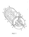
- Fig. 1 denotes a laminated rotor
- the laminated core 2 is provided with a short-circuit cage 3.
- the short-circuit rings 4 belonging to the short-circuit cage 3 are each divided into three segments 5.
- Recesses 6 are thus formed between the individual segments 5.
- Radially extending slots 7 are provided in the laminated core 2 in the area of the recesses 6. In the axial direction, the slots 7 extend over the full length of the laminated core.
- the slots 7 are closed by narrow webs 8. These narrow webs 8 can be stamped webs or can also consist of non-magnetic material, which is welded on afterwards. Permanent magnets are inserted into the radial slots 7. These permanent magnets can be inserted into the slots 7 between the cutouts 6 in the axial direction.
- the length of the segments 5 of the short-circuit rings 4 is such that these segments extend from one slot to the next but one.
- the segments 5 of the one short-circuit ring are offset in the circumferential direction relative to the segments 5 of the other short-circuit ring 4 by an arc length corresponding to the distance between two slots 7. In this way, a short circuit is achieved over the entire circumference of the rotor 1 despite the completely separate segments 5 of the two short-circuit rings 4.
- half of the permanent magnets are inserted into slots 7 from one side and half from the other.
- the described construction of the rotor creates the possibility to run the slots 7 on the outer circumference of the rotor 1 for reasons of strength and to be able to manufacture the short-circuit cage in the casting process without having to accept losses in terms of the magnetic properties of the permanent magnets.
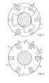
- the radial slots 7 extend only over part of the radial thickness of the laminated core 2.
- the radial depth of the recess 6 corresponds to the length of the slots 7.
- the short-circuit ring 4 can therefore be in the area between the slots 7 and the shaft 9 are continued. Since the short-circuit ring 4 has only a number of cutouts 6 corresponding to half the number of slots 7, the short-circuit ring can be designed in a meandering manner to save material.
- the short on the other side of the rotor Lock ring 4 is also meandering and offset in the circumferential direction by an arc length corresponding to the distance between two slots 7.
- Half of the permanent magnets are inserted from one side and the other into the slots 7 of the laminated core 2.
- a recess 10 is provided on the outer circumference of the rotor 1 above the slots 7.
- a rod made of non-magnetic material is welded into this recess 10. The rod must also be welded in before the magnets are inserted. The strong heating that occurs during autogenous welding would demagnetize the permanent magnets previously inserted in the slots 7 and thus impair the performance of the machine. Welding using an electron beam is also not possible after the permanent magnets have been inserted, since the electron beam is deflected by the magnetic field of the magnets and therefore no perfect welding is possible.
- the recesses 6 adapted in their radial depth to the slots 7 can all be provided on a short-circuit ring 4.
- the segment parts 11 of the short-circuit ring 4 projecting between the recess 6 are connected to an inner ring 12 surrounding the shaft 9.
- only one of the two short-circuit rings needs to be designed in this form, whereas the other short-circuit ring can be given its usual shape.
Landscapes
- Engineering & Computer Science (AREA)
- Power Engineering (AREA)
- Permanent Field Magnets Of Synchronous Machinery (AREA)
- Iron Core Of Rotating Electric Machines (AREA)
Applications Claiming Priority (2)
| Application Number | Priority Date | Filing Date | Title |
|---|---|---|---|
| DE2950008 | 1979-12-12 | ||
| DE19792950008 DE2950008A1 (de) | 1979-12-12 | 1979-12-12 | Dauermagneterregter laeufer fuer eine synchronmaschine |
Publications (3)
| Publication Number | Publication Date |
|---|---|
| EP0031047A2 true EP0031047A2 (fr) | 1981-07-01 |
| EP0031047A3 EP0031047A3 (en) | 1982-03-10 |
| EP0031047B1 EP0031047B1 (fr) | 1984-02-01 |
Family
ID=6088273
Family Applications (1)
| Application Number | Title | Priority Date | Filing Date |
|---|---|---|---|
| EP80107436A Expired EP0031047B1 (fr) | 1979-12-12 | 1980-11-27 | Rotor à excitation par aimant permanent pour une machine synchrone |
Country Status (4)
| Country | Link |
|---|---|
| US (1) | US4439704A (fr) |
| EP (1) | EP0031047B1 (fr) |
| JP (1) | JPS5694955A (fr) |
| DE (2) | DE2950008A1 (fr) |
Cited By (2)
| Publication number | Priority date | Publication date | Assignee | Title |
|---|---|---|---|---|
| EP0803962A1 (fr) * | 1996-04-23 | 1997-10-29 | Bamo Elettroutensili S.r.l. | Paquet de tÔles de rotor pour rotors à aimants permanents pour alternateurs ou similaires |
| DE19914021A1 (de) * | 1999-03-19 | 2000-12-07 | Siemens Ag | Mehrpoliger, permanenterregter Läufer für eine rotierende elektrische Maschine und Verfahren zur Herstellung eines solchen Läufers |
Families Citing this family (7)
| Publication number | Priority date | Publication date | Assignee | Title |
|---|---|---|---|---|
| FR2490018B1 (fr) * | 1980-09-09 | 1986-01-17 | Energy Conversion Devices Inc | Procede et dispositif pour etalonner les intervalles de bande d'alliages semi-conducteurs amorphes et alliages obtenus |
| US5068560A (en) * | 1990-12-26 | 1991-11-26 | Lynn Lundquist | Reduced current starting mechanism for three phase squirrel cage motors |
| DK157391A (da) * | 1991-09-06 | 1993-03-07 | Danfoss Flensburg Gmbh | Rotor til en elektrisk maskine |
| US6481090B1 (en) | 2001-06-25 | 2002-11-19 | Electric Boat Corporation | Installation and removal of energized permanent magnets in permanent magnet rotors |
| EP2928047A1 (fr) * | 2014-03-31 | 2015-10-07 | Siemens Aktiengesellschaft | Rotor à réluctance à stabilisation mécanique |
| CN105490418A (zh) * | 2016-01-20 | 2016-04-13 | 尚勤贵 | 自启动永磁同步电动机转子 |
| US20180205302A1 (en) * | 2017-01-19 | 2018-07-19 | Hamilton Sundstrand Corporation | Permanent magnet (pm) brushless machine with outer rotor |
Citations (2)
| Publication number | Priority date | Publication date | Assignee | Title |
|---|---|---|---|---|
| US2719931A (en) * | 1951-03-17 | 1955-10-04 | Kober William | Permanent magnet field generators |
| AT184978B (de) * | 1954-08-14 | 1956-03-10 | Franz Dipl Ing Geyer | Polrad für Synchronmaschinen |
Family Cites Families (7)
| Publication number | Priority date | Publication date | Assignee | Title |
|---|---|---|---|---|
| US1508152A (en) * | 1922-05-04 | 1924-09-09 | Gen Electric | Squirrel-cage winding for alternating-current motors |
| US1752104A (en) * | 1925-04-30 | 1930-03-25 | Gen Electric | Induction motor with variable reactance |
| US2543639A (en) * | 1949-10-29 | 1951-02-27 | Gen Electric | Rotor for synchronous induction motors |
| DE2412307A1 (de) * | 1974-03-14 | 1975-09-18 | Siemens Ag | Permanenterregte elektrische maschine |
| DE2608421C3 (de) * | 1976-03-01 | 1979-01-18 | Siemens Ag, 1000 Berlin Und 8000 Muenchen | Dauermagneterregter Innenläufer für eine Synchronmaschine |
| JPS5320515A (en) * | 1976-08-09 | 1978-02-24 | Hitachi Ltd | Rotor of permanent magnet synchronous motor |
| DE7726439U1 (de) * | 1977-08-25 | 1979-02-01 | Siemens Ag, 1000 Berlin Und 8000 Muenchen | Dauermagneterregte elektrische maschine |
-
1979
- 1979-12-12 DE DE19792950008 patent/DE2950008A1/de not_active Withdrawn
-
1980
- 1980-11-27 DE DE8080107436T patent/DE3066436D1/de not_active Expired
- 1980-11-27 EP EP80107436A patent/EP0031047B1/fr not_active Expired
- 1980-12-05 US US06/213,640 patent/US4439704A/en not_active Expired - Lifetime
- 1980-12-10 JP JP17522280A patent/JPS5694955A/ja active Pending
Patent Citations (2)
| Publication number | Priority date | Publication date | Assignee | Title |
|---|---|---|---|---|
| US2719931A (en) * | 1951-03-17 | 1955-10-04 | Kober William | Permanent magnet field generators |
| AT184978B (de) * | 1954-08-14 | 1956-03-10 | Franz Dipl Ing Geyer | Polrad für Synchronmaschinen |
Cited By (3)
| Publication number | Priority date | Publication date | Assignee | Title |
|---|---|---|---|---|
| EP0803962A1 (fr) * | 1996-04-23 | 1997-10-29 | Bamo Elettroutensili S.r.l. | Paquet de tÔles de rotor pour rotors à aimants permanents pour alternateurs ou similaires |
| DE19914021A1 (de) * | 1999-03-19 | 2000-12-07 | Siemens Ag | Mehrpoliger, permanenterregter Läufer für eine rotierende elektrische Maschine und Verfahren zur Herstellung eines solchen Läufers |
| DE19914021C2 (de) * | 1999-03-19 | 2002-01-31 | Siemens Ag | Mehrpoliger, permanenterregter Rotor für eine rotierende elektrische Maschine und Verfahren zur Herstellung eines solchen Läufers |
Also Published As
| Publication number | Publication date |
|---|---|
| DE3066436D1 (en) | 1984-03-08 |
| US4439704A (en) | 1984-03-27 |
| EP0031047A3 (en) | 1982-03-10 |
| DE2950008A1 (de) | 1981-06-19 |
| EP0031047B1 (fr) | 1984-02-01 |
| JPS5694955A (en) | 1981-07-31 |
Similar Documents
| Publication | Publication Date | Title |
|---|---|---|
| EP0729217B1 (fr) | Machine synchrone à excitation hybride | |
| DE2608421B2 (de) | Dauermagneterregter Innenläufer für eine Synchronmaschine | |
| DE112016001289T5 (de) | Motorrotor, einen Rotorkern umfassend, und ein Herstellungsverfahren hierfür | |
| EP0286905A1 (fr) | Moteur à courant continu à commutation électronique | |
| DE19818035A1 (de) | Transversalflußmaschine | |
| DE4033454A1 (de) | Permanentmagnetrotor | |
| DE102014101221A1 (de) | Rotor für einen Permanentmagnet-Motor, Verfahren zur Herstellung eines Rotors für einen Permanentmagnet-Motor sowie Permanentmagnet-Motor | |
| EP0043981A1 (fr) | Rotor excité par aimant permanent pour machine électrique | |
| EP0031047B1 (fr) | Rotor à excitation par aimant permanent pour une machine synchrone | |
| DE19900170A1 (de) | Permanentmagnetmotor | |
| DE1917149A1 (de) | Elektrischer Generator | |
| DE3026797A1 (de) | Kollektorloser gleichstrommotor | |
| DE2657892A1 (de) | Gleichstrom-dynamomaschine | |
| DE1160080B (de) | Elektromagnetisches System, insbesondere fuer einen Gleichstrommotor | |
| EP0809343B1 (fr) | Machine synchrone excité par aimant permanent | |
| EP3561999A1 (fr) | Machine électrique à flux magnétique variable | |
| DE1513857C3 (de) | Kleiner selbstanlaufender Wechselstromsynchronmotor | |
| DE2842517A1 (de) | Stator fuer eine dynamoelektrische gleichstrommaschine | |
| DE1763858C2 (de) | Elektrische Maschine | |
| DE102012218993A1 (de) | Läuferanordnung für eine permanentmagneterregte elektrische Maschine | |
| DE4418454A1 (de) | Außenläufer einer Synchronmaschine | |
| DE102013202006A1 (de) | Läuferanordnung für eine permanentmagneterregte elektrische Maschine | |
| DE2847921C2 (fr) | ||
| DE102012218980A1 (de) | Läuferanordnung für eine permanentmagneterregte elektrische Maschine | |
| EP3579383B1 (fr) | Rotor multipolaire à couple de rotation optimisé pour un moteur électrique |
Legal Events
| Date | Code | Title | Description |
|---|---|---|---|
| PUAI | Public reference made under article 153(3) epc to a published international application that has entered the european phase |
Free format text: ORIGINAL CODE: 0009012 |
|
| AK | Designated contracting states |
Designated state(s): DE FR GB IT NL |
|
| 17P | Request for examination filed |
Effective date: 19811028 |
|
| PUAL | Search report despatched |
Free format text: ORIGINAL CODE: 0009013 |
|
| AK | Designated contracting states |
Designated state(s): DE FR GB IT NL |
|
| ITF | It: translation for a ep patent filed |
Owner name: STUDIO JAUMANN |
|
| GRAA | (expected) grant |
Free format text: ORIGINAL CODE: 0009210 |
|
| AK | Designated contracting states |
Designated state(s): DE FR GB IT NL |
|
| REF | Corresponds to: |
Ref document number: 3066436 Country of ref document: DE Date of ref document: 19840308 |
|
| ET | Fr: translation filed | ||
| PGFP | Annual fee paid to national office [announced via postgrant information from national office to epo] |
Ref country code: FR Payment date: 19841120 Year of fee payment: 5 |
|
| PLBE | No opposition filed within time limit |
Free format text: ORIGINAL CODE: 0009261 |
|
| STAA | Information on the status of an ep patent application or granted ep patent |
Free format text: STATUS: NO OPPOSITION FILED WITHIN TIME LIMIT |
|
| PGFP | Annual fee paid to national office [announced via postgrant information from national office to epo] |
Ref country code: DE Payment date: 19850129 Year of fee payment: 5 |
|
| 26N | No opposition filed | ||
| PGFP | Annual fee paid to national office [announced via postgrant information from national office to epo] |
Ref country code: NL Payment date: 19851130 Year of fee payment: 6 |
|
| PG25 | Lapsed in a contracting state [announced via postgrant information from national office to epo] |
Ref country code: NL Effective date: 19870601 |
|
| NLV4 | Nl: lapsed or anulled due to non-payment of the annual fee | ||
| GBPC | Gb: european patent ceased through non-payment of renewal fee | ||
| PG25 | Lapsed in a contracting state [announced via postgrant information from national office to epo] |
Ref country code: FR Free format text: LAPSE BECAUSE OF NON-PAYMENT OF DUE FEES Effective date: 19870731 |
|
| PG25 | Lapsed in a contracting state [announced via postgrant information from national office to epo] |
Ref country code: DE Effective date: 19870801 |
|
| REG | Reference to a national code |
Ref country code: FR Ref legal event code: ST |
|
| PG25 | Lapsed in a contracting state [announced via postgrant information from national office to epo] |
Ref country code: GB Effective date: 19881118 |