EP0030484B1 - Appareil porte-sonde pour le contrôle des tubes d'un générateur de vapeur - Google Patents
Appareil porte-sonde pour le contrôle des tubes d'un générateur de vapeur Download PDFInfo
- Publication number
- EP0030484B1 EP0030484B1 EP80401589A EP80401589A EP0030484B1 EP 0030484 B1 EP0030484 B1 EP 0030484B1 EP 80401589 A EP80401589 A EP 80401589A EP 80401589 A EP80401589 A EP 80401589A EP 0030484 B1 EP0030484 B1 EP 0030484B1
- Authority
- EP
- European Patent Office
- Prior art keywords
- tubes
- probe
- carriage
- steam generator
- fingers
- Prior art date
- Legal status (The legal status is an assumption and is not a legal conclusion. Google has not performed a legal analysis and makes no representation as to the accuracy of the status listed.)
- Expired
Links
Images
Classifications
-
- F—MECHANICAL ENGINEERING; LIGHTING; HEATING; WEAPONS; BLASTING
- F22—STEAM GENERATION
- F22B—METHODS OF STEAM GENERATION; STEAM BOILERS
- F22B37/00—Component parts or details of steam boilers
- F22B37/002—Component parts or details of steam boilers specially adapted for nuclear steam generators, e.g. maintenance, repairing or inspecting equipment not otherwise provided for
- F22B37/003—Maintenance, repairing or inspecting equipment positioned in or via the headers
- F22B37/005—Positioning apparatus specially adapted therefor
Definitions
- the probe is carried by a device mounted mobile in the lower chamber of the generator into which all the tubes open.
- This device carries a guide tube which is brought in front of a beam tube and into which the probe is introduced. After checking a tube, the probe is removed from the tube, the device is moved a distance equal to the distance between two tubes and the probe is introduced into a new tube.
- the probe-carrying devices produced so far include expandable mandarins which are introduced and fixed in bundle tubes. But with these devices, the control of the tubes placed at the periphery of the beam is often difficult to achieve.
- a given device is only suitable for checking tubes having a given spacing; if one wishes to control the tubes of a steam generator in which the pitch of the tubes is different, one is obliged to modify the device fairly deeply. Finally, these devices are large and bulky.
- the probe carrier carriage is held in abutment by the arm against the tubular plate located in this chamber, the fingers or pins being engaged in generator tubes.
- the means for guiding the probe are then located in front of another tube of the generator which can be controlled.
- the step-by-step motor is then started, which makes it possible to move the carriage on the tube plate precisely and thus to bring the means for guiding the probe in front of another tube of the generator.
- the fingers are released from the tube plate, which makes it possible to pivot the carriage using the arm to bring these fingers and the means for guiding the probe in one direction. different. After putting the carriage back against the tube plate, the tubes which are in this direction can be checked.
- the carriage drive motor being a stepping motor, it is possible to record the movements of the carriage and know at all times the tube being checked.
- FR-A-2 394 374 describes transport equipment used to set up and remove the control device described above.
- This equipment comprises an arm or pole which is articulated on a support suitable for being fixed on an opening of the steam generator and carries a trolley which can at will be coupled to the control device or uncoupled from the latter.
- This equipment obviously does not overcome the drawbacks mentioned above.
- the subject of the present invention is a probe-carrying device for checking the tubes of a steam generator, which, on the contrary, does not have the said drawbacks.
- the apparatus comprises an arm articulated on a support suitable for being fixed on an opening of the steam generator, for example its access opening, and which carries a carriage and is characterized in that the arm is telescopic, by having one of its end elements mounted via a ball joint, or equivalent kinematic means, on the support while its other end is articulated on the carriage, and is subjected to the action elastic means tending to bring it into its position of maximum possible elongation, in that the carriage carries means for guiding a probe as well as drive means which are connected to a stepping motor carried by the carriage and are provided at their periphery with fingers or pins, and in that the means for guiding the probe and the fingers or pins are arranged in the same direction, the fingers or pins being separated from one another by distance equal to the pitch of the generator tubes or to a multiple of this not.
- the stepping motor can be an electric motor or a pneumatic or hydraulic motor which drives the carriage via a transmission.
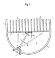
- a probe-carrying device which is designated in the drawing generally by the reference 8.
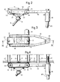
- the probe-carrying apparatus 8 comprises a telescopic support arm 9 which is controlled by a pneumatic spring and one of the end elements of which is fixed in a ball joint 10 mounted with the interposition of adjustable friction elements not shown, in a cap 11 fixed in the opening 7.
- the other end of the support arm 9 is connected by a ball joint 12 to a carriage 13.
- a carriage 13 In this carriage are mounted for rotation two shafts 14 spaced from one another and on which are fixed grooved or notched drums 15.
- a belt 16, the inner face of which is grooved or notched, passes over the two drums 15; this belt 16 carries fingers 17 which are arranged in the longitudinal median plane of the carriage and spaced from one another by a distance equal to the distance between two adjacent tubes 2.
- the output shaft of a stepping motor 18 mounted on the carriage 13 is connected to one of the shafts 14 and thus makes it possible to move the belt 16.
- One of the ends of the carriage 13 carries a support 19 whose axis is perpendicular to the plane of this carriage and in which is fitted a guide sheath 20 in which slides an eddy current probe 21 with its connecting cable.
- the support 19 is also arranged in the longitudinal median plane of the carriage.
- a locking finger (not shown) makes it possible to disengage the ball joint 12, that is to say to secure the carriage 13 and the telescopic arm 9, in the position in which these elements are located.
- the telescopic arm 9 is extended in the direction of the tubes 2 to be examined, so that the support 13 comes close to the tube plate 3, and the arm 9 is moved so as to engage fingers 17 in tubes 2 of the steam generator. We can then introduce the probe 21 into a tube 2 and proceed to check this tube.
- the tubes 2 are generally arranged in two different directions, most often perpendicular to each other. It is therefore necessary to modify the direction of movement of the carriage 13 to check all of the tubes.
- the arm 9 is slightly retracted which remains in the axial position by the action of the friction exerted on the ball joint 10 so as to release the fingers 17 of the orifices of the tubes 2 in which they were engaged, and so as to disengage the probe-carrying tube, the tube 9 is pivoted about its axis by the desired angle, the tube 9 is again extended so that the support 13 comes into abutment against the plate 3, and the ball joint is released 12.
- the support 13 can thus end up being applied against the plate 3 and the fingers 17 come to engage in the orifices of the tubes 2 directed in the second direction of the bundle of tubes.
- This maneuver is preferably done by first bringing the arm 9 into a position in which it is perpendicular to the tube plate 3; it then suffices to rotate this arm about its axis by an angle equal to that of the two directions of tubes, for example 90 ° if the tubes are oriented in two perpendicular directions.
- the device can be used regardless of the spacing of the tubes; it suffices for this to modify the spacing of the fingers 17 or to replace the belt 16 by a belt carrying fingers at the appropriate spacing, then to move the support 19 longitudinally.
Landscapes
- Physics & Mathematics (AREA)
- Engineering & Computer Science (AREA)
- High Energy & Nuclear Physics (AREA)
- Thermal Sciences (AREA)
- Mechanical Engineering (AREA)
- General Engineering & Computer Science (AREA)
- Monitoring And Testing Of Nuclear Reactors (AREA)
- Investigating Or Analyzing Materials By The Use Of Magnetic Means (AREA)
- Investigating Or Analyzing Materials By The Use Of Ultrasonic Waves (AREA)
- A Measuring Device Byusing Mechanical Method (AREA)
Priority Applications (1)
| Application Number | Priority Date | Filing Date | Title |
|---|---|---|---|
| AT80401589T ATE5694T1 (de) | 1979-11-30 | 1980-11-06 | Sondentraegervorrichtung zum ueberpruefen der rohre eines dampferzeugers. |
Applications Claiming Priority (2)
| Application Number | Priority Date | Filing Date | Title |
|---|---|---|---|
| FR7930022A FR2471026A1 (fr) | 1979-11-30 | 1979-11-30 | Appareil porte-sonde pour le controle des tubes d'un generateur de vapeur |
| FR7930022 | 1979-11-30 |
Publications (2)
| Publication Number | Publication Date |
|---|---|
| EP0030484A1 EP0030484A1 (fr) | 1981-06-17 |
| EP0030484B1 true EP0030484B1 (fr) | 1983-12-28 |
Family
ID=9232475
Family Applications (1)
| Application Number | Title | Priority Date | Filing Date |
|---|---|---|---|
| EP80401589A Expired EP0030484B1 (fr) | 1979-11-30 | 1980-11-06 | Appareil porte-sonde pour le contrôle des tubes d'un générateur de vapeur |
Country Status (10)
| Country | Link |
|---|---|
| US (1) | US4425296A (enExample) |
| EP (1) | EP0030484B1 (enExample) |
| JP (1) | JPS56138298A (enExample) |
| AT (1) | ATE5694T1 (enExample) |
| CA (1) | CA1146344A (enExample) |
| DE (1) | DE3066022D1 (enExample) |
| ES (1) | ES8501561A1 (enExample) |
| FR (1) | FR2471026A1 (enExample) |
| SU (1) | SU971121A3 (enExample) |
| ZA (1) | ZA807450B (enExample) |
Families Citing this family (15)
| Publication number | Priority date | Publication date | Assignee | Title |
|---|---|---|---|---|
| DE3122660C2 (de) * | 1981-06-06 | 1986-06-19 | Brown Boveri Reaktor GmbH, 6800 Mannheim | Einrichtung zur Inspektion und/oder zur Reparatur der Rohre eines Dampferzeugers einer Kernkraftanlage |
| FR2527308A1 (fr) * | 1982-05-19 | 1983-11-25 | Intercontrole Sa | Dispositif pour l'introduction d'un mobile de positionnement d'un organe sur une plaque tubulaire |
| US4814702A (en) * | 1984-05-31 | 1989-03-21 | Westinghouse Electric Corp. | Process for accurately determining the position of the edges of support plates in steam generators |
| FR2566309B1 (fr) * | 1984-06-22 | 1986-11-07 | Barras Provence | Dispositif pour positionner selectivement un outil porte par un vehicule se deplacant sur la plaque perforee d'un faisceau de tubes |
| FR2570314B1 (fr) * | 1984-09-20 | 1987-03-06 | Commissariat Energie Atomique | Robot porte-outil pour effectuer des interventions a l'interieur d'une enceinte possedant une ouverture d'acces |
| US4699750A (en) * | 1986-02-26 | 1987-10-13 | Westinghouse Electric Corp. | Apparatus for storage, retrieval and deployment of drag gages used in fuel assembly inspection |
| DE3743171A1 (de) * | 1987-12-19 | 1989-06-29 | Bbc Reaktor Gmbh | Einrichtung zur inspektion und/oder reparatur von in einem rohrboden eines waermetauschers endenden rohren |
| FR2632441B1 (fr) * | 1988-06-03 | 1992-05-15 | Framatome Sa | Procede et dispositif de controle des parois laterales d'un alveole de stockage d'un assemblage combustible |
| US5000681A (en) * | 1988-06-30 | 1991-03-19 | Westinghouse Electric Corp. | Apparatus and process for simultaneously positioning and oscillating a plurality of probes in the heat exchanger tubes of a nuclear steam generator |
| US5061176A (en) * | 1988-06-30 | 1991-10-29 | Westinghouse Electric Corp. | Apparatus and process for simultaneously positioning and oscillating a plurality of probes in the heat exchanger tubes of a nuclear steam generator |
| US5265129A (en) * | 1992-04-08 | 1993-11-23 | R. Brooks Associates, Inc. | Support plate inspection device |
| US5305356B1 (en) * | 1992-05-14 | 1998-09-01 | Brooks Support Systems Inc | Inspection device |
| US7314343B2 (en) * | 2002-07-22 | 2008-01-01 | Westinghouse Electric Co. Llc | Miniature manipulator for servicing the interior of nuclear steam generator tubes |
| US7762895B2 (en) * | 2006-10-02 | 2010-07-27 | Antonio Zamperla S.P.A. | Amusement apparatus with movable floor portion |
| JP5314609B2 (ja) * | 2010-01-27 | 2013-10-16 | 三菱重工業株式会社 | 水室内作業装置 |
Family Cites Families (8)
| Publication number | Priority date | Publication date | Assignee | Title |
|---|---|---|---|---|
| US3954136A (en) | 1973-03-30 | 1976-05-04 | Siemens Aktiengesellschaft | Pressurized-water reactor steam generator heat-exchanger tube access system |
| FR2309314A1 (fr) | 1974-12-05 | 1976-11-26 | Framatome Sa | Dispositif de positionnement selectif d'un organe sur une plaque tubulaire |
| FR2394374A2 (fr) * | 1977-06-15 | 1979-01-12 | Framatome Sa | Dispositif de positionnement selectif d'un organe sur une plaque tubulaire |
| DE2557992C3 (de) | 1975-12-22 | 1978-06-29 | Kraftwerk Union Ag, 4330 Muelheim | Prüfsystemträger zum Prüfen des AnschluBstutzenbereiches bei Druckbehältern, insbesondere Reaktordruckbehältern von Kernkraftwerken mit Ultraschall |
| DE2640055C3 (de) | 1976-09-06 | 1979-07-19 | Kraftwerk Union Ag, 4330 Muelheim | Rohrkrfimmermanipulator, insbesondere zur Ultraschallprüfung bei Kernreaktoranlagen |
| DE2831822C2 (de) | 1978-07-19 | 1980-04-24 | Kraftwerk Union Ag, 4330 Muelheim | Inspektionseinrichtung für ein Prüfgerät |
| US4192067A (en) * | 1978-10-23 | 1980-03-11 | Westinghouse Electric Corp. | Apparatus for cutting through a tube bundle |
| FR2448143A1 (fr) | 1979-02-05 | 1980-08-29 | Intercontrole Sa | Procede et dispositif pour retirer un porte-sonde de la chambre inferieure d'un echangeur de chaleur tubulaire verticale |
-
1979
- 1979-11-30 FR FR7930022A patent/FR2471026A1/fr active Granted
-
1980
- 1980-10-31 US US06/202,748 patent/US4425296A/en not_active Expired - Lifetime
- 1980-11-06 EP EP80401589A patent/EP0030484B1/fr not_active Expired
- 1980-11-06 AT AT80401589T patent/ATE5694T1/de not_active IP Right Cessation
- 1980-11-06 DE DE8080401589T patent/DE3066022D1/de not_active Expired
- 1980-11-25 SU SU803008200A patent/SU971121A3/ru active
- 1980-11-27 ES ES497175A patent/ES8501561A1/es not_active Expired
- 1980-11-27 JP JP16735680A patent/JPS56138298A/ja active Pending
- 1980-11-28 CA CA000365747A patent/CA1146344A/fr not_active Expired
- 1980-11-28 ZA ZA00807450A patent/ZA807450B/xx unknown
Also Published As
| Publication number | Publication date |
|---|---|
| ES497175A0 (es) | 1984-11-16 |
| FR2471026B1 (enExample) | 1985-02-08 |
| DE3066022D1 (en) | 1984-02-02 |
| FR2471026A1 (fr) | 1981-06-12 |
| CA1146344A (fr) | 1983-05-17 |
| ZA807450B (en) | 1981-11-25 |
| US4425296A (en) | 1984-01-10 |
| JPS56138298A (en) | 1981-10-28 |
| ATE5694T1 (de) | 1984-01-15 |
| SU971121A3 (ru) | 1982-10-30 |
| EP0030484A1 (fr) | 1981-06-17 |
| ES8501561A1 (es) | 1984-11-16 |
Similar Documents
| Publication | Publication Date | Title |
|---|---|---|
| EP0030484B1 (fr) | Appareil porte-sonde pour le contrôle des tubes d'un générateur de vapeur | |
| CA1101136A (fr) | Dispositif de positionnement selectif d'un organe sur une plaque tubulaire | |
| EP0178971B1 (fr) | Robot porte-outil pour effectuer des interventions à l'intérieur d'une enceinte possédant une ouverture d'accès | |
| EP0020272B1 (fr) | Porte-outil mobile pour travail sur une plaque tubulaire | |
| EP0014616B1 (fr) | Procédé et dispositif pour retirer de ou pour remettre en place dans la chambre inférieure d'un échangeur de chaleur tubulaire un porte-sonde | |
| EP0064436B1 (fr) | Dispositif d'introduction ou d'extraction d'organe dans un générateur de vapeur | |
| EP0104118B1 (fr) | Dispositif de raccordement déconnectable d'une grenouillère sur un bras esclave de télémanipulateur et support de déconnexion correspondant | |
| FR2644568A1 (fr) | Dispositif d'intervention, notamment pour le controle, l'inspection et la maintenance des echangeurs de chaleur | |
| FR2553890A1 (fr) | Appareil electromagnetique de manoeuvre de sondes | |
| FR2643135A1 (fr) | Vehicule d'exploration et de maintenance des tubes de generateurs de vapeur ou similaires | |
| EP0244282B1 (fr) | Dispositif d'alimentation à distance en pièces de forme cylindrique d'une machine automatique telle qu'une machine de bouchage de tubes d'un générateur de vapeur d'un réacteur nucléaire à eau sous pression | |
| FR2513927A1 (fr) | Tele-manipulateur d'intervention dans une boite a eau de generateur de vapeur | |
| EP0024991B1 (fr) | Dispositif de détection des défauts d'une plaque métallique au moyen de courants de Foucault, et procédé utilisant ce dispositif | |
| EP0281433B1 (fr) | Système d'intervention sur les tuyauteries primaires et la boîte à eau d'un générateur de vapeur centrale nucléaire | |
| FR2684228A1 (fr) | Appareil de maintenance avec commande a distance. | |
| EP0082159B1 (fr) | Dispositif pour positionner et inserer des rayons dans les trous d'un moyeu de roue a rayons | |
| FR2723661A1 (fr) | Installation pour la mise en place d'assemblages de combustible nucleaire | |
| FR2679370A1 (fr) | Dispositif d'inspection et d'intervention dans la partie secondaire d'un generateur de vapeur d'un reacteur nucleaire refroidi a l'eau. | |
| EP0292375B1 (fr) | Installation pour commander à distance la translation d'un organe tel qu'un outil de micromartelage dans un tube, notamment de générateur de vapeur | |
| CH623425A5 (en) | Process for the manufacture of a cluster guide for a nuclear reactor and tools for making use of this process | |
| FR2755239A1 (fr) | Procede et dispositif d'examen optique d'un element dispose a l'interieur d'un mecanisme de deplacement d'une barre de commande d'un reacteur nucleaire refroidi par de l'eau sous pression | |
| EP0342081A1 (fr) | Dispositif d'ancrage dans un alésage taraudé et machine de brossage incorporant un tel dispositif | |
| FR2741162A1 (fr) | Procede pour denuder une fibre optique ou un ruban de fibres optiques et appareil pour sa mise en oeuvre | |
| FR2563823A1 (fr) | Dispositif de levage de dalles, notamment de tampons pour boites de reseau | |
| FR2655032A1 (fr) | Conteneur ultrapropre de transfert d'une cassette dans une atmosphere de haute proprete et portable manuellement. |
Legal Events
| Date | Code | Title | Description |
|---|---|---|---|
| PUAI | Public reference made under article 153(3) epc to a published international application that has entered the european phase |
Free format text: ORIGINAL CODE: 0009012 |
|
| AK | Designated contracting states |
Designated state(s): AT BE CH DE GB IT LU NL SE |
|
| 17P | Request for examination filed |
Effective date: 19811116 |
|
| ITF | It: translation for a ep patent filed | ||
| GRAA | (expected) grant |
Free format text: ORIGINAL CODE: 0009210 |
|
| AK | Designated contracting states |
Designated state(s): AT BE CH DE GB IT LI LU NL SE |
|
| REF | Corresponds to: |
Ref document number: 5694 Country of ref document: AT Date of ref document: 19840115 Kind code of ref document: T |
|
| REF | Corresponds to: |
Ref document number: 3066022 Country of ref document: DE Date of ref document: 19840202 |
|
| PG25 | Lapsed in a contracting state [announced via postgrant information from national office to epo] |
Ref country code: LU Free format text: LAPSE BECAUSE OF NON-PAYMENT OF DUE FEES Effective date: 19841130 |
|
| PLBE | No opposition filed within time limit |
Free format text: ORIGINAL CODE: 0009261 |
|
| STAA | Information on the status of an ep patent application or granted ep patent |
Free format text: STATUS: NO OPPOSITION FILED WITHIN TIME LIMIT |
|
| 26N | No opposition filed | ||
| PGFP | Annual fee paid to national office [announced via postgrant information from national office to epo] |
Ref country code: AT Payment date: 19851114 Year of fee payment: 6 |
|
| PGFP | Annual fee paid to national office [announced via postgrant information from national office to epo] |
Ref country code: NL Payment date: 19851130 Year of fee payment: 6 |
|
| PG25 | Lapsed in a contracting state [announced via postgrant information from national office to epo] |
Ref country code: AT Effective date: 19861106 |
|
| PG25 | Lapsed in a contracting state [announced via postgrant information from national office to epo] |
Ref country code: NL Effective date: 19870601 |
|
| NLV4 | Nl: lapsed or anulled due to non-payment of the annual fee | ||
| GBPC | Gb: european patent ceased through non-payment of renewal fee | ||
| PG25 | Lapsed in a contracting state [announced via postgrant information from national office to epo] |
Ref country code: GB Effective date: 19881118 |
|
| PGFP | Annual fee paid to national office [announced via postgrant information from national office to epo] |
Ref country code: BE Payment date: 19901031 Year of fee payment: 11 |
|
| PGFP | Annual fee paid to national office [announced via postgrant information from national office to epo] |
Ref country code: SE Payment date: 19901119 Year of fee payment: 11 |
|
| PGFP | Annual fee paid to national office [announced via postgrant information from national office to epo] |
Ref country code: DE Payment date: 19901213 Year of fee payment: 11 |
|
| PGFP | Annual fee paid to national office [announced via postgrant information from national office to epo] |
Ref country code: CH Payment date: 19910226 Year of fee payment: 11 |
|
| PG25 | Lapsed in a contracting state [announced via postgrant information from national office to epo] |
Ref country code: SE Effective date: 19911107 |
|
| PG25 | Lapsed in a contracting state [announced via postgrant information from national office to epo] |
Ref country code: LI Effective date: 19911130 Ref country code: CH Effective date: 19911130 Ref country code: BE Effective date: 19911130 |
|
| BERE | Be: lapsed |
Owner name: INTERCONTROLE Effective date: 19911130 |
|
| REG | Reference to a national code |
Ref country code: CH Ref legal event code: PL |
|
| PG25 | Lapsed in a contracting state [announced via postgrant information from national office to epo] |
Ref country code: DE Effective date: 19920801 |
|
| EUG | Se: european patent has lapsed |
Ref document number: 80401589.9 Effective date: 19920604 |