EP0029482A1 - Gas blast switch - Google Patents
Gas blast switch Download PDFInfo
- Publication number
- EP0029482A1 EP0029482A1 EP80104260A EP80104260A EP0029482A1 EP 0029482 A1 EP0029482 A1 EP 0029482A1 EP 80104260 A EP80104260 A EP 80104260A EP 80104260 A EP80104260 A EP 80104260A EP 0029482 A1 EP0029482 A1 EP 0029482A1
- Authority
- EP
- European Patent Office
- Prior art keywords
- cylinder
- piston
- switch
- push rod
- stroke
- Prior art date
- Legal status (The legal status is an assumption and is not a legal conclusion. Google has not performed a legal analysis and makes no representation as to the accuracy of the status listed.)
- Granted
Links
Images


Classifications
-
- H—ELECTRICITY
- H01—ELECTRIC ELEMENTS
- H01H—ELECTRIC SWITCHES; RELAYS; SELECTORS; EMERGENCY PROTECTIVE DEVICES
- H01H33/00—High-tension or heavy-current switches with arc-extinguishing or arc-preventing means
- H01H33/70—Switches with separate means for directing, obtaining, or increasing flow of arc-extinguishing fluid
- H01H33/88—Switches with separate means for directing, obtaining, or increasing flow of arc-extinguishing fluid the flow of arc-extinguishing fluid being produced or increased by movement of pistons or other pressure-producing parts
- H01H33/90—Switches with separate means for directing, obtaining, or increasing flow of arc-extinguishing fluid the flow of arc-extinguishing fluid being produced or increased by movement of pistons or other pressure-producing parts this movement being effected by or in conjunction with the contact-operating mechanism
- H01H33/91—Switches with separate means for directing, obtaining, or increasing flow of arc-extinguishing fluid the flow of arc-extinguishing fluid being produced or increased by movement of pistons or other pressure-producing parts this movement being effected by or in conjunction with the contact-operating mechanism the arc-extinguishing fluid being air or gas
Definitions
- the invention relates to a gas pressure switch with a movable contact piece fastened to the end of a push rod, which can be brought into and out of engagement with a stationary contact piece, and with a blowing nozzle which gives the free end of the movable contact piece and is fastened to the push rod.
- a gas pressure switch with a movable contact piece fastened to the end of a push rod, which can be brought into and out of engagement with a stationary contact piece, and with a blowing nozzle which gives the free end of the movable contact piece and is fastened to the push rod.
- a pump chamber containing extinguishing gas and enclosed by a cylinder, which can be pressurized in the course of a switch-off stroke, the cylinder being displaceably guided on a stationary supported piston.
- Such switches are known and, thanks to their simple design (stationary supported pistons), have also proven themselves, especially since the cylinder can also serve as a movable nominal current contact, which can serve in and out of engagement with a corresponding, stationary counter contact.
- the cylinder itself is fastened to the push rod via a flange or via the blowing nozzle, ie with the movable one Contact piece connected, which means that considerable masses must be accelerated, especially at the beginning of the switch-off stroke. This in turn requires a very powerful switch drive.
- the proposed gas pressure switch according to the invention is characterized in that the blowing nozzle is designed as the bottom of a second piston opposite the first piston, which can be displaced relative to the cylinder in this between two end positions, means being provided around the cylinder during a switch-off stroke in the same direction as the movable contact piece, but to move a smaller distance than this.
- the means for moving the cylinder in the same direction as the movable contact piece during a switch-off stroke, but for moving a smaller distance can be designed in the simplest embodiment as a drag connection between the blow nozzle designed as a piston and the cylinder itself.
- This towing connection can have two stops which are arranged at a distance from one another in the cylinder and which fix the end positions of the blowing nozzle with respect to the cylinder, which can be biased in the direction of the switch-off stroke by means of a spring.
- This spring which is tightened more during the switch-on stroke, also serves as an energy accumulator that supports the drive.
- the cylinder can also be coupled via a gearbox (lever, friction wheel or gearwheel gearbox) to the push rod which moves the movable contact piece and the blowing nozzle, which gearbox has a reducing effect in the direction of the cylinder.
- a gearbox lever, friction wheel or gearwheel gearbox
- the movement of the cylinder with respect to that of the push rod remains well defined in every phase of the switch-off stroke.
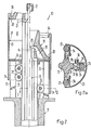
- the pressure gas switch 10 shown is shown in the left half of FIGS. 1-3 in the on position, in the right half in the off position, functionally corresponding components being identified by the same reference numerals.
- An electrically conductive support 11 carries a tubular insulating housing 12, only partially shown, in which the essential components of the switch are arranged and which contains an extinguishing gas under pressure, for example SF 6 .
- a pin-shaped contact piece 14 attached to the free end of a push rod 13 is in and out of engagement with a tubular, stationary by means of a drive, not shown, which moves the push rod 13 either in the direction of arrow 15 (switch-off stroke) or arrow 16 (switch-on stroke) arranged contact piece 17 can be brought.
- a blowing nozzle 18 is fastened by means not shown, which surrounds the movable contact piece 14 with its nozzle space 19 and is in front of it with its narrowest point 20.
- the inlets 21 of the blowing nozzle 18 are directly connected to a pump chamber 22.
- the circumference of the pump chamber 22 is delimited by a cylinder 23, which in turn is slidably guided on a pump piston 24.
- the pump piston 24 is firmly supported on the support 11 by means of several (at least two) columns 25.
- the blowing nozzle 18 is also slidably mounted in the cylinder 23 and thus also acts as a piston.
- a first stop 26 and a second stop 27 is formed on the inside of the cylinder 23 at the upper end thereof. These stops are intended to cooperate with the peripheral flange 28 of the blowing nozzle 18 and thus determine the extent of the relative movement of the blowing nozzle 18 in the cylinder 23. These stops 26, 27, together with the peripheral flange 28, form an effective towing connection between the push rod 13 and the cylinder 23.
- the cylinder 23 is biased in the direction of the switch-off stroke, and the springs 21 act as a force accumulator, which is coupled to the push rod 13 via the cylinder 23, the stop 26, the peripheral flange 28 and supports the drive at least at the beginning of the switch-off movement and for acceleration of the movable contact piece 14 contributes.
- the movable contact piece moves during the switch-off stroke 14 and with it the blowing nozzle 18 away from the fixed contact piece 17.
- the cylinder 23 also moves away from the fixed contact piece, but only until the stop 27 comes to rest on the stationary piston 24. Then the cylinder 23 stops, the peripheral flange 28 detaches from the stop 26, and now the blowing nozzle, which now acts as a piston, displaces the extinguishing gas from the remaining pump chamber until the position shown in FIG. 1 on the right is reached.
- the cylinder 23 has traveled a shorter distance than the switching stroke by the distance indicated by the dimensional arrow 31.
- the cylinder 23 initially stops and is only raised when the peripheral flange 28 of the blowing nozzle 18 strikes the stop 26, the compression springs 29 then being tensioned again.
- FIG. 1 While, as mentioned, in FIG. 1 the cylinder 23 is coupled to the push rod 13 via a towing connection, a gear is provided for this coupling in FIGS. 2 and 3, namely a force-locking in FIG. 2 and in FIG. 3 a positive gear.
- bulges 33 are formed on the circumferentially longitudinally extending sides with an outwardly convex cross section, which are each arranged opposite one of the columns 25 supporting the piston 24.
- the number of beads 33 (four are shown, but it could just as well be two or three) are attached to the inside of the cylinder 23 in its lower region pairs of inwardly extending bearing plates 34, the bearing plates 34 of a pair each encompassing a column 25 with play.
- Two pairs of smooth bevel gears 35, 36 are rotatably mounted on a pin 37 on each pair of bearing plates.
- the two bevel gears 35, 36 of a pair are arranged facing each other with their smaller diameters.
- the bevel gear 35 is firmly seated on the pin 37 rotatably mounted in the bearing plates 34, while the bevel gear 36 is freely rotatable on the pin 37.
- the pin 37 extending beyond the bevel gear 36 is under the action of a compression spring 38, so that the bevel gears 35, 36 are resiliently biased toward one another.
- the bevel gears 35, 36 roll on the one hand on the assigned, stationary column 25, on the other hand on the bead 33 formed on the push rod 13 and thus also act as rolling contacts between the push rod 13 and the relevant column 25, that is, between the movable one Contact piece 14 and the support 11.
- the stop 27 can also be provided in this embodiment — as indicated by dashed lines — via which the cylinder 23 is then by means of the peripheral flange 28 and under Ueberwin Extension of the frictional connection between the columns 25 and the push rod 13 on the one hand and the bevel gears 35, 36 on the other hand is pressed into its lowest position at the end of the switch-off stroke.
- a toothed rack 39 is attached to the stationary columns 25 and a toothed rack 40 is also attached to the sides of the push rod 13 opposite the columns 25.
- bearing brackets 41 are fastened to the inside of the cylinder, in each of which a gear 42 meshing both with the rack 39 and with the rack 40 is freely rotatable.
- the mode of operation of this embodiment largely corresponds to that of the embodiment according to FIG. 2 with the difference already mentioned that the coupling between the push rod 13 and the cylinder 23 is slip-free.
- springs can also be provided in the embodiments of FIGS. 2 and 3, which load the cylinder 23 in the direction of the switch-off stroke, and thus also serve as an energy store supporting the switch drive.
Landscapes
- Circuit Breakers (AREA)
- Driving Mechanisms And Operating Circuits Of Arc-Extinguishing High-Tension Switches (AREA)
- Percussion Or Vibration Massage (AREA)
- Glass Compositions (AREA)
- Vehicle Body Suspensions (AREA)
Abstract
Description
Die Erfindung betrifft einen Druckgasschalter mit einem am Ende einer Schubstange befestigten, beweglichen Kontaktstück, das in und ausser Eingriff mit einem ortsfesten Kontaktstück bringbar ist, und mit einer das freie Ende des beweglichen Kontaktstückes gebenden, an der Schubstange befestigten Blasdüse, deren Einlass mit einem, ein Löschgas enthaltenden und von einem Zylinder umschlossenen Pumpraum in Verbindung steht, der im Zuge eines Ausschalthubes unter Druck setzbar ist, wobei der Zylinder verschiebbar auf einem ortsfest abgestützten Kolben geführt ist.The invention relates to a gas pressure switch with a movable contact piece fastened to the end of a push rod, which can be brought into and out of engagement with a stationary contact piece, and with a blowing nozzle which gives the free end of the movable contact piece and is fastened to the push rod. is connected to a pump chamber containing extinguishing gas and enclosed by a cylinder, which can be pressurized in the course of a switch-off stroke, the cylinder being displaceably guided on a stationary supported piston.
Solche Schalter sind bekannt und haben sich dank ihrer einfachen Bauweise (ortsfest abgestützter Kolben) auch bewährt, zumal der Zylinder auch als beweglicher Nennstromkontakt dienen kann, der in und ausser Eingriff mit einem entsprechenden, ortsfest angeordneten Gegenkontakt dienen kann. Allerdings ist bei den bekannten Schaltern der Zylinder über einen Flansch oder über die Blasdüse selbst an der Schubstange befestigt, d.h. mit dem beweglichen Kontaktstück verbunden, was zur Folge hat, dass namentlich zu Beginn des Ausschalthubes erhebliche Massen zu beschleunigen sind. Dies erfordert wiederum einen sehr leistungsfähigen Schalterantrieb.Such switches are known and, thanks to their simple design (stationary supported pistons), have also proven themselves, especially since the cylinder can also serve as a movable nominal current contact, which can serve in and out of engagement with a corresponding, stationary counter contact. However, in the known switches, the cylinder itself is fastened to the push rod via a flange or via the blowing nozzle, ie with the movable one Contact piece connected, which means that considerable masses must be accelerated, especially at the beginning of the switch-off stroke. This in turn requires a very powerful switch drive.
Es ist daher ein Zweck der Erfindung, einen Schalter der eingangs genannten Art zu schaffen, bei dem die zu Beginn des Ausschalthubes zu beschleunigenden Massen erheblich reduziert sind, so dass selbst bei weniger leistungsfähigen Antrieben die Kontaktstücke innert kürzester Zeit die minimale Löschdistanz voneinander erreichen, ohne dass die Beblasung des Schaltlichtbogens an Intensität verlieren würde und ohne dass dem Zylinder seine weitere Funktion, gegebenenfalls als beweglichen Nennstromkontakt zu dienen, entzogen würde.It is therefore a purpose of the invention to provide a switch of the type mentioned, in which the masses to be accelerated at the beginning of the switch-off stroke are considerably reduced, so that even with less powerful drives, the contact pieces reach the minimum quenching distance from one another within a very short time, without that the blowing of the switching arc would lose intensity and without the cylinder's further function, possibly serving as a movable nominal current contact, being withdrawn.
Zu diesem Zweck ist der vorgeschlagene Druckgasschalter gemäss der Erfindung dadurch gekennzeichnet, dass die Blasdüse als Boden eines zweiten, dem ersten Kolben gegenüberliegenden Kolben ausgebildet ist, der relativ zum Zylinder in diesem zwischen zwei Endstellungen verschiebbar ist, wobei Mittel vorgesehen sind, um den Zylinder während eines Ausschalthubes gleichsinnig wie das bewegliche Kontaktstück, jedoch um einen geringeren Weg als dieses zu bewegen.For this purpose, the proposed gas pressure switch according to the invention is characterized in that the blowing nozzle is designed as the bottom of a second piston opposite the first piston, which can be displaced relative to the cylinder in this between two end positions, means being provided around the cylinder during a switch-off stroke in the same direction as the movable contact piece, but to move a smaller distance than this.
Da der zwar mit dem beweglichen Kontaktstück mitbewegliche Zylinder einen geringeren Weg als das bewegliche Kontaktstück zurückzulegen hat, ist die hierzu notwendige Arbeit ebenfalls geringer.Since the cylinder, which is movable with the movable contact piece, has to travel a shorter distance than the movable contact piece, the work required for this is also less.
Die Mittel, um den Zylinder während eines Ausschalthubes gleichsinnig wie das bewegliche Kontaktstück, jedoch um einen geringeren Weg zu bewegen, können in der einfachsten Ausführungsform als Schleppverbindung zwischen der als Kolben ausgebildeten Blasdüse und dem Zylinder selbst ausgebildet sein. Diese Schleppverbindung kann zwei im Zylinder im Abstand voneinander angeordnete Anschläge aufweisen, die die Endstellungen der Blasdüse bezüglich des Zylinders festlegen, wobei dieser mittels einer Feder in Richtung des Ausschalthubes vorgespannt sein kann. Diese Feder, die im Zuge des Einschalthubes stärker gespannt wird, dient auch als ein den Antrieb unterstützender Kraftspeicher.The means for moving the cylinder in the same direction as the movable contact piece during a switch-off stroke, but for moving a smaller distance, can be designed in the simplest embodiment as a drag connection between the blow nozzle designed as a piston and the cylinder itself. This towing connection can have two stops which are arranged at a distance from one another in the cylinder and which fix the end positions of the blowing nozzle with respect to the cylinder, which can be biased in the direction of the switch-off stroke by means of a spring. This spring, which is tightened more during the switch-on stroke, also serves as an energy accumulator that supports the drive.
Andererseits kann der Zylinder auch über ein Getriebe (Hebel-, Reibrad- oder Zahnradgetriebe) an die das bewegliche Kontaktstück und die Blasdüse bewegenden Schubstange gekoppelt sein, welches Getriebe in Richtung auf den Zylinder hin untersetzend wirkt. In diesem Falle bleibt die Bewegung des Zylinders in bezug auf jene der Schubstange in jeder Phase des Ausschalthubes wohl definiert.On the other hand, the cylinder can also be coupled via a gearbox (lever, friction wheel or gearwheel gearbox) to the push rod which moves the movable contact piece and the blowing nozzle, which gearbox has a reducing effect in the direction of the cylinder. In this case the movement of the cylinder with respect to that of the push rod remains well defined in every phase of the switch-off stroke.
Weitere Einzelheiten ergeben sich aus der nachfolgenden, rein beispielsweisen Beschreibung von Ausführungsformen des vorgeschlagenen Druckgasschalters anhand der Zeichnung.Further details emerge from the following, purely exemplary description of embodiments of the proposed pressure gas switch with reference to the drawing.
Es zeigt:
- Fig. 1 einen schematischen Axialschnitt durch die wesentlichen Bestandteile einer ersten Ausführungsform,
- Fig. 2 in ähnlicher Darstellung wie in Fig. 1 eine zweite Ausführungsform,
- Fig. 2a einen schematischen Schnitt längs der Linie II-II der Fig. 2, und
- Fig. 3 eine dritte Ausführungsform.
- 1 is a schematic axial section through the essential components of a first embodiment,
- 2 in a similar representation as in Fig. 1, a second embodiment,
- Fig. 2a is a schematic section along the line II-II of Fig. 2, and
- Fig. 3 shows a third embodiment.
Der dargestellte Druckgasschalter 10 ist jeweils in der linken Bildhälfte der Fig. 1 - 3 in Einschalt-, in der rechten Bildhälfte in Ausschaltstellung gezeigt, wobei sich funktionel entsprechende Bestandteile mit den selben Bezugsziffern bezeichnet sind.The
Ein elektrisch leitender Stützer 11 trägt ein nur teilweise dargestelltes rohrförmiges Isoliergehäuse 12, in welchem die wesentlichen Bestandteile des Schalters angeordnet sind und welches ein Löschgas unter Druck, beispielsweise SF6 , enthält. Ein am freien Ende einer Schubstange 13 befestigtes, stiftförmiges Kontaktstück 14 ist mittels eines nicht dargestellten Antriebes, der die Schubstange 13 entweder in Richtung des Pfeiles 15 (Ausschalthub) oder des Pfeiles 16 (Einschalthub) bewegt, in und ausser Eingriff mit einem rohrförmigen, ortsfest angeordneten Kontaktstück 17 bringbar. An der Schubstange 13, die mittels Schleifkontakten 32 elektrisch mit dem Stützer 11 verbunden ist, ist durch nicht dargestellte Mittel eine Blasdüse 18 befestigt, die mit ihrem Düsenraum 19 das bewegliche Kontaktstück 14 umgibt und mit ihrer engsten Stelle 20 diesem vorgelagert ist. Wie den Fig. 1 - 3 deutlich zu entnehmen ist, stehen die Einlässe 21 der Blasdüse 18 direkt mit einem Pumpraum 22 in Verbindung. Der Pumpraum 22 ist umfangsseitig von einem Zylinder 23 begrenzt, der seinerseits verschiebbar auf einem Pumpkolben 24 geführt ist. Der Pumpkolben 24 ist über mehrere (wenigstens zwei) Säulen 25 fest auf dem Stützer 11 abgestützt. Die Blasdüse 18 ist ebenfalls verschiebbar im Zylinder-23 gelagert und wirkt somit ebenfalls als Kolben.An electrically
In Fig. 1 ist an der Innenseite des Zylinders 23 am oberen Ende desselben ein erster Anschlag 26 und im mittleren Bereich ein zweiter Anschlag 27 ausgebildet. Diese Anschläge sind dazu bestimmt, mit dem Umfangsflansch 28 der Blasdüse 18 zusammenzuwirken und legen somit das Ausmass der Relativbewegung der Blasdüse 18 im Zylinder 23 fest. Diese Anschläge 26, 27 bilden zusammen mit dem Umfangsflansch 28 eine zwischen Schubstange 13 und Zylinder 23 wirksame Schleppverbindung. Auf dem Pumpraum 22 abgekehrten Seite des Kolbens 24 sind die einen Enden von die Säulen 25 umgebenden Druckfedern 29 abgestützt, deren anderes Ende auf ein Widerlager 30 drückt, das starr mit dem unteren Ende des Zylinders 23 verbunden ist. Mithin ist der Zylinder 23 in Richtung des Ausschalthubes vorgespannt, und die Federn 21 wirken als Kraftspeicher, der über den Zylinder 23, den Anschlag 26, den Umfangsflansch 28 an die Schubstange 13 gekoppelt ist und den Antrieb zumindest am Anfang der Ausschaltbewegung unterstützt und zur Beschleunigung des beweglichen Kontaktstückes 14 beiträgt.In Fig. 1, a
Beim Ausschalthub bewegt sich das bewegliche Kontaktstück 14 und mit diesem die Blasdüse 18 weg vom festen Kontaktstück 17. Der Zylinder 23 entfernt sich ebenfalls vom festen Kontaktstück, jedoch nur bis der Anschlag 27 zur Auflage auf den ortsfesten Kolben 24 gelangt. Sodann bleibt der Zylinder 23 stehen, der Umfangsflansch 28 löst sich vom Anschlag 26,und nun verdrängt die nun als Kolben wirkende Blasdüse das Löschgas aus dem verbleibenden Pumpraum, bis die Stellung gemäss Fig. 1 rechts erreicht ist. Der Zylinder 23 hat einen um die mit dem Masspfeil 31 angegebene Strecke geringeren Weg als der Schalthub zurückgelegt.The movable contact piece moves during the switch-off
Beim Einschalthub bleibt der Zylinder 23 zunächst stehen und wird erst dann emporgehoben, wenn der Umfangsflansch 28 der Blasdüse 18 auf den Anschlag 26 auftrifft, wobei die Druckfedern 29 dann wieder gespannt werden.During the switch-on stroke, the
Während, wie erwähnt, in Fig. 1 der Zylinder 23 über eine Schleppverbindung an die Schubstange 13 gekoppelt ist, ist in den Fig. 2 und 3 für diese Koppelung ein Getriebe vorgesehen, und zwar in Fig. 2 ein kraftschlüssiges und in Fig. 3 ein formschlüssiges Getriebe.While, as mentioned, in FIG. 1 the
Wie aus den Fig. 2 und 2a ersichtlich ist, sind bei dieder Ausführungsform an der Schubstange 13 umfangsseitig längs sich erstreckende Wülste 33 mit nach aussen konvexem Querschnitt angeformt, die jeweils gegenüber einer der den Kolben 24 stützenden Säulen 25 angeordnet sind. Entsprechend der Anzahl Wülste 33 (dargestellt sind deren vier, es könnten aber ebensogut nur deren zwei oder drei sein) sind an der Innenseite des Zylinders 23 in dessen unterem Bereich Paare von nach innen sich erstreckenden Lagerlaschen 34 befestigt, wobei die Lagerlaschen 34 eines Paares jeweils eine Säule 25 mit Spiel umgreifen. An jedem Paar Lagerlaschen sind zwei Paare glatter Kegelräder 35, 36 auf einem Zapfen 37 drehbar gelagert. Die beiden Kegelräder 35, 36 eines Paares sind mit ihrem kleineren Durchmesser einander zugekehrt angeordnet. Das Kegelrad 35 sitzt fest auf dem in den Lagerlaschen 34 drehbar gelagerten Zapfen 37, während das Kegelrad 36 frei drehbar auf dem Zapfen 37 ist. Der über das Kegelrad 36 hinausreichende Zapfen 37 steht unter der Wirkung einer Druckfeder 38, so dass die Kegelräder 35, 36 federnd aufeinander zu vorgespannt sind. Mit ihrer Mantelfläche wälzen sich die Kegelräder 35, 36 einerseits an der zugeordneten, ortsfesten Säule 25 ab, andererseits an dem an der Schubstange 13 angeformten Wulst 33 und wirken somit auch als Rollkontakte zwischen der Schubstange 13 und der betreffenden Säule 25, also zwischen dem beweglichen Kontaktstück 14 und dem Stützer 11.As can be seen from FIGS. 2 and 2a, in the embodiment of the
Daraus ergibt sich, dass sowohl beim Ausschalt- als auch beim Einschalthub die Bewegung der Schubstange 13 gleichsinnig auf den Zylinder 23 übertragen wird, der jedoch nur die Hälfte des Weges der Schubstange 13 zurücklegt. Da die Koppelung des Zylinders 23 an die Schubstange 13 kraftschlüssig, also nicht zwingend schlupffrei ist, kann auch bei dieser Ausführungsform - wie gestrichelt angegeben - der Anschlag 27 vorgesehen sein, über den dann der Zylinder 23 mittels des Umfangsflansches 28 und unter Ueberwindung des Kraftschlusses zwischen den Säulen 25 sowie der Schubstange 13 einerseits und den Kegelrädern 35, 36 andererseits am Ende des Ausschalthubes in seine unterste Stellung gedrückt wird. Entsprechendes gilt beim Einschalthub für den Anschlag 26, über den der Umfangsflansch 28 am Ende des Einschalthubes den Zylinder 23 in die oberste Stellung drückt.The result of this is that the movement of the
Der wesentliche Unterschied zwischen der Ausführungsform der Fig. 2 und jener der Fig. 3 besteht darin, dass die Getriebekoppelung zwischen der Schubstange 13 und dem Zylinder 23 formschlüssig, also schlupffrei ist.The main difference between the embodiment of FIG. 2 and that of FIG. 3 is that the gear coupling between the
Zu diesem Zweck ist an den ortsfesten Säulen 25 je eine Zahnstange 39 und an den den Säulen 25 gegenüberliegenden Seiten der Schubstange 13 ebenfalls eine Zahnstange 40 befestigt. Im unteren Bereich des Zylinders 23 sind an dessen Innenseite Lagerausleger 41 befestigt, in denen je ein sowohl mit der Zahnstange 39 als auch mit der Zahnstange 40 kämmendes Zahnrad 42 frei drehbar gelagert ist. Die Wirkungsweise dieser Ausführungsform entspricht weitgehend jener der Ausführungsform gemäss Fig. 2 mit dem bereits genannten Unterschied, dass die Koppelung zwischen Schubstange 13 und Zylinder 23 schlupffrei ist.For this purpose, a
Wie bei der Fig. 1 können auch bei den Ausführungsformen der Fig. 2 und 3 Federn vorgesehen sein, die den Zylinder 23 in Richtung des Ausschalthubes belasten, und somit auch als den Schalterantrieb unterstützenden Kraftspeicher dienen.As in FIG. 1, springs can also be provided in the embodiments of FIGS. 2 and 3, which load the
Claims (8)
Priority Applications (1)
| Application Number | Priority Date | Filing Date | Title |
|---|---|---|---|
| AT80104260T ATE2764T1 (en) | 1979-11-22 | 1980-07-19 | GAS SWITCH. |
Applications Claiming Priority (2)
| Application Number | Priority Date | Filing Date | Title |
|---|---|---|---|
| CH10413/79 | 1979-11-22 | ||
| CH1041379A CH642481A5 (en) | 1979-11-22 | 1979-11-22 | EXHAUST GAS SWITCH. |
Publications (2)
| Publication Number | Publication Date |
|---|---|
| EP0029482A1 true EP0029482A1 (en) | 1981-06-03 |
| EP0029482B1 EP0029482B1 (en) | 1983-03-09 |
Family
ID=4362958
Family Applications (1)
| Application Number | Title | Priority Date | Filing Date |
|---|---|---|---|
| EP80104260A Expired EP0029482B1 (en) | 1979-11-22 | 1980-07-19 | Gas blast switch |
Country Status (6)
| Country | Link |
|---|---|
| US (1) | US4379958A (en) |
| EP (1) | EP0029482B1 (en) |
| JP (1) | JPS5686421A (en) |
| AT (1) | ATE2764T1 (en) |
| CH (1) | CH642481A5 (en) |
| DE (1) | DE3062280D1 (en) |
Cited By (1)
| Publication number | Priority date | Publication date | Assignee | Title |
|---|---|---|---|---|
| EP0999569A2 (en) * | 1998-11-02 | 2000-05-10 | Asea Brown Boveri Ag | Power switch |
Families Citing this family (2)
| Publication number | Priority date | Publication date | Assignee | Title |
|---|---|---|---|---|
| CH658745A5 (en) * | 1982-10-25 | 1986-11-28 | Sprecher & Schuh Ag | EXHAUST GAS SWITCH. |
| DE3322597A1 (en) * | 1983-05-31 | 1984-12-06 | BBC Aktiengesellschaft Brown, Boveri & Cie., Baden, Aargau | EXHAUST GAS SWITCH |
Citations (5)
| Publication number | Priority date | Publication date | Assignee | Title |
|---|---|---|---|---|
| DE1216407B (en) * | 1960-05-27 | 1966-05-12 | Calor Emag Elektrizitaets Ag | Electrical switch with self-generated extinguishing agent, especially compressed gas flow |
| CH517371A (en) * | 1970-06-24 | 1971-12-31 | Bbc Brown Boveri & Cie | Electric compression switch |
| FR2226740A1 (en) * | 1973-04-17 | 1974-11-15 | Hitachi Ltd | |
| DE2336684A1 (en) * | 1973-07-19 | 1975-01-30 | Bbc Brown Boveri & Cie | Gas-blast cct. breaker with two nozzle contacts - has both contacts moving over different paths for arc extinguishing |
| FR2346841A1 (en) * | 1976-03-30 | 1977-10-28 | Merlin Gerin | Self actuating switch with dash pot damping - has terminals assemblies set in wall of sealed housing |
Family Cites Families (2)
| Publication number | Priority date | Publication date | Assignee | Title |
|---|---|---|---|---|
| CH524886A (en) * | 1970-12-01 | 1972-06-30 | Bbc Brown Boveri & Cie | Electric compression switch |
| JPS5913816B2 (en) * | 1975-05-29 | 1984-04-02 | 三菱電機株式会社 | switch |
-
1979
- 1979-11-22 CH CH1041379A patent/CH642481A5/en not_active IP Right Cessation
-
1980
- 1980-07-19 EP EP80104260A patent/EP0029482B1/en not_active Expired
- 1980-07-19 AT AT80104260T patent/ATE2764T1/en not_active IP Right Cessation
- 1980-07-19 DE DE8080104260T patent/DE3062280D1/en not_active Expired
- 1980-09-02 US US06/183,430 patent/US4379958A/en not_active Expired - Lifetime
- 1980-11-17 JP JP16181380A patent/JPS5686421A/en active Granted
Patent Citations (5)
| Publication number | Priority date | Publication date | Assignee | Title |
|---|---|---|---|---|
| DE1216407B (en) * | 1960-05-27 | 1966-05-12 | Calor Emag Elektrizitaets Ag | Electrical switch with self-generated extinguishing agent, especially compressed gas flow |
| CH517371A (en) * | 1970-06-24 | 1971-12-31 | Bbc Brown Boveri & Cie | Electric compression switch |
| FR2226740A1 (en) * | 1973-04-17 | 1974-11-15 | Hitachi Ltd | |
| DE2336684A1 (en) * | 1973-07-19 | 1975-01-30 | Bbc Brown Boveri & Cie | Gas-blast cct. breaker with two nozzle contacts - has both contacts moving over different paths for arc extinguishing |
| FR2346841A1 (en) * | 1976-03-30 | 1977-10-28 | Merlin Gerin | Self actuating switch with dash pot damping - has terminals assemblies set in wall of sealed housing |
Cited By (2)
| Publication number | Priority date | Publication date | Assignee | Title |
|---|---|---|---|---|
| EP0999569A2 (en) * | 1998-11-02 | 2000-05-10 | Asea Brown Boveri Ag | Power switch |
| EP0999569A3 (en) * | 1998-11-02 | 2002-09-18 | ABB Schweiz AG | Power switch |
Also Published As
| Publication number | Publication date |
|---|---|
| DE3062280D1 (en) | 1983-04-14 |
| CH642481A5 (en) | 1984-04-13 |
| US4379958A (en) | 1983-04-12 |
| ATE2764T1 (en) | 1983-03-15 |
| JPS5686421A (en) | 1981-07-14 |
| EP0029482B1 (en) | 1983-03-09 |
| JPH0154813B2 (en) | 1989-11-21 |
Similar Documents
| Publication | Publication Date | Title |
|---|---|---|
| DE10016334A1 (en) | Arrangement for controlling the movement of a rear-side air guiding device on motor vehicles | |
| EP0039822A1 (en) | Driving device for a feed screw | |
| EP1101538A2 (en) | Electrically driven dispensing apparatus for cartridges | |
| DE3915522A1 (en) | DRIVE DEVICE FOR A VACUUM SWITCH TUBE WITH A CONTACT SPRING | |
| EP0029482B1 (en) | Gas blast switch | |
| DE2043744C3 (en) | Electric compression switch | |
| DE3825100C2 (en) | Device for opening the tap hole of a shaft furnace | |
| DE2011488C3 (en) | Device for gripping and moving workpieces in sections | |
| DE2450973C3 (en) | Device for adjusting the ram stroke in double column presses with two eccentric shafts lying next to each other | |
| DE10003325C2 (en) | Feed device for the top slide of a press | |
| DE2603536C3 (en) | Drive device for electrical switchgear | |
| DE2847355C2 (en) | Forging mill | |
| DE2650493C2 (en) | Auto-pneumatic pressure gas switch | |
| DE4406337C2 (en) | Device for welding the strands of strands, in particular copper strands | |
| DE913664C (en) | Drive for movable switching pieces, in particular switching pins or the like in electrical high-voltage switching devices | |
| DE1615777C3 (en) | ||
| AT394468B (en) | EXHAUST GAS SWITCH | |
| DE2935439C2 (en) | Drive device for tool slides of wire and strip bending machines | |
| DE1191021B (en) | Device for controlling an electrical switch | |
| DE933370C (en) | Drive for screw presses | |
| DE2344352C3 (en) | Switch with a clutch gear arranged between the movable switching contact and a control element | |
| DE1452771C3 (en) | Stripping device on a press for extrusion of workpieces such as can bodies, sleeves, etc. | |
| DE2736392A1 (en) | AUTOPNEUMATIC PRESSURE GAS SWITCH | |
| DE2707594B1 (en) | Gas pressure switch | |
| DE2242077A1 (en) | MULTI-POINT DRIVE FOR A SHEAR, PRESS, PUNCHING OR. DGL. - TOUGH |
Legal Events
| Date | Code | Title | Description |
|---|---|---|---|
| PUAI | Public reference made under article 153(3) epc to a published international application that has entered the european phase |
Free format text: ORIGINAL CODE: 0009012 |
|
| AK | Designated contracting states |
Designated state(s): AT BE DE FR GB NL |
|
| 17P | Request for examination filed |
Effective date: 19810423 |
|
| GRAA | (expected) grant |
Free format text: ORIGINAL CODE: 0009210 |
|
| AK | Designated contracting states |
Designated state(s): AT BE DE FR GB NL |
|
| REF | Corresponds to: |
Ref document number: 2764 Country of ref document: AT Date of ref document: 19830315 Kind code of ref document: T |
|
| REF | Corresponds to: |
Ref document number: 3062280 Country of ref document: DE Date of ref document: 19830414 |
|
| ET | Fr: translation filed | ||
| PGFP | Annual fee paid to national office [announced via postgrant information from national office to epo] |
Ref country code: FR Payment date: 19890616 Year of fee payment: 10 |
|
| PGFP | Annual fee paid to national office [announced via postgrant information from national office to epo] |
Ref country code: DE Payment date: 19890619 Year of fee payment: 10 Ref country code: BE Payment date: 19890619 Year of fee payment: 10 |
|
| PGFP | Annual fee paid to national office [announced via postgrant information from national office to epo] |
Ref country code: AT Payment date: 19890626 Year of fee payment: 10 |
|
| PGFP | Annual fee paid to national office [announced via postgrant information from national office to epo] |
Ref country code: GB Payment date: 19890630 Year of fee payment: 10 |
|
| PGFP | Annual fee paid to national office [announced via postgrant information from national office to epo] |
Ref country code: NL Payment date: 19890731 Year of fee payment: 10 |
|
| PG25 | Lapsed in a contracting state [announced via postgrant information from national office to epo] |
Ref country code: GB Effective date: 19900719 Ref country code: AT Effective date: 19900719 |
|
| PG25 | Lapsed in a contracting state [announced via postgrant information from national office to epo] |
Ref country code: BE Effective date: 19900731 |
|
| BERE | Be: lapsed |
Owner name: SPRECHER & SCHUH A.G. Effective date: 19900731 |
|
| PG25 | Lapsed in a contracting state [announced via postgrant information from national office to epo] |
Ref country code: NL Effective date: 19910201 |
|
| NLV4 | Nl: lapsed or anulled due to non-payment of the annual fee | ||
| GBPC | Gb: european patent ceased through non-payment of renewal fee | ||
| PG25 | Lapsed in a contracting state [announced via postgrant information from national office to epo] |
Ref country code: FR Effective date: 19910329 |
|
| PG25 | Lapsed in a contracting state [announced via postgrant information from national office to epo] |
Ref country code: DE Effective date: 19910403 |
|
| REG | Reference to a national code |
Ref country code: FR Ref legal event code: ST |
|
| PLBE | No opposition filed within time limit |
Free format text: ORIGINAL CODE: 0009261 |
|
| STAA | Information on the status of an ep patent application or granted ep patent |
Free format text: STATUS: NO OPPOSITION FILED WITHIN TIME LIMIT |