EP0027041B1 - Wire-cut electric-discharge machine, a power source for such a machine, and a method of wire-cut electric-discharge machining - Google Patents
Wire-cut electric-discharge machine, a power source for such a machine, and a method of wire-cut electric-discharge machining Download PDFInfo
- Publication number
- EP0027041B1 EP0027041B1 EP80303492A EP80303492A EP0027041B1 EP 0027041 B1 EP0027041 B1 EP 0027041B1 EP 80303492 A EP80303492 A EP 80303492A EP 80303492 A EP80303492 A EP 80303492A EP 0027041 B1 EP0027041 B1 EP 0027041B1
- Authority
- EP
- European Patent Office
- Prior art keywords
- discharge
- wire
- current
- workpiece
- low
- Prior art date
- Legal status (The legal status is an assumption and is not a legal conclusion. Google has not performed a legal analysis and makes no representation as to the accuracy of the status listed.)
- Expired
Links
Images
Classifications
-
- B—PERFORMING OPERATIONS; TRANSPORTING
- B23—MACHINE TOOLS; METAL-WORKING NOT OTHERWISE PROVIDED FOR
- B23H—WORKING OF METAL BY THE ACTION OF A HIGH CONCENTRATION OF ELECTRIC CURRENT ON A WORKPIECE USING AN ELECTRODE WHICH TAKES THE PLACE OF A TOOL; SUCH WORKING COMBINED WITH OTHER FORMS OF WORKING OF METAL
- B23H1/00—Electrical discharge machining, i.e. removing metal with a series of rapidly recurring electrical discharges between an electrode and a workpiece in the presence of a fluid dielectric
- B23H1/02—Electric circuits specially adapted therefor, e.g. power supply, control, preventing short circuits or other abnormal discharges
- B23H1/022—Electric circuits specially adapted therefor, e.g. power supply, control, preventing short circuits or other abnormal discharges for shaping the discharge pulse train
-
- B—PERFORMING OPERATIONS; TRANSPORTING
- B23—MACHINE TOOLS; METAL-WORKING NOT OTHERWISE PROVIDED FOR
- B23H—WORKING OF METAL BY THE ACTION OF A HIGH CONCENTRATION OF ELECTRIC CURRENT ON A WORKPIECE USING AN ELECTRODE WHICH TAKES THE PLACE OF A TOOL; SUCH WORKING COMBINED WITH OTHER FORMS OF WORKING OF METAL
- B23H7/00—Processes or apparatus applicable to both electrical discharge machining and electrochemical machining
- B23H7/02—Wire-cutting
- B23H7/04—Apparatus for supplying current to working gap; Electric circuits specially adapted therefor
-
- B—PERFORMING OPERATIONS; TRANSPORTING
- B23—MACHINE TOOLS; METAL-WORKING NOT OTHERWISE PROVIDED FOR
- B23H—WORKING OF METAL BY THE ACTION OF A HIGH CONCENTRATION OF ELECTRIC CURRENT ON A WORKPIECE USING AN ELECTRODE WHICH TAKES THE PLACE OF A TOOL; SUCH WORKING COMBINED WITH OTHER FORMS OF WORKING OF METAL
- B23H2300/00—Power source circuits or energization
- B23H2300/20—Relaxation circuit power supplies for supplying the machining current, e.g. capacitor or inductance energy storage circuits
Definitions
- the present invention relates to a wire-cut electric-discharge machine, a power source for such a machine, and a method of wire-cut electric-discharge machining.
- a wire-cut electric-discharge machine has various advantages; for example it requires no special operator skills in working a metal mould or the like of a complicated configuration with a high degree of accuracy, and since an electrode used for the electric-discharge machining is a wire, there is no need for the manufacture of a working electrode having a required configuration metal mould, as is needed in ordinary electric-discharge machines.
- wire-cut electric-discharge machines are of very wide application. However a drawback of such machines is that the cutting speed is low. In order to increase cutting speed, various improvements have been made.
- the present inventor has proposed, as a wire-cut electric-discharge machining power source, a power source of a type in which a voltage is applied from a low-voltage, low-current power source to a machining gap defined between the wire and a workpiece to trigger a discharge and then a pulse current of a large current value and a small pulse width is applied from a high-voltage, high-current power source to the abovesaid gap, thereby to increase the cutting speed.
- both the low-voltage and the high-voltage power sources employ the workpiece as anode and the wire as cathode, as is the case with the prior art. Accordingly, in the case of a wire-cut electric-discharge machine of a type employing water as a working liquid and producing a discharge in the water, the workpiece is hot-worked by the discharge and, at the same time, subjected to corrosive effects by electrochemical machining by electrolytic action.
- the electrolytic action generates hydrogen bubbles in the machining gap and discharge in the bubbles may cause breakage of the wire; furthermore, the verticality of a worked surface is reduced by non-uniform conductivity distribution of the working fluid over the entire area of the workpiece surface and the workpiece readily gets rusty.
- the cobalt is corroded by electrochemical machining, presenting a problem of material defects. Accordingly, it is desirable to minimize the corrosive effects of electrolytic action on the workpiece.
- CH-A-516 971 discloses a method of and apparatus for electric-discharge machining in which low-current power is applied to a machining gap between an electrode and a workpiece to trigger a discharge whereafter high-current power is applied to the machining gap to produce a main discharge for working the workpiece.
- DE-A-1 939 781 discloses, in relation to electrochemical processing, that passivation can be counteracted by applying machining current alternately positively and negatively, with lesser electrical energy applied when the electrode is positive and greater electrical energy applied when the electrode is negative.
- a method of wire-cut electric-discharge machining in which low-current power is applied to a machining gap between a wire and a workpiece to trigger a discharge, whereafter high-current power is applied to the machining gap to produce a main discharge for working the workpiece, characterised in that the low-current power is applied in such a way that the wire is positive relative to the workpiece and the high-current power is applied in such a way that the wire is negative relative to the workpiece, thereby to reduce corrosion by electrolytic action on the workpiece.
- a power source for a wire-cut electric-discharge machine, which has a first low-current discharge circuit for triggering a discharge and a second high-current discharge circuit for producing a main discharge for working after discharge triggering by the first low-current discharge circuit, characterised in that the first low-current discharge circuit is connected so that it makes a wire of the machine positive and a workpiece negative when in use, and the second high-current discharge circuit is connected so that it makes the wire negative and the workpiece positive when in use, thereby to reduce corrosion by electrolytic action on the workpiece.
- the present invention provides a power source suitable for use with a wire-cut electric-discharge machine.
- the present invention can provide a wire-cut electric-discharge machining power source and a method of machining which is adapted to minimize corrosion by electrolytic action on a workpiece without giving rise to other problems.
- the present invention can provide a wire-cut electric-discharge machining power source and a method of machining which is capable of increasing cutting speed.
- a wire-cut electric-discharge machining power source embodying this invention is capable of suppressing corrosion by electrolytic action on a workpiece and permitting high-speed machining.
- a wire-cut electric-discharge machining power source embodying the present invention is provided with a first low-current discharge circuit and a second high-current discharge circuit.
- the first low-current discharge circuit is connected making the wire positive with respect to a workpiece
- the second high-current discharge circuit is connected making the wire negative relative to the workpiece.
- a main discharge for working is produced by the second high-current discharge circuit.
- the reverse-polarity discharge caused by the first low-current discharge circuit reduces electrolytic action on the workpiece to lessen the corrosive influence of the electrolytic action and extinguishes ions produced by the main discharge.
- V h is a second high-current source
- V is a first low-current source
- C h is a capacitor of a large capacitance
- C is a capacitor of a small capacitance
- Q h and Q are transistors for current control use
- G h and G 1 are control circuit
- R h and R l are charging resistors
- R 1 and R 2 are voltage-dividing resistors
- WIR is a wire
- WK is a workpiece.
- the wire-cut electric-discharge machining power source of the present embodiment includes a second high-current discharge circuit comprised of the second high-current source V h , the large-capacitance capacitor C h , the charging resistor R h , the transistor Q h and the control circuit G h for controlling the conduction of the transistor Q h , and a first low-current discharge circuit comprised of the first low-current source V,, the small-capacitance capacitor C,, the charging resistor R,, the transistor Q, and the control circuit G, for controling the conduction of the transistor Q,.
- the second high-current discharge circuit is arranged such that the side of the workpiece WK is positive and the side of the wire WIR negative, as is the case with an ordinary machining power source.
- the first low-current discharge circuit is arranged such that the side of the workpiece WK is negative and the side of the wire WIR positive.
- the small-capacitance capacitor C Upon turning ON the transistor Q, by the control circuit G l at the timing shown in waveform Q l in Figure 2, the small-capacitance capacitor C, which is charged by the first low-current source V, provides to the gap between the wire WIR and the workpiece WK a voltage making the former positive and the latter negative, thereby starting a discharge between them.
- the gap voltage V G drops (rises as seen in the waveform - V G in Figure 2 in which the positive axis extends downwards), so that it is voltage-divided by the resistors R 1 and R 2 and then compared as by a comparator with a reference voltage to detect the start of the discharge, and the transistor Q, is turned OFF by the control circuit G l and the transistor Q h of the second high-current discharge circuit is turned ON by the control circuit Q h (see waveform Q h in Figure 2).
- the reason for which the discharge is produced using the charges stored in the capacitor C h of large capacitance is that the discharge current has a large peak value of 100 to 200 A (see waveform I in Figure 2) and a small pulse width of 1 to 2 ⁇ s.
- the illustrated embodiment employes the capacitor C l in the first low-current discharge circuit, but its capacitance value is very small as compared with that of the capacitor C h and the capacitor C, can be omitted in some cases.
- the transistor Q is shown to be a PNP transistor; this is intended to make the ground potentials of the control circuits G l and G h equal to each other. If the control circuits G l and G h can be grounded separately by a photo coupler of high-speed operation, and NPN transistor can also be used as the transistor Q,.
- the first low-current discharge circuit is connected making the wire positive and the workpiece negative.
- the electrolytic action on the workpiece is reduced to lessen the corrosive Influence of the electrolytic action and the application of a reverse voltage after the main discharge heightens an ion eliminating effect, so that the frequency of discharge can be increased, thus permitting high-speed machining. Since the discharge current by the first low-current source is very weak, the reverse-polarity discharge scarcely produces ill effects such as wearing of the wire and so forth.
- a wire-cut electric-discharge machining power source embodying this invention is provided with a first low-current discharge circuit and a second high-current discharge circuit.
- the first low-current discharge circuit is connected making a wire electrode positive and a workpiece negative
- the second high-current discharge circuit is connected making the wire electrode negative and the workpiece positive.
Description
- The present invention relates to a wire-cut electric-discharge machine, a power source for such a machine, and a method of wire-cut electric-discharge machining.
- A wire-cut electric-discharge machine has various advantages; for example it requires no special operator skills in working a metal mould or the like of a complicated configuration with a high degree of accuracy, and since an electrode used for the electric-discharge machining is a wire, there is no need for the manufacture of a working electrode having a required configuration metal mould, as is needed in ordinary electric-discharge machines. On account of such advantages, wire-cut electric-discharge machines are of very wide application. However a drawback of such machines is that the cutting speed is low. In order to increase cutting speed, various improvements have been made. The present inventor has proposed, as a wire-cut electric-discharge machining power source, a power source of a type in which a voltage is applied from a low-voltage, low-current power source to a machining gap defined between the wire and a workpiece to trigger a discharge and then a pulse current of a large current value and a small pulse width is applied from a high-voltage, high-current power source to the abovesaid gap, thereby to increase the cutting speed.
- With this power source as proposed by the present inventor, both the low-voltage and the high-voltage power sources employ the workpiece as anode and the wire as cathode, as is the case with the prior art. Accordingly, in the case of a wire-cut electric-discharge machine of a type employing water as a working liquid and producing a discharge in the water, the workpiece is hot-worked by the discharge and, at the same time, subjected to corrosive effects by electrochemical machining by electrolytic action. The electrolytic action generates hydrogen bubbles in the machining gap and discharge in the bubbles may cause breakage of the wire; furthermore, the verticality of a worked surface is reduced by non-uniform conductivity distribution of the working fluid over the entire area of the workpiece surface and the workpiece readily gets rusty. In a case where the workpiece is made of a hard metal containing cobalt as a binder, the cobalt is corroded by electrochemical machining, presenting a problem of material defects. Accordingly, it is desirable to minimize the corrosive effects of electrolytic action on the workpiece.
- It is not preferred, however, to adopt an arrangement in which the workpiece is used as the cathode and the wire as the anode, contrary to the arrangement usually employed, with a view to removing the electrolytic action. The reason is that such reverse-polarity discharge generally makes the discharge unstable to markedly decrease cutting speed and cause great wear of the wire to promote wire breakage.
- CH-A-516 971 discloses a method of and apparatus for electric-discharge machining in which low-current power is applied to a machining gap between an electrode and a workpiece to trigger a discharge whereafter high-current power is applied to the machining gap to produce a main discharge for working the workpiece.
- DE-A-1 939 781 discloses, in relation to electrochemical processing, that passivation can be counteracted by applying machining current alternately positively and negatively, with lesser electrical energy applied when the electrode is positive and greater electrical energy applied when the electrode is negative.
- According to the present invention there is provided a method of wire-cut electric-discharge machining, in which low-current power is applied to a machining gap between a wire and a workpiece to trigger a discharge, whereafter high-current power is applied to the machining gap to produce a main discharge for working the workpiece, characterised in that the low-current power is applied in such a way that the wire is positive relative to the workpiece and the high-current power is applied in such a way that the wire is negative relative to the workpiece, thereby to reduce corrosion by electrolytic action on the workpiece.
- According to the present invention, there is also provided a power source, for a wire-cut electric-discharge machine, which has a first low-current discharge circuit for triggering a discharge and a second high-current discharge circuit for producing a main discharge for working after discharge triggering by the first low-current discharge circuit, characterised in that the first low-current discharge circuit is connected so that it makes a wire of the machine positive and a workpiece negative when in use, and the second high-current discharge circuit is connected so that it makes the wire negative and the workpiece positive when in use, thereby to reduce corrosion by electrolytic action on the workpiece.
- The present invention provides a power source suitable for use with a wire-cut electric-discharge machine.
- The present invention can provide a wire-cut electric-discharge machining power source and a method of machining which is adapted to minimize corrosion by electrolytic action on a workpiece without giving rise to other problems.
- The present invention can provide a wire-cut electric-discharge machining power source and a method of machining which is capable of increasing cutting speed.
- A wire-cut electric-discharge machining power source embodying this invention is capable of suppressing corrosion by electrolytic action on a workpiece and permitting high-speed machining.
- Briefly, a wire-cut electric-discharge machining power source embodying the present invention is provided with a first low-current discharge circuit and a second high-current discharge circuit. The first low-current discharge circuit is connected making the wire positive with respect to a workpiece, and the second high-current discharge circuit is connected making the wire negative relative to the workpiece. After triggering discharge by the first low-current discharge circuit, a main discharge for working is produced by the second high-current discharge circuit. The reverse-polarity discharge caused by the first low-current discharge circuit reduces electrolytic action on the workpiece to lessen the corrosive influence of the electrolytic action and extinguishes ions produced by the main discharge.
- Reference is made, by way of example, to the accompanying drawings, in which:-
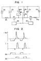
- Figure 1 is a schematic circuit diagram indicating principal parts of a power source embodying the present invention; and
- Figure 2 comprises graphical waveform diagrams illustrating gap voltage VG, gap current I and conduction timing of transistors Qh and Q, in the embodiment of Figure 1.
- In Figure 1, Vh is a second high-current source; V, is a first low-current source; Ch is a capacitor of a large capacitance; C, is a capacitor of a small capacitance; Qh and Q, are transistors for current control use; Gh and G1 are control circuit; Rh and Rl are charging resistors; R1 and R2 are voltage-dividing resistors; WIR is a wire; and WK is a workpiece.
- The wire-cut electric-discharge machining power source of the present embodiment includes a second high-current discharge circuit comprised of the second high-current source Vh, the large-capacitance capacitor Ch, the charging resistor Rh, the transistor Qh and the control circuit Gh for controlling the conduction of the transistor Qh, and a first low-current discharge circuit comprised of the first low-current source V,, the small-capacitance capacitor C,, the charging resistor R,, the transistor Q, and the control circuit G, for controling the conduction of the transistor Q,. The second high-current discharge circuit is arranged such that the side of the workpiece WK is positive and the side of the wire WIR negative, as is the case with an ordinary machining power source. Conversely, the first low-current discharge circuit is arranged such that the side of the workpiece WK is negative and the side of the wire WIR positive. In general, the lower the first power source voltage is and the higher the second power source voltage is, the more the cutting speed can be increased; accordingly, it is desirable than the first power source voltage is equal to or lower than the second power source voltage, but this relationship may also be reversed according to the thickness of the workpiece and the purpose of working. Since a discharge current of the first low-current discharge circuit is only to trigger a discharge, this discharge current is set to a very small value as compared with a discharge current of the second high-current discharge circuit. Now, a description will be given of the operation of this embodiment.
- Upon turning ON the transistor Q, by the control circuit Gl at the timing shown in waveform Ql in Figure 2, the small-capacitance capacitor C,, which is charged by the first low-current source V,, provides to the gap between the wire WIR and the workpiece WK a voltage making the former positive and the latter negative, thereby starting a discharge between them. When the discharge has thus been started, the gap voltage VG drops (rises as seen in the waveform - VG in Figure 2 in which the positive axis extends downwards), so that it is voltage-divided by the resistors R1 and R2 and then compared as by a comparator with a reference voltage to detect the start of the discharge, and the transistor Q, is turned OFF by the control circuit Gl and the transistor Qh of the second high-current discharge circuit is turned ON by the control circuit Qh (see waveform Qh in Figure 2).
- As a consequence, charges stored in the capacitor Ch, with the polarity indicated by +, - in Figure 1 are applied via the transistor Qh to the gap between the workpiece WK and the wire WIR with the former made positive and the latter negative, starting a main discharge to cut the workpiece WK. In this case, by detecting the gap voltage VG in the same manner as described above, the end of main discharge is detected and the transistor Qh is turned OFF by the control circuit Gh. Then, after the elapse of a certain period of time, the transistor Q, is turned ON again and the abovesaid discharge is repeated. In the present invention, the reason for which the discharge is produced using the charges stored in the capacitor Ch of large capacitance is that the discharge current has a large peak value of 100 to 200 A (see waveform I in Figure 2) and a small pulse width of 1 to 2 µs. By using such a capacitor Ch and turning OFF the transistor Qh at the end of discharge, it is possible to reduce a surge which is applied to the transistor Qh when it is turned OFF. The illustrated embodiment employes the capacitor Cl in the first low-current discharge circuit, but its capacitance value is very small as compared with that of the capacitor Ch and the capacitor C, can be omitted in some cases. The transistor Q, is shown to be a PNP transistor; this is intended to make the ground potentials of the control circuits Gl and Gh equal to each other. If the control circuits Gl and Gh can be grounded separately by a photo coupler of high-speed operation, and NPN transistor can also be used as the transistor Q,.
- As has been described in the foregoing, according to one aspect of the present invention, in a wire-cut electric-discharge machining power source of the type triggering a discharge by a first low-current discharge circuit and then producing a main discharge by a second high-current discharge circuit for working, the first low-current discharge circuit is connected making the wire positive and the workpiece negative. The electrolytic action on the workpiece is reduced to lessen the corrosive Influence of the electrolytic action and the application of a reverse voltage after the main discharge heightens an ion eliminating effect, so that the frequency of discharge can be increased, thus permitting high-speed machining. Since the discharge current by the first low-current source is very weak, the reverse-polarity discharge scarcely produces ill effects such as wearing of the wire and so forth.
- Thus, a wire-cut electric-discharge machining power source embodying this invention is provided with a first low-current discharge circuit and a second high-current discharge circuit. The first low-current discharge circuit is connected making a wire electrode positive and a workpiece negative, and the second high-current discharge circuit is connected making the wire electrode negative and the workpiece positive. After triggering a discharge by the first low-current discharge circuit, a main discharge for machining is produced by the second high-current discharge circuit.
Claims (7)
Applications Claiming Priority (2)
| Application Number | Priority Date | Filing Date | Title |
|---|---|---|---|
| JP12870279A JPS5656341A (en) | 1979-10-05 | 1979-10-05 | Power source for wire cut electric discharge machining |
| JP128702/79 | 1979-10-05 |
Publications (2)
| Publication Number | Publication Date |
|---|---|
| EP0027041A1 EP0027041A1 (en) | 1981-04-15 |
| EP0027041B1 true EP0027041B1 (en) | 1983-09-21 |
Family
ID=14991305
Family Applications (1)
| Application Number | Title | Priority Date | Filing Date |
|---|---|---|---|
| EP80303492A Expired EP0027041B1 (en) | 1979-10-05 | 1980-10-03 | Wire-cut electric-discharge machine, a power source for such a machine, and a method of wire-cut electric-discharge machining |
Country Status (4)
| Country | Link |
|---|---|
| US (1) | US4347425A (en) |
| EP (1) | EP0027041B1 (en) |
| JP (1) | JPS5656341A (en) |
| DE (1) | DE3064953D1 (en) |
Families Citing this family (32)
| Publication number | Priority date | Publication date | Assignee | Title |
|---|---|---|---|---|
| JPS57138530A (en) * | 1981-02-13 | 1982-08-26 | Mitsubishi Electric Corp | Electric power source apparatus for machining with electrical discharge |
| JPS57211421A (en) * | 1981-05-14 | 1982-12-25 | Fanuc Ltd | Wire cut discharge machining power source equipment |
| US4443682A (en) * | 1981-10-26 | 1984-04-17 | Colt Industries Operating Corp | Superimposed high striking voltage power supply circuit for electrical discharge machining |
| JPS6029246A (en) * | 1983-07-13 | 1985-02-14 | Fanuc Ltd | Contact sensor for electric discharge machine |
| JPS60141429A (en) * | 1983-12-26 | 1985-07-26 | Inoue Japax Res Inc | Wire-cut electric-discharge machining apparatus |
| JPS60146624A (en) * | 1984-01-09 | 1985-08-02 | Hitachi Seiko Ltd | Method of electric discharge machining and device therefor |
| JPS60201826A (en) * | 1984-03-26 | 1985-10-12 | Fanuc Ltd | Power source for wire electric discharge machining |
| WO1986000248A1 (en) * | 1984-06-29 | 1986-01-16 | Nicolas Mironoff | Electric circuit for electroerosion machining |
| JPS6150714A (en) * | 1984-08-21 | 1986-03-13 | Inoue Japax Res Inc | Power supplying device for electrical discharge machining |
| JPS61168423A (en) * | 1985-01-23 | 1986-07-30 | Hitachi Seiko Ltd | Power source device for wire electric discharge machine |
| JPH0716827B2 (en) * | 1985-02-22 | 1995-03-01 | 株式会社井上ジャパックス研究所 | Power supply for wire cut electrical discharge machining |
| JPS61249213A (en) * | 1985-04-25 | 1986-11-06 | Hitachi Seiko Ltd | Electric power source apparatus for wire electric discharge machine |
| US4751363A (en) * | 1986-02-28 | 1988-06-14 | Ho Kuang Ta | Automatic turn-on fine finish circuit for electrical discharge machining |
| US4786778A (en) * | 1986-08-29 | 1988-11-22 | Ho Kuang Ta | Electrical discharge machining fine finish circuit with symmetrical waveform in both polarities |
| JPS63102825A (en) * | 1986-10-20 | 1988-05-07 | Fanuc Ltd | Power source for electric discharge machining |
| US5126525A (en) * | 1988-11-01 | 1992-06-30 | Sodick Co., Ltd. | Power supply system for electric discharge machines |
| JPH03104517A (en) * | 1989-09-18 | 1991-05-01 | Mitsubishi Electric Corp | Power source device for electric discharge processing |
| JP2536223B2 (en) * | 1990-03-28 | 1996-09-18 | 三菱電機株式会社 | Contact detection device |
| JP2939310B2 (en) * | 1990-08-14 | 1999-08-25 | 株式会社ソディック | Electric discharge machine |
| JP2692510B2 (en) * | 1991-12-02 | 1997-12-17 | 三菱電機株式会社 | Electric discharge machine |
| JP2988086B2 (en) * | 1991-12-24 | 1999-12-06 | 三菱電機株式会社 | Electric discharge machine |
| JP3343267B2 (en) * | 1992-08-25 | 2002-11-11 | 株式会社ソディック | Electric discharge machining method and power supply device for electric discharge machining |
| JP3057953B2 (en) * | 1993-02-25 | 2000-07-04 | 株式会社ソディック | Wire cut electric discharge machine |
| DE4432916C1 (en) * | 1994-09-15 | 1996-04-04 | Agie Ag Ind Elektronik | Process and pulse generator for electroerosive machining of workpieces |
| TWI226270B (en) * | 2002-12-26 | 2005-01-11 | Ind Tech Res Inst | Method and apparatus of asynchronous wire-cutting electric discharge machine |
| CN102076454B (en) * | 2008-07-24 | 2012-10-10 | 三菱电机株式会社 | Electrical discharge machining device, electrical discharge machining method, and semiconductor substrate manufacturing method |
| JP5155418B2 (en) * | 2011-03-07 | 2013-03-06 | ファナック株式会社 | EDM machine |
| JP5887378B2 (en) * | 2014-04-30 | 2016-03-16 | ファナック株式会社 | Machining power supply device for electrical discharge machine |
| JP6514163B2 (en) * | 2016-09-01 | 2019-05-15 | ファナック株式会社 | Wire electric discharge machine |
| CN109570658B (en) * | 2018-11-30 | 2020-02-14 | 北京信息科技大学 | Capacitance-induced micro electric spark machining pulse power supply |
| JP6740390B2 (en) * | 2019-01-08 | 2020-08-12 | ファナック株式会社 | Wire electric discharge machine |
| WO2023223479A1 (en) * | 2022-05-18 | 2023-11-23 | 三菱電機株式会社 | Electric discharge machining power supply device, electric discharge machining device, and electric discharge machining method |
Family Cites Families (10)
| Publication number | Priority date | Publication date | Assignee | Title |
|---|---|---|---|---|
| US2951930A (en) * | 1958-02-26 | 1960-09-06 | Elox Corp Michigan | Pulsed arc machining |
| US3509305A (en) * | 1966-07-27 | 1970-04-28 | Amsted Ind Inc | Random gap pulsing system for edm |
| US3504154A (en) * | 1966-08-03 | 1970-03-31 | Victor H Marcolini | Edm power supply with separate sources of gap ionizing potential and material eroding energy |
| US3549851A (en) * | 1966-12-19 | 1970-12-22 | Siltronics Inc | Power supply circuitry for increasing capacitance-charging rate and discharge duration in electric discharge machining apparatus |
| US3654116A (en) * | 1968-08-07 | 1972-04-04 | Inoue K | Adaptive ion-control system for electrochemical machining |
| CH516971A (en) * | 1969-11-24 | 1971-12-31 | Amsted Ind Inc | Device for spark erosion of a workpiece |
| NL7001538A (en) * | 1970-02-04 | 1971-08-06 | ||
| NL7116823A (en) * | 1971-12-08 | 1973-06-13 | ||
| US4211908A (en) * | 1974-02-19 | 1980-07-08 | Mitsubishi Denki Kabushiki Kaisha | Apparatus for high frequency discharge shaping of a workpiece by means of a rectangular bipolar pulsating voltage |
| JPS50123053A (en) * | 1974-03-12 | 1975-09-27 |
-
1979
- 1979-10-05 JP JP12870279A patent/JPS5656341A/en active Granted
-
1980
- 1980-09-29 US US06/191,448 patent/US4347425A/en not_active Expired - Lifetime
- 1980-10-03 DE DE8080303492T patent/DE3064953D1/en not_active Expired
- 1980-10-03 EP EP80303492A patent/EP0027041B1/en not_active Expired
Also Published As
| Publication number | Publication date |
|---|---|
| DE3064953D1 (en) | 1983-10-27 |
| JPS6317569B2 (en) | 1988-04-14 |
| EP0027041A1 (en) | 1981-04-15 |
| US4347425A (en) | 1982-08-31 |
| JPS5656341A (en) | 1981-05-18 |
Similar Documents
| Publication | Publication Date | Title |
|---|---|---|
| EP0027041B1 (en) | Wire-cut electric-discharge machine, a power source for such a machine, and a method of wire-cut electric-discharge machining | |
| US3999028A (en) | Method and apparatus for electrical discharge machining | |
| EP0166786B1 (en) | Positioning apparatus for electric discharge machine | |
| EP0034477B1 (en) | A power source circuit for an electric discharge machine | |
| EP0032023B1 (en) | A power source for an electric discharge machine | |
| JP3343267B2 (en) | Electric discharge machining method and power supply device for electric discharge machining | |
| US4672161A (en) | EDM method and apparatus with trapezoidized short-duration pulses | |
| GB1571776A (en) | Electric spark erosion process and machine | |
| US3549851A (en) | Power supply circuitry for increasing capacitance-charging rate and discharge duration in electric discharge machining apparatus | |
| GB1505065A (en) | Methods and apparatus for electrically machining a workpiece | |
| EP0081587B1 (en) | Wire cut electric discharge machining power source | |
| EP0038662B1 (en) | A power source arrangement for an electric discharge machine | |
| JPH0564032B2 (en) | ||
| KR830002267B1 (en) | Wire-Cut EDM Power | |
| GB2081633A (en) | Electrical discharge machining method and apparatus | |
| EP1208934A2 (en) | Electric discharge machining apparatus | |
| RU72894U1 (en) | TECHNOLOGICAL CURRENT PULSE GENERATOR | |
| EP0185101B1 (en) | Power source for discharge machining | |
| JPS6116572B2 (en) | ||
| JPH059209B2 (en) | ||
| JP2801280B2 (en) | Wire cut EDM power supply | |
| US5486765A (en) | Insulating condition detecting apparatus for a wire-cut electrical discharge machine | |
| JPH01234114A (en) | Power supply device for electric discharge machining | |
| US3231782A (en) | Electrical stock removal method and apparatus | |
| SU1202767A1 (en) | Apparatus for controlling the feed of tool electrode in electro-erosion machines |
Legal Events
| Date | Code | Title | Description |
|---|---|---|---|
| PUAI | Public reference made under article 153(3) epc to a published international application that has entered the european phase |
Free format text: ORIGINAL CODE: 0009012 |
|
| AK | Designated contracting states |
Designated state(s): CH DE FR GB |
|
| RBV | Designated contracting states (corrected) |
Designated state(s): CH DE FR GB LI |
|
| 17P | Request for examination filed |
Effective date: 19810518 |
|
| RAP1 | Party data changed (applicant data changed or rights of an application transferred) |
Owner name: FANUC LIMITED |
|
| GRAA | (expected) grant |
Free format text: ORIGINAL CODE: 0009210 |
|
| AK | Designated contracting states |
Designated state(s): CH DE FR GB LI |
|
| REF | Corresponds to: |
Ref document number: 3064953 Country of ref document: DE Date of ref document: 19831027 |
|
| ET | Fr: translation filed | ||
| PLBE | No opposition filed within time limit |
Free format text: ORIGINAL CODE: 0009261 |
|
| STAA | Information on the status of an ep patent application or granted ep patent |
Free format text: STATUS: NO OPPOSITION FILED WITHIN TIME LIMIT |
|
| 26N | No opposition filed | ||
| PGFP | Annual fee paid to national office [announced via postgrant information from national office to epo] |
Ref country code: FR Payment date: 19910912 Year of fee payment: 12 |
|
| PGFP | Annual fee paid to national office [announced via postgrant information from national office to epo] |
Ref country code: GB Payment date: 19910924 Year of fee payment: 12 |
|
| PG25 | Lapsed in a contracting state [announced via postgrant information from national office to epo] |
Ref country code: GB Effective date: 19921003 |
|
| GBPC | Gb: european patent ceased through non-payment of renewal fee |
Effective date: 19921003 |
|
| PG25 | Lapsed in a contracting state [announced via postgrant information from national office to epo] |
Ref country code: FR Effective date: 19930630 |
|
| REG | Reference to a national code |
Ref country code: FR Ref legal event code: ST |
|
| PGFP | Annual fee paid to national office [announced via postgrant information from national office to epo] |
Ref country code: DE Payment date: 19931011 Year of fee payment: 14 |
|
| PGFP | Annual fee paid to national office [announced via postgrant information from national office to epo] |
Ref country code: CH Payment date: 19931013 Year of fee payment: 14 |
|
| PG25 | Lapsed in a contracting state [announced via postgrant information from national office to epo] |
Ref country code: LI Effective date: 19941031 Ref country code: CH Effective date: 19941031 |
|
| REG | Reference to a national code |
Ref country code: CH Ref legal event code: PL |
|
| PG25 | Lapsed in a contracting state [announced via postgrant information from national office to epo] |
Ref country code: DE Effective date: 19950701 |