EP0025871B1 - Verfahren zum Herstellen eines Reaktionsgemisches aus fliessfähigen, Schaum- oder Massivstoff bildenden Komponenten - Google Patents
Verfahren zum Herstellen eines Reaktionsgemisches aus fliessfähigen, Schaum- oder Massivstoff bildenden Komponenten Download PDFInfo
- Publication number
- EP0025871B1 EP0025871B1 EP80104893A EP80104893A EP0025871B1 EP 0025871 B1 EP0025871 B1 EP 0025871B1 EP 80104893 A EP80104893 A EP 80104893A EP 80104893 A EP80104893 A EP 80104893A EP 0025871 B1 EP0025871 B1 EP 0025871B1
- Authority
- EP
- European Patent Office
- Prior art keywords
- pressure
- reaction mixture
- injection pressure
- measured
- circulation
- Prior art date
- Legal status (The legal status is an assumption and is not a legal conclusion. Google has not performed a legal analysis and makes no representation as to the accuracy of the status listed.)
- Expired
Links
Images

Classifications
-
- B—PERFORMING OPERATIONS; TRANSPORTING
- B29—WORKING OF PLASTICS; WORKING OF SUBSTANCES IN A PLASTIC STATE IN GENERAL
- B29B—PREPARATION OR PRETREATMENT OF THE MATERIAL TO BE SHAPED; MAKING GRANULES OR PREFORMS; RECOVERY OF PLASTICS OR OTHER CONSTITUENTS OF WASTE MATERIAL CONTAINING PLASTICS
- B29B7/00—Mixing; Kneading
- B29B7/74—Mixing; Kneading using other mixers or combinations of mixers, e.g. of dissimilar mixers ; Plant
- B29B7/76—Mixers with stream-impingement mixing head
- B29B7/7663—Mixers with stream-impingement mixing head the mixing head having an outlet tube with a reciprocating plunger, e.g. with the jets impinging in the tube
-
- B—PERFORMING OPERATIONS; TRANSPORTING
- B29—WORKING OF PLASTICS; WORKING OF SUBSTANCES IN A PLASTIC STATE IN GENERAL
- B29B—PREPARATION OR PRETREATMENT OF THE MATERIAL TO BE SHAPED; MAKING GRANULES OR PREFORMS; RECOVERY OF PLASTICS OR OTHER CONSTITUENTS OF WASTE MATERIAL CONTAINING PLASTICS
- B29B7/00—Mixing; Kneading
- B29B7/30—Mixing; Kneading continuous, with mechanical mixing or kneading devices
- B29B7/58—Component parts, details or accessories; Auxiliary operations
- B29B7/72—Measuring, controlling or regulating
- B29B7/726—Measuring properties of mixture, e.g. temperature or density
-
- B—PERFORMING OPERATIONS; TRANSPORTING
- B29—WORKING OF PLASTICS; WORKING OF SUBSTANCES IN A PLASTIC STATE IN GENERAL
- B29B—PREPARATION OR PRETREATMENT OF THE MATERIAL TO BE SHAPED; MAKING GRANULES OR PREFORMS; RECOVERY OF PLASTICS OR OTHER CONSTITUENTS OF WASTE MATERIAL CONTAINING PLASTICS
- B29B7/00—Mixing; Kneading
- B29B7/30—Mixing; Kneading continuous, with mechanical mixing or kneading devices
- B29B7/58—Component parts, details or accessories; Auxiliary operations
- B29B7/72—Measuring, controlling or regulating
- B29B7/728—Measuring data of the driving system, e.g. torque, speed, power, vibration
-
- B—PERFORMING OPERATIONS; TRANSPORTING
- B29—WORKING OF PLASTICS; WORKING OF SUBSTANCES IN A PLASTIC STATE IN GENERAL
- B29B—PREPARATION OR PRETREATMENT OF THE MATERIAL TO BE SHAPED; MAKING GRANULES OR PREFORMS; RECOVERY OF PLASTICS OR OTHER CONSTITUENTS OF WASTE MATERIAL CONTAINING PLASTICS
- B29B7/00—Mixing; Kneading
- B29B7/74—Mixing; Kneading using other mixers or combinations of mixers, e.g. of dissimilar mixers ; Plant
- B29B7/76—Mixers with stream-impingement mixing head
- B29B7/7615—Mixers with stream-impingement mixing head characterised by arrangements for controlling, measuring or regulating, e.g. for feeding or proportioning the components
-
- B—PERFORMING OPERATIONS; TRANSPORTING
- B29—WORKING OF PLASTICS; WORKING OF SUBSTANCES IN A PLASTIC STATE IN GENERAL
- B29B—PREPARATION OR PRETREATMENT OF THE MATERIAL TO BE SHAPED; MAKING GRANULES OR PREFORMS; RECOVERY OF PLASTICS OR OTHER CONSTITUENTS OF WASTE MATERIAL CONTAINING PLASTICS
- B29B7/00—Mixing; Kneading
- B29B7/74—Mixing; Kneading using other mixers or combinations of mixers, e.g. of dissimilar mixers ; Plant
- B29B7/76—Mixers with stream-impingement mixing head
- B29B7/7631—Parts; Accessories
- B29B7/7636—Construction of the feed orifices, bores, ports
- B29B7/7642—Adjustable feed orifices, e.g. for controlling the rate of feeding
-
- G—PHYSICS
- G05—CONTROLLING; REGULATING
- G05D—SYSTEMS FOR CONTROLLING OR REGULATING NON-ELECTRIC VARIABLES
- G05D7/00—Control of flow
- G05D7/06—Control of flow characterised by the use of electric means
- G05D7/0617—Control of flow characterised by the use of electric means specially adapted for fluid materials
- G05D7/0629—Control of flow characterised by the use of electric means specially adapted for fluid materials characterised by the type of regulator means
- G05D7/0676—Control of flow characterised by the use of electric means specially adapted for fluid materials characterised by the type of regulator means by action on flow sources
-
- B—PERFORMING OPERATIONS; TRANSPORTING
- B29—WORKING OF PLASTICS; WORKING OF SUBSTANCES IN A PLASTIC STATE IN GENERAL
- B29B—PREPARATION OR PRETREATMENT OF THE MATERIAL TO BE SHAPED; MAKING GRANULES OR PREFORMS; RECOVERY OF PLASTICS OR OTHER CONSTITUENTS OF WASTE MATERIAL CONTAINING PLASTICS
- B29B7/00—Mixing; Kneading
- B29B7/74—Mixing; Kneading using other mixers or combinations of mixers, e.g. of dissimilar mixers ; Plant
- B29B7/76—Mixers with stream-impingement mixing head
- B29B7/7663—Mixers with stream-impingement mixing head the mixing head having an outlet tube with a reciprocating plunger, e.g. with the jets impinging in the tube
- B29B7/7684—Parts; Accessories
- B29B7/7689—Plunger constructions
- B29B7/7694—Plunger constructions comprising recirculation channels; ducts formed in the plunger
-
- Y—GENERAL TAGGING OF NEW TECHNOLOGICAL DEVELOPMENTS; GENERAL TAGGING OF CROSS-SECTIONAL TECHNOLOGIES SPANNING OVER SEVERAL SECTIONS OF THE IPC; TECHNICAL SUBJECTS COVERED BY FORMER USPC CROSS-REFERENCE ART COLLECTIONS [XRACs] AND DIGESTS
- Y10—TECHNICAL SUBJECTS COVERED BY FORMER USPC
- Y10S—TECHNICAL SUBJECTS COVERED BY FORMER USPC CROSS-REFERENCE ART COLLECTIONS [XRACs] AND DIGESTS
- Y10S521/00—Synthetic resins or natural rubbers -- part of the class 520 series
- Y10S521/917—Specialized mixing apparatus utilized in cell forming process
Definitions
- Cavities are filled in by means of the reaction mixture generated and molded parts are produced in particular in molds.
- the throughput of the components which depend on various factors such as viscosity, temperature, pressure, must be continuously monitored. Since these factors are caused by fluctuations in the nature of the components and by tolerances in the way the device works, preventive measures cannot keep them completely constant. It is therefore necessary to keep the throughput constant when these factors change.
- the metering pumps are tested by allowing the quantity delivered per unit of time to run out at a certain pressure at various pump control path settings and then weighing them.
- the mixing device is adjusted in the correct prescribed stoichiometric ratio. This happens before the start of production. Compliance with the determined values cannot be checked during production. The entire time-consuming, complex test procedure must therefore be repeated at certain intervals so that there is sufficient production security.
- This test method also has a large uncertainty factor in it, since the weight measurement is carried out exclusively under atmospheric pressure and, if the component contains blowing agents, it may escape due to its low boiling point.
- the task is to create a method for the safe, automatic regulation and monitoring of the throughput quantities during the injection and the circulation at predetermined pressures.
- This iterative control procedure allows the throughput quantity to be monitored automatically.
- the particular advantage is that the monitoring is carried out continuously and no interruption of the actual workflow is required.
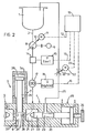
- a supply line 2 leads from a storage container 1 to a mixing head 3. This consists of nozzles 4, 5, a mixing chamber 6 (FIG. 2) and a cleaning device 7.
- a Dosing pump 8 is provided, which is associated with a drive 9 operating at constant speed.
- the metering pump 8 has an adjusting device 10 symbolized by an arrow, to which an actuator 11 designed as a servo motor is assigned. This is connected to a control computer 13 via a pulse line 12.
- a pressure measuring device 14 arranged in the feed line 2 is coupled to a pressure display device 15 and connected to the control computer 13 via a pulse line 16.
- a volume flow meter 17 is also switched on in the feed line 2, which is coupled to a quantity display device 18 and is connected to the control computer 13 via a pulse line 19.
- the feed line 2 opens into the nozzle housing 20.
- a nozzle needle 22 is guided in a bore 21, which has a circulation channel 23 and closes the nozzle opening 24 pointing into the mixing chamber 6 in FIG. 1, but releases it in FIG. 2.
- a return line 25 branches off from this housing 20 and opens into the storage container 1.
- the circulation channel 23 establishes the connection to the return line 25 via the bore 21, while in FIG. 2 the nozzle needle 22 interrupts that circulation, so that the component can enter the mixing chamber via the nozzle opening 24.
- the stroke of the nozzle needle 22 is adjustable by means of a stroke adjusting device 26 designed as an adjusting screw, whereby the free flow cross-section between the tip 27 of the nozzle needle 22 and the nozzle seat 28 can be adjusted.
- the nozzle needle 22 can be switched via a hydraulic motor 29.
- a throttle element 30 is arranged in the return line 25 and has an adjusting device 31, which is symbolized by an arrow. The latter is coupled to a servo motor serving as actuator 32. This is connected to the control computer 13 via a pulse line 33.
- the cleaning device 7 consists of a housing 34 in which a cleaning piston 35 is guided. It can be actuated by a hydraulic motor 36. In Fig. 1, the cleaning piston 35 is in the ejection position and has displaced the mixture from the mixing chamber, while in Fig. 2 it assumes the mixing position, so that the mixing chamber 6 is formed in its guide bore 37.
- the delivery rate of the dosing pump depends on the back pressure.
- the throughput quantity Q is given as a function of the control path Rw of the adjusting device of the metering pump.
- the pressure readable on the display device 15 in bar and the throughput quantity readable on the display device 18 in kg / min are the reference variables.
- the actuator 11 for the control path adjustment device 10 of the metering pump 8 and the actuator 32 for the adjustment device 31 of the throttle path of the throttle member 30 and the adjustment device designed as a stop screw 26 for the stroke of the injection nozzle needle 22 are the manipulated variables.
- the actual control process now begins by initially feeding the setpoints into the control computer 13, which processes the command and manipulated variables.
- the throughput for a component should, for. B. 10 kg / min with a maximum deviation of ⁇ 0.1 kg / min.
- the injection pressure should be between 120 and 180 bar. This is the pressure range from which experience has shown that the mixture of injections is sufficiently intensive for the mixture to be processed.
- the mean value of the injection pressure range which is 150 bar, is advantageously selected as the preset pressure for the circuit. The actual pressure arising during the regulation should be maintained or adjusted with an accuracy of ⁇ 2 bar.
- the adjusting motor 11 for the adjusting device 10 of the metering pump 8 travels on a control path of 2.3 mm, which corresponds to a throughput of 9.4 kg / min.
- the adjusting motor 32 for the adjusting device 31 of the throttle element 30 travels in a distance of 2.07 mm. Under these conditions, the working pressure on the pressure display device 15 is 138 bar. Now the regulation begins according to the following scheme:
- the control computer 13 After switching to injection, which initiates the mixing process, there is first a pressure comparison. If the effective injection pressure is not in the predetermined pressure range of 120 to 180 bar, the adjusting device 26 of the nozzle needle 22 must be readjusted by hand. If the injection pressure is within the specified pressure range, the pressure that is actually set is registered in the control computer 13 and, after switching back to the circuit, is considered a new setpoint or a new reference variable. In the example above, this value is 135 bar. Now follow the further control steps in the cycle until the values are within the new tolerance range. Then, in turn, the system switches to injection and the injection pressure that is set is registered in the control computer 13.
- the circuit is readjusted, whereby the value of the injection pressure last registered is now the new setpoint for the circuit pressure. In the example it is 130 bar. Circulation pressure and injection pressure approach iteratively. Further adjustment and control steps can be carried out. In the prescribed example, after a new switch to injection, equality in the pressure level is determined for a given volume throughput with permissible deviations. After only three control or adjustment processes, the facility has approached the desired value level interactively. With each further injection, these values are compared, saved and readjusted.
- the injection pressure is measured and stored. If the injection pressure is in the specified injection pressure range, the circulatory adjustment is again carried out using the measured and stored value of the injection pressure. If the measured value of the injection pressure is outside the specified range, the control must be interrupted and the nozzle readjusted by hand. Only then does the cycle adjustment follow again.
Landscapes
- Engineering & Computer Science (AREA)
- Mechanical Engineering (AREA)
- Physics & Mathematics (AREA)
- General Physics & Mathematics (AREA)
- Automation & Control Theory (AREA)
- Injection Moulding Of Plastics Or The Like (AREA)
- Processing And Handling Of Plastics And Other Materials For Molding In General (AREA)
- Molding Of Porous Articles (AREA)
- Casting Or Compression Moulding Of Plastics Or The Like (AREA)
- Manufacture Of Porous Articles, And Recovery And Treatment Of Waste Products (AREA)
Priority Applications (1)
| Application Number | Priority Date | Filing Date | Title |
|---|---|---|---|
| AT80104893T ATE2883T1 (de) | 1979-09-07 | 1980-08-16 | Verfahren zum herstellen eines reaktionsgemisches aus fliessfaehigen, schaumoder massivstoff bildenden komponenten. |
Applications Claiming Priority (2)
| Application Number | Priority Date | Filing Date | Title |
|---|---|---|---|
| DE2936223 | 1979-09-07 | ||
| DE19792936223 DE2936223A1 (de) | 1979-09-07 | 1979-09-07 | Verfahren und einrichtung zum herstellen eines reaktionsgemisches aus fliessfaehigen, schaum- oder massivstoff bildenden komponenten |
Publications (2)
| Publication Number | Publication Date |
|---|---|
| EP0025871A1 EP0025871A1 (de) | 1981-04-01 |
| EP0025871B1 true EP0025871B1 (de) | 1983-03-30 |
Family
ID=6080318
Family Applications (1)
| Application Number | Title | Priority Date | Filing Date |
|---|---|---|---|
| EP80104893A Expired EP0025871B1 (de) | 1979-09-07 | 1980-08-16 | Verfahren zum Herstellen eines Reaktionsgemisches aus fliessfähigen, Schaum- oder Massivstoff bildenden Komponenten |
Country Status (5)
| Country | Link |
|---|---|
| US (2) | US4399104A (enExample) |
| EP (1) | EP0025871B1 (enExample) |
| JP (1) | JPS5644640A (enExample) |
| AT (1) | ATE2883T1 (enExample) |
| DE (2) | DE2936223A1 (enExample) |
Families Citing this family (47)
| Publication number | Priority date | Publication date | Assignee | Title |
|---|---|---|---|---|
| DE3021095C2 (de) * | 1980-06-04 | 1983-12-22 | Maschinenfabrik Hennecke Gmbh, 5090 Leverkusen | Verfahren und Vorrichtung zum Herstellen eines Massiv- oder Schaumstoff bildenden Reaktionsgemisches aus mindestens zwei fließfähigen Reaktionskomponenten |
| IT1135030B (it) * | 1981-01-14 | 1986-08-20 | Afros Spa | Iniettore telecomandato per teste miscelatrici di componenti chimici da alimentare ad uno stampo |
| IT1135043B (it) * | 1981-01-15 | 1986-08-20 | Afros Spa | Testa di miscelazione per sostanze chimiche reattive,con iniettori telecomandati |
| DE3111957A1 (de) * | 1981-03-26 | 1982-10-07 | Maschinenfabrik Hennecke Gmbh, 5090 Leverkusen | Einrichtung zum herstellen eines schaumstoff oder massivstoff bildenden fliessfaehigen reaktionsgemisches aus mindestens zwei fliessfaehigen komponenten |
| DE3120974C2 (de) * | 1981-05-26 | 1987-03-26 | Fa. Hans Wilmsen, 4300 Essen | Vorrichtung zum Ausschäumen von Hohlräumen mit Aminoplastschaum |
| DE3201903A1 (de) * | 1982-01-22 | 1983-08-04 | Elastogran Maschinenbau GmbH, 2844 Lemförde | Vorrichtung zum erzeugen eines vorzugsweise chemisch reaktionsfaehigen gemisches aus mindestens zwei kunststoffkomponeneten |
| DE3239551A1 (de) * | 1982-10-26 | 1984-04-26 | Krauss-Maffei AG, 8000 München | Vorrichtung zum zuleiten eines insbesondere chemisch reaktionsfaehigen kunststoffgemisches zu einer form (mischkopf) |
| US4526907A (en) * | 1983-05-07 | 1985-07-02 | Basf Aktiengesellschaft | Process and device for the preparation of a reaction mixture of at least two components for the production of foams |
| JPH0320092Y2 (enExample) * | 1985-03-22 | 1991-04-30 | ||
| US4590218A (en) * | 1985-06-19 | 1986-05-20 | The O'brien Corporation | Method and apparatus for forming a chemical composition from cross-linking components and product of the method |
| DE3522153A1 (de) * | 1985-06-21 | 1987-01-02 | Bayer Ag | Kolbendosiergeraet zur herstellung eines kunststoff, insbesondere schaumstoff bildenden, fliessfaehigen reaktionsgemisches aus mindestens zwei fliessfaehigen reaktionskomponenten |
| DE3616463A1 (de) * | 1986-05-15 | 1987-11-19 | Battenfeld Maschfab | Vorrichtung zum dosieren von reaktionsgemischen |
| DE3637896A1 (de) * | 1986-11-06 | 1988-06-16 | Krauss Maffei Ag | Verfahren zum mischen und spritzen eines zweikomponenten-kunstharzes |
| US4966466A (en) * | 1987-11-10 | 1990-10-30 | Krauss-Maffei A.G. | Impingement mixing device with pressure controlled nozzle adjustment |
| US4854713A (en) * | 1987-11-10 | 1989-08-08 | Krauss-Maffei A.G. | Impingement mixing device with pressure controlled nozzle adjustment |
| US4944599A (en) * | 1987-11-10 | 1990-07-31 | Krauss-Maffei A.G. | Impingement mixing device with pressure controlled nozzle adjustment |
| DE3828061C1 (enExample) * | 1988-08-18 | 1989-11-16 | Maschinenfabrik Hennecke Gmbh, 5090 Leverkusen, De | |
| US5154088A (en) * | 1990-07-24 | 1992-10-13 | The Dow Chemical Company | Apparatuses and methods for incorporating blowing agents into liquids for the production of polymer foams and for measuring the volumetric expansion potential of mixtures thereof |
| US5119668A (en) * | 1990-07-24 | 1992-06-09 | The Dow Chemical Company | Apparatuses and methods for incorporating blowing agents into liquids for the production of polymer foams and for measuring the volumetric expansion potential of mixtures thereof |
| JPH04151211A (ja) * | 1990-10-15 | 1992-05-25 | Iketsukusu Kogyo:Kk | 注型成形機の注入口装置 |
| CA2057948A1 (en) * | 1991-01-11 | 1992-07-12 | James W. Schmitkons | Method and apparatus for metering flow of a two-component dispensing system |
| US5271521A (en) * | 1991-01-11 | 1993-12-21 | Nordson Corporation | Method and apparatus for compensating for changes in viscosity in a two-component dispensing system |
| DE4103532C1 (enExample) * | 1991-02-06 | 1992-09-03 | Maschinenfabrik Hennecke Gmbh, 5090 Leverkusen, De | |
| DE4119966C2 (de) * | 1991-06-18 | 1996-02-08 | Spuehl Ag | Meßeinrichtung zur Erfassung der Gasbeladung einer Kunststoffkomponente |
| DE4128999A1 (de) * | 1991-08-31 | 1993-03-04 | Adrian Verstallen | Verfahren und vorrichtung zum vermischen schwer mischbarer fluide zur bildung einer dispersion insbesondere emulsion |
| US5270013A (en) * | 1992-05-06 | 1993-12-14 | Decker Herman W | Reactive fluid mixing head |
| US5453250A (en) * | 1992-07-16 | 1995-09-26 | Bayer Aktiengesellschaft | Apparatus for the preparation of a flowable reaction mixture |
| US5482369A (en) * | 1993-02-08 | 1996-01-09 | Verstallen; Adrian | Process for homogenizing essentially immiscible liquids for forming an emulsion |
| WO1994025238A1 (en) * | 1993-05-05 | 1994-11-10 | E.I. Du Pont De Nemours And Company | Precision liquid addition device |
| US5615949A (en) * | 1995-08-08 | 1997-04-01 | Woodbridge Foam Corporation | High pressure mixing system and process for producing foamed isocyanate-based polymers containing filler material |
| JP3725621B2 (ja) | 1996-06-21 | 2005-12-14 | 同和鉱業株式会社 | 記録用または音響もしくは画像送信用高純度銀線 |
| US6627149B1 (en) | 1996-06-21 | 2003-09-30 | Dowa Mining Co., Ltd. | High-purity silver wires for use in recording, acoustic or image transmission applications |
| KR20020063933A (ko) * | 2000-01-20 | 2002-08-05 | 크라우스-마파이 쿤스트쉬토프테히닉 게엠베하 | 반응 주조기의 믹싱 헤드용 분사 노즐 |
| DE10216143A1 (de) * | 2002-04-12 | 2003-10-23 | Bayer Ag | Vorrichtung zur Dosierung von Gasen |
| DE10300101A1 (de) * | 2003-01-07 | 2004-07-22 | Hennecke Gmbh | Verfahren zur Herstellung von Polyurethan-Formteilen |
| DE10304593B4 (de) * | 2003-02-05 | 2005-04-21 | Klöckner Desma Schuhmaschinen GmbH | Vorrichtung in Polyurethan verarbeitenden Spritzgießmaschinen zur Druckeinstellung |
| DE10306523A1 (de) * | 2003-02-14 | 2004-08-26 | Hennecke Gmbh | Verfahren zur Herstellung von Polyurethan-Formteilen |
| PT103101B (pt) * | 2004-04-05 | 2012-07-30 | Faculdade De Engenharia Da Universidade Do Porto | Processo de produção de peças plásticas por reacção, injecção e moldagem, e respectiva máquina |
| US20080085219A1 (en) * | 2006-10-05 | 2008-04-10 | Beebe David J | Microfluidic platform and method |
| DE102007016785A1 (de) * | 2007-04-05 | 2008-10-09 | Hennecke Gmbh | Verfahren zur Herstellung von Formteilen mit einer Schicht aus Polyurethan |
| JP5643108B2 (ja) | 2008-11-27 | 2014-12-17 | 株式会社イノアックコーポレーション | ミキシングヘッド装置及びこれを用いた成形方法 |
| WO2011066095A1 (en) * | 2009-11-24 | 2011-06-03 | Dow Global Technologies Inc. | Fluid mixing and dispensing apparatus and process |
| CN102009445A (zh) * | 2010-09-21 | 2011-04-13 | 上海大学 | 全自动真空注型控制系统和方法 |
| DE102010043329A1 (de) * | 2010-11-03 | 2012-05-03 | Bayer Materialscience Aktiengesellschaft | Verfahren zur Herstellung von geschäumten Formkörpern |
| JP7102811B2 (ja) * | 2018-03-16 | 2022-07-20 | マツダ株式会社 | 流動材料供給装置 |
| JP7021575B2 (ja) * | 2018-03-16 | 2022-02-17 | マツダ株式会社 | 多液混合装置 |
| DE102024105222B3 (de) * | 2024-02-23 | 2025-07-24 | Hennecke Gmbh | Verfahren und Vorrichtung zur Produktion von Polyurethan-Bauteilen |
Citations (1)
| Publication number | Priority date | Publication date | Assignee | Title |
|---|---|---|---|---|
| DE2724132A1 (de) * | 1977-05-27 | 1978-11-30 | Bayer Ag | Verfahren und vorrichtung zum herstellen eines schaumstoffbildenden reaktionsgemisches |
Family Cites Families (14)
| Publication number | Priority date | Publication date | Assignee | Title |
|---|---|---|---|---|
| US3539784A (en) * | 1967-07-31 | 1970-11-10 | Texaco Inc | Process instrumentation and control through measurements of time-separated process variables |
| US3857550A (en) * | 1972-04-20 | 1974-12-31 | Bayer Ag | Machine for producing foams, homogeneous or structural materials from at least two liquid reaction components |
| US3843099A (en) * | 1973-02-26 | 1974-10-22 | Usm Corp | Instantaneous rationing means |
| DE2364922A1 (de) * | 1973-12-28 | 1975-07-17 | Mirabed Ag | Dosiereinrichtung zur herstellung von schaumstoff aus kunststoff |
| DE2413337C3 (de) * | 1974-03-20 | 1983-03-31 | Bayer Ag, 5090 Leverkusen | Mit einem Formwerkzeug kombinierte Mischeinrichtung |
| US4198374A (en) * | 1975-01-03 | 1980-04-15 | Societe Anonyme De Telecommunications | Volatile liquid supply equipment and processes for introducing volatile cross-linking agents into polyolefin compounds and for the extrusion of cross-linkable polyolefin compounds |
| DE2527378B2 (de) * | 1975-06-19 | 1977-07-14 | Bayer Ag, 5090 Leverkusen | Verfahren und vorrichtung zur dosierung von mehrkomponenten-fluessigsystemen |
| DE2529735C3 (de) * | 1975-07-01 | 1978-06-08 | Max-Planck-Gesellschaft Zur Foerderung Der Wissenschaften E.V., 3400 Goettingen | Korpuskularstrahlmikroskop, insbe- · sondere Elektronenmikroskop, mit Verstelleinrichtungen zur Änderung der Lage des abzubildenden Objekts und Verfahren zum Betrieb |
| US4265858A (en) * | 1976-03-31 | 1981-05-05 | Nordson Corporation | Metering and mixing apparatus for multiple component |
| DE2758096C2 (de) * | 1977-12-24 | 1984-05-24 | Behr, Hans, 7000 Stuttgart | Verfahren und Vorrichtung zum automatischen dynamischen Dosieren mindestens einer flüssigen Komponente einer Mischflüssigkeit |
| DE2805946A1 (de) * | 1978-02-13 | 1979-08-16 | Bayer Ag | Vorrichtung zum dosieren mindestens zweier fliessfaehiger reaktionskomponenten in eine mischkammer |
| US4239732A (en) * | 1979-04-13 | 1980-12-16 | The Martin Sweets Company, Inc. | High velocity mixing system |
| US4376172A (en) * | 1982-02-01 | 1983-03-08 | Cincinnati Milacron Inc. | Closed loop control of compressible fluid addition to a mixture of such fluid and a liquid |
| US4396729A (en) * | 1982-04-23 | 1983-08-02 | Texaco Inc. | Reaction injection molded elastomer containing an internal mold release made by a two-stream system |
-
1979
- 1979-09-07 DE DE19792936223 patent/DE2936223A1/de not_active Withdrawn
-
1980
- 1980-08-16 EP EP80104893A patent/EP0025871B1/de not_active Expired
- 1980-08-16 DE DE8080104893T patent/DE3062536D1/de not_active Expired
- 1980-08-16 AT AT80104893T patent/ATE2883T1/de active
- 1980-09-02 US US06/183,487 patent/US4399104A/en not_active Expired - Lifetime
- 1980-09-05 JP JP12247080A patent/JPS5644640A/ja active Granted
-
1982
- 1982-12-16 US US06/450,414 patent/US4448902A/en not_active Expired - Lifetime
Patent Citations (1)
| Publication number | Priority date | Publication date | Assignee | Title |
|---|---|---|---|---|
| DE2724132A1 (de) * | 1977-05-27 | 1978-11-30 | Bayer Ag | Verfahren und vorrichtung zum herstellen eines schaumstoffbildenden reaktionsgemisches |
Also Published As
| Publication number | Publication date |
|---|---|
| US4399104A (en) | 1983-08-16 |
| JPS5644640A (en) | 1981-04-23 |
| JPS6323891B2 (enExample) | 1988-05-18 |
| EP0025871A1 (de) | 1981-04-01 |
| ATE2883T1 (de) | 1983-04-15 |
| DE2936223A1 (de) | 1981-03-19 |
| DE3062536D1 (en) | 1983-05-05 |
| US4448902A (en) | 1984-05-15 |
Similar Documents
| Publication | Publication Date | Title |
|---|---|---|
| EP0025871B1 (de) | Verfahren zum Herstellen eines Reaktionsgemisches aus fliessfähigen, Schaum- oder Massivstoff bildenden Komponenten | |
| EP0344501B1 (de) | Verfahren und Vorrichtung zum kontinuierlichen Beladen mindestens einer fliessfähigen Reaktionskomponente mit Gas für die Herstellung eines schaumstoffbildenden fliessfähigen Reaktionsgemisches | |
| DE2253506C3 (de) | Regeleinrichtung für die Einspritzeinheit einer Schnecken-Spritzgießmaschine | |
| EP0024608B1 (de) | Verfahren und Einrichtung zum Herstellen von Formteilen aus einem Massiv- oder Schaumstoff bildenden, fliessfähigen Reaktionsgemisch | |
| DE69113128T2 (de) | Spritzgusssteuerung mit veränderbar geregeltem Lernverfahren. | |
| EP0239720B1 (de) | Verfahren und Vorrichtung zum Herstellen eines fliessfähigen, zu Schaumstoff ausreagierenden Gemisches aus fliessfähigen Komponenten | |
| DE69113869T2 (de) | Spritzgiesssteuerung mit prozessvariablem Lernverfahren. | |
| EP0024330A1 (de) | Verfahren zum Herstellen von Formteilen aus einem Mehrkomponentenreaktionsgemisch | |
| DE2403647A1 (de) | Steuerung fuer eine vorrichtung zum mischen und austeilen von mehrkomponentenmaterial | |
| EP0334213A2 (de) | Verfahren zur kontinuierlichen Herstellung eines fliessfähigen Gemisches | |
| DE1549397B2 (de) | Verfahren zur automatischen steuerung chemischer anlagen | |
| DE1912734B2 (de) | Vorrichtung zum vermischen von schnell miteinander reagie renden komponenten insbesondere fuer die herstellung von schaumstoffen | |
| EP0976514A1 (de) | Verfahren und Vorrichtung zum Herstellen von Polyurethan-Formteilen im Schussverfahren | |
| EP0025844B1 (de) | Verfahren und Einrichtung zum Herstellen eines insbesondere Schaumstoff bildenden fliessfähigen Reaktionsgemisches | |
| EP0175252B1 (de) | Verfahren und Vorrichtung zum Herstellen eines fliessfähigen, zu Schaumstoff ausreagierenden Gemisches aus fliessfähigen, in Vorratsräumen gelagerten Komponenten | |
| DE69109614T2 (de) | Verfahren zum feststellen von harzeigenschaften bei einer spritzgiessmaschine. | |
| DE2507580A1 (de) | Vorrichtung zum zufuehren fliessfaehigen materials unter druck | |
| DE3024493C2 (enExample) | ||
| DE3420019A1 (de) | Verfahren zur einspritzung von fleisch mit poekellake und vorrichtung zur durchfuehrung des verfahrens | |
| EP0995572B1 (de) | Dosier- und Fördereinrichtung für Kunststoffkomponenten | |
| DE3037696A1 (de) | Steuerung fuer mehrstufig oder kontinuierlich betaetigbare stellglieder | |
| DE2613719A1 (de) | Vorrichtung zum herstellen von formkoerpern aus einem gemisch von kunststoffkomponenten | |
| DE2543088A1 (de) | Regelverfahren fuer eine spritzgussvorrichtung | |
| DE3537423A1 (de) | Einrichtung zur druck- und mengenregelung der hydraulischen antriebe einer spritzgiessmaschine | |
| DE2029138C3 (de) | Verfahren und Vorrichtung zum synchronen Dosieren von zwei oder mehr fließfähigen, miteinander zu mischenden Komponenten |
Legal Events
| Date | Code | Title | Description |
|---|---|---|---|
| PUAI | Public reference made under article 153(3) epc to a published international application that has entered the european phase |
Free format text: ORIGINAL CODE: 0009012 |
|
| 17P | Request for examination filed |
Effective date: 19800816 |
|
| AK | Designated contracting states |
Designated state(s): AT BE CH DE FR GB IT NL |
|
| ITF | It: translation for a ep patent filed | ||
| GRAA | (expected) grant |
Free format text: ORIGINAL CODE: 0009210 |
|
| AK | Designated contracting states |
Designated state(s): AT BE CH DE FR GB IT LI NL |
|
| REF | Corresponds to: |
Ref document number: 2883 Country of ref document: AT Date of ref document: 19830415 Kind code of ref document: T |
|
| REF | Corresponds to: |
Ref document number: 3062536 Country of ref document: DE Date of ref document: 19830505 |
|
| ET | Fr: translation filed | ||
| PGFP | Annual fee paid to national office [announced via postgrant information from national office to epo] |
Ref country code: AT Payment date: 19830812 Year of fee payment: 4 |
|
| PGFP | Annual fee paid to national office [announced via postgrant information from national office to epo] |
Ref country code: NL Payment date: 19830826 Year of fee payment: 4 |
|
| PGFP | Annual fee paid to national office [announced via postgrant information from national office to epo] |
Ref country code: BE Payment date: 19830831 Year of fee payment: 4 |
|
| PGFP | Annual fee paid to national office [announced via postgrant information from national office to epo] |
Ref country code: CH Payment date: 19830919 Year of fee payment: 4 |
|
| PG25 | Lapsed in a contracting state [announced via postgrant information from national office to epo] |
Ref country code: AT Effective date: 19840816 |
|
| PG25 | Lapsed in a contracting state [announced via postgrant information from national office to epo] |
Ref country code: LI Effective date: 19840831 Ref country code: CH Effective date: 19840831 |
|
| BERE | Be: lapsed |
Owner name: BAYER A.G. Effective date: 19840816 |
|
| PG25 | Lapsed in a contracting state [announced via postgrant information from national office to epo] |
Ref country code: NL Effective date: 19850301 |
|
| NLV4 | Nl: lapsed or anulled due to non-payment of the annual fee | ||
| REG | Reference to a national code |
Ref country code: CH Ref legal event code: PL |
|
| PG25 | Lapsed in a contracting state [announced via postgrant information from national office to epo] |
Ref country code: BE Effective date: 19890831 |
|
| ITTA | It: last paid annual fee | ||
| PGFP | Annual fee paid to national office [announced via postgrant information from national office to epo] |
Ref country code: DE Payment date: 19950717 Year of fee payment: 16 |
|
| PGFP | Annual fee paid to national office [announced via postgrant information from national office to epo] |
Ref country code: FR Payment date: 19950804 Year of fee payment: 16 |
|
| PGFP | Annual fee paid to national office [announced via postgrant information from national office to epo] |
Ref country code: GB Payment date: 19950807 Year of fee payment: 16 |
|
| PG25 | Lapsed in a contracting state [announced via postgrant information from national office to epo] |
Ref country code: GB Effective date: 19960816 |
|
| GBPC | Gb: european patent ceased through non-payment of renewal fee |
Effective date: 19960816 |
|
| PG25 | Lapsed in a contracting state [announced via postgrant information from national office to epo] |
Ref country code: FR Effective date: 19970430 |
|
| PG25 | Lapsed in a contracting state [announced via postgrant information from national office to epo] |
Ref country code: DE Effective date: 19970501 |
|
| REG | Reference to a national code |
Ref country code: FR Ref legal event code: ST |
|
| PLBE | No opposition filed within time limit |
Free format text: ORIGINAL CODE: 0009261 |
|
| STAA | Information on the status of an ep patent application or granted ep patent |
Free format text: STATUS: NO OPPOSITION FILED WITHIN TIME LIMIT |