EP0025645A1 - Instrument à meuler dentaire - Google Patents
Instrument à meuler dentaire Download PDFInfo
- Publication number
- EP0025645A1 EP0025645A1 EP80302812A EP80302812A EP0025645A1 EP 0025645 A1 EP0025645 A1 EP 0025645A1 EP 80302812 A EP80302812 A EP 80302812A EP 80302812 A EP80302812 A EP 80302812A EP 0025645 A1 EP0025645 A1 EP 0025645A1
- Authority
- EP
- European Patent Office
- Prior art keywords
- shank
- tool
- reducing
- reducing elements
- tooth
- Prior art date
- Legal status (The legal status is an assumption and is not a legal conclusion. Google has not performed a legal analysis and makes no representation as to the accuracy of the status listed.)
- Withdrawn
Links
Images

Classifications
-
- A—HUMAN NECESSITIES
- A61—MEDICAL OR VETERINARY SCIENCE; HYGIENE
- A61C—DENTISTRY; APPARATUS OR METHODS FOR ORAL OR DENTAL HYGIENE
- A61C3/00—Dental tools or instruments
- A61C3/06—Tooth grinding or polishing discs; Holders therefor
-
- A—HUMAN NECESSITIES
- A61—MEDICAL OR VETERINARY SCIENCE; HYGIENE
- A61C—DENTISTRY; APPARATUS OR METHODS FOR ORAL OR DENTAL HYGIENE
- A61C3/00—Dental tools or instruments
- A61C3/02—Tooth drilling or cutting instruments; Instruments acting like a sandblast machine
Definitions
- the present invention relates to dental instruments and more particularly to dental instruments for use in tooth structure reduction operations.
- tooth debris formed during axial wall reduction and cavity preparation operations tend to accumulate and clog the sharp corners and crevices in the working portion of the tool thereby impairing the cutting quality of the tool and substantially reducing tool life.
- a tool for reducing tooth structure comprising an elongate shaft operative to be carried by rotating means at one end thereof and a shank extending axially from the other end of the shaft, the surface of the shaft being grooved to define a plurality of reducing elements spaced along the length of the shank, thegmove between adjacent reducing elements having a rounded bottom wall, and the working surfaces of the reducing elements being coated with a suitable_abrasive material to provide an efficient cutting surface.
- the strength of the overall tool is improved substantially.
- the maximum diameter of the shank is typically 3.5 mm and the reduction cross-section which results from the grooves weakens the shank increasing the likelihood of its snapping under the stresses to which it is subjected during operation.
- the presence of sharp corners in the bottom wall, that is to say the points of minimum cross-section would tend to concentrate the stresses and to facilitate the initiation of crack propagation thereby further reducing the strength of the tool.
- the reducing elements are separate annuli spaced from each other by a plurality of separate grooves each lying in a plane normal to the longitudinal axis of the shank.
- a helical groove is formed in the surface of the shank and the reducing elements are defined by a helical projection defined between the grooves.
- the first embodiment results in a grooved surface being formed in the tooth structure
- the use of a helical groove provides the reduced tooth structure with a smoother surface.
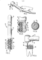
- the present dental reducing tool designated generally by the numeral 10 is adapted to be mounted in the chuck 12 of a dental handpiece 14 of convention construction.
- Dental handpiece 14 is operative to rotate the chuck 12 at high speed and is ordinarily provided with a nozzle 16 for directing streams of fluid, usually comprising water or water and air, upon the reducing tool 10 and the tooth area for cooling the latter and washing away grinding debris which may fall on the cutting surface of the reducing tool.
- the reducing tool 10 of the present invention comprises a shaft 18 having a generally cylindrical end 22 adapted for detachable frictional engagement with the chuck 12 of the handpiece 14 and a grooved shank portion 20 at its opposite end, forming a plurality of coaxial circular grinding or reducing elements 24 spaced along the length of shank portion 20.
- shank portion 20 is illustrated as having six grooves forming seven reducing elements 24; it is to be understood, however, that more or less reducing elements 24 may be provided in accordance with particular requirements.
- Shaft 18 may be formed of steel or other appropriate material.
- the surfaces of the grinding elements 24 and the grooves 25 separating the elements 24 may be coated with a uniform layer 27 of abrasive material such as diamond particles embedded in a metal base as shown in FIG. 2.
- abrasive material such as diamond particles embedded in a metal base as shown in FIG. 2.
- the composition and method of application of such abrasive layer to the cutting surfaces of shank 20 is well known and hence need not be described herein.
- reducing tool 10 may then be moved to-and-fro in a plane parallel-to the longitudinal.axis of the shank 20 in the direction of arrow 23 so that the side wall 24b of elements 24 clear away the remaining ridges 26a in a lateral grinding action thereby providing a clean tooth surface 28.
- reducing tool 10 may be replaced by a straight taper reducing tool 21 to clear away the ridges 26a as shown in FIG. 6.
- the stream of fluid applied by nozzel 16 causes the tooth debris to be easily flushed away from the tooth surface as well as from the surface of the reducing elements 24.
- the reducing tool 10 of FIGS. 2 and 3 provides optimum ease of penetration of the tooth substrate 26 with minimal generation of heat on the tooth structure and facilitates flushing of tooth debris from the work surfaces.
- the abrasive coated reducing elements 24 have curved ridges 24a and side walls 24b which taper away from each other in the direction of the shaft rotation axis and the grooves 25 have curved bottom walls 29.
- the rounded and tapered crests 24a of elements 24 provide easy gradually-widening penetration of tooth substrate 26 thereby minimizing frictional contact resistance with the tooth surface and attendant heat build up.
- the rounded bottom walls 29 and tapered sidewalls 24b of grooves 25 tend to prevent tooth debris from embedding therein and clogging the grinding tool and, furthermore, facilitates the easy and complete removal of any such debris which may have accumulated during the grinding operation, by the flushing action of the cleansing and cooling fluid stream from nozzle 16;
- both elements 24 and grooves 25 both have tapering side walls and curved crests and bottom walls respectively, it should be understood that the respective degrees of taper and crest and bottom wall widths may differ.
- the width of element 24 may be narrower than the corresponding grooves 25 to provide quicker penetration of very hard tooth structure with less pressure while provided less opportunity for the buildup of potentially clogging debris in the grooves 25.
- FIG. 7 Another embodiment of the present invention is illustrated in FIG. 7 which may be considered as a variant of the reducing tool 10 of FIGS. 2 and 3'.
- the reducing tool 30 comprises reducing elements 32 in the form of flat discs having substantially parallel side wails 34 and circularly rounded groove bottom walls 36 formed in shank 37.
- elements 32 including the side walls 34 and groove bottom walls 36 are provided with a substantially uniform thickness coating 38 of abrasive material comprising diamond particles embedded in a metal base.
- the rims 40 of reducing elements 32 are relatively blunter than the rims 24a of the reducing elements 24, a feature which is useful in seme dental reducing applications, particularly when the dentist is cealing with a normal or standard tooth structure hardness.
- the reducing tool 50 is formed with circular reducing elements 52, each of which is axial cross-section has peripheral edges or rims 54 which are substantially flat, and side walls 56 which taper inwardly toward the axis of rotation of shank 58 for a major portion of their length and then continue into the circularly rounded groove inner walls 60 of adjacent grooves .62.
- the reducing tool 50 of Fig. 8 is particularly effective in use on soft tooth structure to provide greater reducing action while the rounded groove inner walls 60, as before, prevent an accumulation of tooth debris in the tool and facilitate removal of any such debris by the action of the cleaning and cooling fluid stream from nozzle 16.
- the reducing tool 70 comprises reducing elements 72 each of which in cross-section has substantially flat rim 74, the edges 76 of which are rounded, and a similarly shaped groove inner wall; i.e. having a slightly rounded surface 78 and gently rounded end portions 80.
- the side walls 82 of elements 72 taper inwardly toward the axis of rotation of shank 84.
- the reducing tool of Fig. 9 is suitable for use on quite soft tooth structure and then layer of enamel and dentin for maximum reduction capability.
- the grinding tools 50 and 70 of Figs. 8 and 9 may be provided with a coating 36 of abrasive material comprising diamond particles embedded in a metal base.
- the reducing tool 90 has a single helical groove 92 with a rounded bottom wall 94.
- the grooves define a helical thread which acts as a reducing element and, as in the previous embodiment, is coated with an abrasive material comprising diamond particles embedded in a base metal.
- the rounded bottom wall of the groove in the reducing tools of the invention not only reduces the accumulation of tooth debris but avoids the weakening which would result from the presence of sharp corners.
- the bottom wall of the groove lies at the point of minimum diameter and therefore minimum strength. Sharp corners at this point tend not only to concentrate the stresses at the point of weakness but also facilitate crack propagation with a resulting substantial weakening of the shank.
- the present invention is not limited to reducing tools having reducing elements of uniform diameter, i.e. overall cylindrical shape in radial cross-section of the shank.
- the invention may be embodied in reducing tools of the character described above having in radial cross-section of the shank, various shapes such as spheroidal or ellipsoidal shapes.
Applications Claiming Priority (2)
| Application Number | Priority Date | Filing Date | Title |
|---|---|---|---|
| US06/067,794 US4264307A (en) | 1979-08-20 | 1979-08-20 | Dental reducing tool |
| US67794 | 2005-02-28 |
Publications (1)
| Publication Number | Publication Date |
|---|---|
| EP0025645A1 true EP0025645A1 (fr) | 1981-03-25 |
Family
ID=22078453
Family Applications (1)
| Application Number | Title | Priority Date | Filing Date |
|---|---|---|---|
| EP80302812A Withdrawn EP0025645A1 (fr) | 1979-08-20 | 1980-08-14 | Instrument à meuler dentaire |
Country Status (4)
| Country | Link |
|---|---|
| US (1) | US4264307A (fr) |
| EP (1) | EP0025645A1 (fr) |
| JP (1) | JPS5631744A (fr) |
| ES (1) | ES263050Y (fr) |
Cited By (6)
| Publication number | Priority date | Publication date | Assignee | Title |
|---|---|---|---|---|
| WO1982002827A1 (fr) * | 1981-02-17 | 1982-09-02 | Plischka Gerhard | Corps de meulage diamante |
| EP0159308A1 (fr) * | 1984-03-21 | 1985-10-23 | Fernand Eeckman | Outil rotatif et méthode pour la confection de protheses totales en resine synthetique |
| EP0229620A3 (en) * | 1986-01-06 | 1987-08-26 | Advanced Technology Laboratories, Inc. | Transluminal microdissection device |
| FR2639216A1 (fr) * | 1988-11-23 | 1990-05-25 | Truche Francis | Fraise rotative pour applications dentaires |
| DE10030434B4 (de) * | 2000-06-21 | 2007-04-05 | Gebr. Brasseler Gmbh & Co. Kg | Dental-Schleifwerkzeug |
| WO2011115339A1 (fr) * | 2010-03-17 | 2011-09-22 | 주식회사 이비아이 | Fraise pour os alvéolaire |
Families Citing this family (16)
| Publication number | Priority date | Publication date | Assignee | Title |
|---|---|---|---|---|
| US4634379A (en) * | 1979-09-17 | 1987-01-06 | Syntex (U.S.A.) Inc. | Abrasive dental tool |
| FR2481105A1 (fr) * | 1980-04-25 | 1981-10-30 | Rigaud Michel | Procede et outillage pour la standardisation de la preparation des dents en vue de la pose des couronnes |
| JPS6171106U (fr) * | 1984-10-17 | 1986-05-15 | ||
| CA1293663C (fr) * | 1986-01-06 | 1991-12-31 | David Christopher Auth | Appareil de micro-dissection intravasculaire |
| US5080588A (en) * | 1988-06-27 | 1992-01-14 | The University Of Michigan | Surface finishing apparatus and method |
| US5273559A (en) * | 1991-08-30 | 1993-12-28 | Minnesota Mining And Manufacturing Company | Abrasive dental articles |
| US5584843A (en) * | 1994-12-20 | 1996-12-17 | Boston Scientific Corporation | Shaped wire multi-burr rotational ablation device |
| US5766190A (en) * | 1995-05-24 | 1998-06-16 | Boston Scientific Corporation Northwest Technology Center, Inc. | Connectable driveshaft system |
| US6579096B2 (en) * | 2000-08-08 | 2003-06-17 | Paul C. Chiu | Method and system for selectively staining dental composite resin |
| US7021933B2 (en) * | 2003-12-11 | 2006-04-04 | Caldwell Mark J | Universal depth cut burr having dental and skeletal applications |
| US20070238068A1 (en) * | 2006-04-06 | 2007-10-11 | Isaac Comfortes | Self-limiting depth gauge spherical dental burr and method of use |
| US20100262175A1 (en) * | 2009-04-14 | 2010-10-14 | Warsaw Orthopedic, Inc. | Minimally invasive instrument and methods to treat periodontal disease |
| US8696954B2 (en) * | 2010-06-09 | 2014-04-15 | Tanaka Dental Products | Method, system, and composition for coloring ceramics |
| US9629646B2 (en) | 2012-07-11 | 2017-04-25 | Jens Kather | Curved burr surgical instrument |
| IL230833A0 (en) * | 2014-02-05 | 2014-09-30 | Ophir Fromovich | bone graft |
| JP7210167B2 (ja) * | 2018-06-25 | 2023-01-23 | マニー株式会社 | 咬合面形成用バー |
Citations (6)
| Publication number | Priority date | Publication date | Assignee | Title |
|---|---|---|---|---|
| DE566538C (de) * | 1931-02-13 | 1932-12-17 | Friedrich Bertololy | Zahnaerztliches Werkzeug zum Bohren und Fraesen |
| GB916197A (en) * | 1960-05-10 | 1963-01-23 | Peter Brasseler | Drill for dental purposes or the like |
| DE1294592B (de) * | 1962-05-17 | 1969-05-08 | Hopf Ringleb & Co | Mit Diamantkorn bestuecktes Bohr- und Schleifwerkzeug fuer zahnaerztliche Zwecke, vorzugsweise fuer hoehere Drehzahlbereiche |
| US3894339A (en) * | 1974-07-03 | 1975-07-15 | Walter E Manzi | Dental tool |
| US4058898A (en) * | 1976-03-19 | 1977-11-22 | Star Dental Manufacturing Co., Inc. | Dental burr |
| DE2902399A1 (de) * | 1978-01-30 | 1979-08-02 | Star Dental Mfg Co | Zahnschleifwerkzeug |
Family Cites Families (3)
| Publication number | Priority date | Publication date | Assignee | Title |
|---|---|---|---|---|
| US2807264A (en) * | 1953-09-10 | 1957-09-24 | Albert C Tuck | Instruments for contouring bones |
| US2857671A (en) * | 1956-11-13 | 1958-10-28 | Milton E Nelson | Dental grinding instrument |
| NL7013165A (fr) * | 1970-09-05 | 1972-03-07 |
-
1979
- 1979-08-20 US US06/067,794 patent/US4264307A/en not_active Expired - Lifetime
-
1980
- 1980-08-14 EP EP80302812A patent/EP0025645A1/fr not_active Withdrawn
- 1980-08-19 ES ES1980263050U patent/ES263050Y/es not_active Expired
- 1980-08-20 JP JP11356880A patent/JPS5631744A/ja active Pending
Patent Citations (6)
| Publication number | Priority date | Publication date | Assignee | Title |
|---|---|---|---|---|
| DE566538C (de) * | 1931-02-13 | 1932-12-17 | Friedrich Bertololy | Zahnaerztliches Werkzeug zum Bohren und Fraesen |
| GB916197A (en) * | 1960-05-10 | 1963-01-23 | Peter Brasseler | Drill for dental purposes or the like |
| DE1294592B (de) * | 1962-05-17 | 1969-05-08 | Hopf Ringleb & Co | Mit Diamantkorn bestuecktes Bohr- und Schleifwerkzeug fuer zahnaerztliche Zwecke, vorzugsweise fuer hoehere Drehzahlbereiche |
| US3894339A (en) * | 1974-07-03 | 1975-07-15 | Walter E Manzi | Dental tool |
| US4058898A (en) * | 1976-03-19 | 1977-11-22 | Star Dental Manufacturing Co., Inc. | Dental burr |
| DE2902399A1 (de) * | 1978-01-30 | 1979-08-02 | Star Dental Mfg Co | Zahnschleifwerkzeug |
Cited By (6)
| Publication number | Priority date | Publication date | Assignee | Title |
|---|---|---|---|---|
| WO1982002827A1 (fr) * | 1981-02-17 | 1982-09-02 | Plischka Gerhard | Corps de meulage diamante |
| EP0159308A1 (fr) * | 1984-03-21 | 1985-10-23 | Fernand Eeckman | Outil rotatif et méthode pour la confection de protheses totales en resine synthetique |
| EP0229620A3 (en) * | 1986-01-06 | 1987-08-26 | Advanced Technology Laboratories, Inc. | Transluminal microdissection device |
| FR2639216A1 (fr) * | 1988-11-23 | 1990-05-25 | Truche Francis | Fraise rotative pour applications dentaires |
| DE10030434B4 (de) * | 2000-06-21 | 2007-04-05 | Gebr. Brasseler Gmbh & Co. Kg | Dental-Schleifwerkzeug |
| WO2011115339A1 (fr) * | 2010-03-17 | 2011-09-22 | 주식회사 이비아이 | Fraise pour os alvéolaire |
Also Published As
| Publication number | Publication date |
|---|---|
| ES263050Y (es) | 1983-03-01 |
| US4264307B1 (fr) | 1987-06-02 |
| JPS5631744A (en) | 1981-03-31 |
| US4264307A (en) | 1981-04-28 |
| ES263050U (es) | 1982-08-01 |
Similar Documents
| Publication | Publication Date | Title |
|---|---|---|
| EP0025645A1 (fr) | Instrument à meuler dentaire | |
| US4389192A (en) | Dental reducing tool | |
| US5735689A (en) | Endodontic dental instrument | |
| EP0893973B1 (fr) | Instrument endodontique | |
| US7094056B2 (en) | Endodontic instrument having reversed helix | |
| US6872125B2 (en) | Tool for smoothing a workpiece | |
| US6179616B1 (en) | Dental drill | |
| US3894339A (en) | Dental tool | |
| US6419488B1 (en) | Endodontic instrument having a chisel tip | |
| US5980250A (en) | Endodontic instrument | |
| US20040023187A1 (en) | Ultrasonic surgical dental tool and method of making same | |
| JP4382666B2 (ja) | 歯内治療器具 | |
| JP2007229474A (ja) | 可変の蔓巻角を有する歯内治療用ヤスリ | |
| EP0444155B1 (fr) | Outils d'alesage dentaires | |
| US7311522B2 (en) | Endodontic instruments and method of manufacturing same | |
| US6126521A (en) | Process and apparatus for manufacturing endodontic instruments | |
| WO2002069830A1 (fr) | Instrument dentaire chirurgical ultrasonique equipe d'une extremite rapeuse | |
| US4634379A (en) | Abrasive dental tool | |
| EP1179997B1 (fr) | Outil abrasif comportant une zone active et une zone de securite | |
| JP2001526553A (ja) | のみ先端部を有する歯内処置器具 | |
| JPS63318937A (ja) | 歯科用高速切削具 | |
| JPS6142580Y2 (fr) | ||
| JPH0438423B2 (fr) | ||
| JPH0679634A (ja) | 研削用加工具 |
Legal Events
| Date | Code | Title | Description |
|---|---|---|---|
| PUAI | Public reference made under article 153(3) epc to a published international application that has entered the european phase |
Free format text: ORIGINAL CODE: 0009012 |
|
| AK | Designated contracting states |
Designated state(s): AT BE CH DE FR GB IT LU NL SE |
|
| ITCL | It: translation for ep claims filed |
Representative=s name: VETTOR GALLETTI |
|
| TCAT | At: translation of patent claims filed | ||
| DET | De: translation of patent claims | ||
| 17P | Request for examination filed |
Effective date: 19810924 |
|
| STAA | Information on the status of an ep patent application or granted ep patent |
Free format text: STATUS: THE APPLICATION IS DEEMED TO BE WITHDRAWN |
|
| 18D | Application deemed to be withdrawn |
Effective date: 19830516 |