EP0025372B1 - Groupe propulseur à transmissions hydrostatiques assurant la translation et la direction avec recyclage hydraulique de puissance en virage - Google Patents
Groupe propulseur à transmissions hydrostatiques assurant la translation et la direction avec recyclage hydraulique de puissance en virage Download PDFInfo
- Publication number
- EP0025372B1 EP0025372B1 EP80401161A EP80401161A EP0025372B1 EP 0025372 B1 EP0025372 B1 EP 0025372B1 EP 80401161 A EP80401161 A EP 80401161A EP 80401161 A EP80401161 A EP 80401161A EP 0025372 B1 EP0025372 B1 EP 0025372B1
- Authority
- EP
- European Patent Office
- Prior art keywords
- motor
- pump
- drive
- travel
- vehicle
- Prior art date
- Legal status (The legal status is an assumption and is not a legal conclusion. Google has not performed a legal analysis and makes no representation as to the accuracy of the status listed.)
- Expired
Links
Images


Classifications
-
- B—PERFORMING OPERATIONS; TRANSPORTING
- B62—LAND VEHICLES FOR TRAVELLING OTHERWISE THAN ON RAILS
- B62D—MOTOR VEHICLES; TRAILERS
- B62D11/00—Steering non-deflectable wheels; Steering endless tracks or the like
- B62D11/02—Steering non-deflectable wheels; Steering endless tracks or the like by differentially driving ground-engaging elements on opposite vehicle sides
- B62D11/06—Steering non-deflectable wheels; Steering endless tracks or the like by differentially driving ground-engaging elements on opposite vehicle sides by means of a single main power source
- B62D11/10—Steering non-deflectable wheels; Steering endless tracks or the like by differentially driving ground-engaging elements on opposite vehicle sides by means of a single main power source using gearings with differential power outputs on opposite sides, e.g. twin-differential or epicyclic gears
- B62D11/14—Steering non-deflectable wheels; Steering endless tracks or the like by differentially driving ground-engaging elements on opposite vehicle sides by means of a single main power source using gearings with differential power outputs on opposite sides, e.g. twin-differential or epicyclic gears differential power outputs being effected by additional power supply to one side, e.g. power originating from secondary power source
- B62D11/18—Steering non-deflectable wheels; Steering endless tracks or the like by differentially driving ground-engaging elements on opposite vehicle sides by means of a single main power source using gearings with differential power outputs on opposite sides, e.g. twin-differential or epicyclic gears differential power outputs being effected by additional power supply to one side, e.g. power originating from secondary power source the additional power supply being supplied hydraulically
Definitions
- the technical sector of the present invention is that of transmissions for tracked vehicles or with non-steerable wheels and more particularly hydrostatic transmissions applicable to battle tanks or to public works vehicles.
- This type of construction requires a significant increase in the apparent power of the hydraulic elements so as to be able to transmit sufficient power in the bend on the track or the wheel requiring the most torque or speed, this in order to ensure good mobility when driving. 'contraption.
- This second type of construction which has the advantage of power transfer mechanically from one track to the other when cornering, is nevertheless characterized by less mobility than that which could be obtained by hydrostatic transmission.
- this type of device causes a discontinuity in the transmission of power when cornering, which is due to the shifting of the gears of the mechanical gearbox.
- vehicles comprising this type of device have turning radii which are directly dependent on the speed engaged, the turning being effected by combination of a translational speed obtained by a transmission including the mechanical gearbox, and d '' an increase in speed brought to a track by the hydrostatic transmission, accompanied by a reduction in speed on the other track.
- the present invention therefore aims to eliminate the aforementioned drawbacks by managing to achieve a continuous translation and direction transmission while ensuring recycling by hydraulic means between tracks or between wheels of the vehicle.
- the invention aims to obtain good performance both in a straight line and in a bend on a tracked or non-steerable vehicle fully equipped with hydrostatic transmissions without increasing the apparent power of the components defined on the basis of the requirements inherent in the mobility of the vehicle in a straight line.
- each hydrostatic translation transmission consists of at least one variable displacement pump (3a, 3b) supplying, by means of a fluid distribution circuit, each respectively, at least a first hydraulic motor and at least one variable displacement pump motor mounted respectively on either side of the vehicle, each first motor of each translation transmission being mechanically linked to each pump motor of the transmission located on the opposite side on the vehicle.
- the fluid distribution circuit of each translation transmission comprises at least one linear or rotary distributor with two positions, a first position allowing the pump motor of said transmission to be supplied with fluid, and a second position enabling the motor to be supplied -pump of opposite transmission.
- the distributor of each translation transmission comprises a control system allowing the passage from the first to the second position of the distributor when the displacement of the pump motor of said transmission changes from a positive displacement ( engine operation) to a negative displacement (pump operation), the reverse variation of displacement causing the passage from the second to the first position of the distributor.
- the steering transmission is composed of a variable displacement pump with two flow directions sucking fluid into the high pressure loop in a straight line of one of the translation transmissions becoming low pressure loop when cornering, this transmission being on the side inside, to deliver it into the high pressure loop of the translation transmission located on the opposite side of the vehicle.
- the steering transmission comprises a linear or rotary distributor with two positions for reversing the direction of distribution of the fluid supplied by the pump of said transmission during the operation of the vehicle in reverse.
- each translational transmission comprises a first motor and two motor-pumps located on the side of the vehicle opposite the first motor, one of the motor-pumps being arranged in parallel in the hydraulic circuit on the first motor, and the other pump motor can be coupled in parallel on the first motor of either of the translation transmissions by means of a linear or rotary distributor with two positions, the passage of one to the other of the positions being controlled by the passage from positive displacement to negative displacement of said motor-pump.
- each translation transmission comprises a first motor and two motor-pumps located on the side of the vehicle opposite to the first motor, each motor-pump being able to be coupled in parallel in the hydraulic circuit on the first motor of either of the translation transmissions by a linear or rotary distributor with two positions, the passage from one to the other of the positions of each distributor being controlled by the passage from positive displacement to displacement negative of the corresponding pump motor.
- the pump motors of each transmission are connected to each other and to the first motor of the other transmission by mechanical means.
- variable displacement pumps of each translation transmission are controlled by tachometric regulations from the speed of the generation to which are superimposed regulations with algebraic summation of power by pressure.
- variable displacement pump motors are controlled by tachometric regulations from their drive speed by the gypsies to which are superimposed for pump pump motor operation, algebraic summation power regulations by pressure.
- the device shown in Figure 1, according to the first embodiment therefore comprises two hydrostatic translation transmissions driven by a heat engine 1 by means of a gear train 2, 2a, 2b.
- the output shafts of the gears 2a and 2b respectively control the rotation of two variable displacement pumps 3a and 3b.
- the pump 3a (respectively 3b) supplies fluid to a first motor 4a (respectively 4b) and hydraulically in parallel thereto a second motor 5a (respectively 5b).
- the second engine of each transmission is located on the vehicle on the opposite side to the transmission to which it belongs and is mechanically connected to the first engine of the opposite transmission.
- the transmission (pump 3a, first engine 4a) located on the left side of the vehicle (not shown) has its second engine 5a located on the right side of the vehicle and connected by a mechanical reducer 6b to the first engine 4b of the right transmission (pump 3b, first motor 4b and second motor 5b).
- the second motor 5b of the second translation transmission is linked by a mechanical reducer 6a to the first motor 4a.
- the hydraulic circuit supplying the motor-pump of each transmission comprises a distributor (respectively 7a and 7b) with two positions, of the linear or rotary type.
- variable displacement pump motor is by example of the axial piston type, in which case the variation in displacement can be obtained by modifying the inclination of the plate on which the pistons are supported.
- a control device authorizes the change of position of the distributor of said transmission.
- the distributor 7a is controlled by the passage to zero (or in the vicinity of zero) of the displacement of the pump motor 5a while the distributor 7b is controlled by the pump motor 5b.
- the device is completed by a steering pump 8 driven by the motor 1 by means of the distribution box containing the gear 2 and it is hydraulically connected to the high pressure branches of each of the translation transmissions.
- the pump 8 is equipped with a distributor 9 with two positions allowing the reversal of fluid direction to exercise the direction function in reverse.
- the pump motors Sa and 5b are of maximum displacement and operate as an engine.
- the distributors 7a and 7b are in their second position (not shown in FIG. 1) and the pump 3a (respectively 3b) supplies the motors 4a and 5b (respectively 4b and 5a).
- the pump motors 5a and 5b operate as a pump, and in the case for example of a left turn, the motor 4a is driven by the left gypsy which has become leading. It then operates as a pump and supplies the pumps 3a and 5a which have become motors.
- the pump 3a which has become a motor mechanically drives, via the distribution box, the pumps 3b and 8 which supply the motor 4b.
- the pump 5b also supplies the motor 4b.
- the power generation provides additional energy to the outside sprocket when cornering.
- the force available on the external gypsy then increases from its minimum for the zero displacement of the pump motors to a maximum value for the maximum displacement of the pump motors.
- the steering pump makes it possible to partially or entirely transmit the unused power of the power generation and to maintain the initial speed by providing additional flow to the external receivers. Indeed, it then sucks fluid into the high pressure loop which has become a low pressure loop turn on the inside of the turn, to discharge it on the high pressure loop to the receiver located on the outside of the turn.
- This first embodiment of the invention has the characteristic of a torque gira - Maximum tion to the judgment of the vehicle to turn in place or the vehicle is started, which then decreases until the speed corresponding to the point where motor-pumps are of zero displacement to increase again to a maximum then, taking into account the significant effort necessary for the translation at high speed, to decrease very slightly until the maximum speed of the vehicle in a straight line.
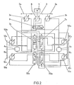
- FIG. 2 which represents an alternative embodiment of the first type in FIG. 1
- the single pump motor of each translation transmission has been replaced by two pump motors 50a and 51a (respectively 50b and 51b) identical.
- This embodiment has the advantage of allowing a phase shift in the displacement of the two motor-pumps which makes it possible to increase the minimum value of the turning torque and obtain it.
- This embodiment differs from the first embodiment described in that it comprises, for each translational transmission, in addition to the two pump-motors 50a and 51 (respectively 50b and 51b), two distributors 7a and 70a (respectively 7b and 70b) whose change of position is controlled by the passage at zero displacement of the motors- respective pumps mentioned above.
- the two pump motors of each transmission are interconnected and linked to the first motor of the opposite transmission by mechanical means constituted by a gear train 10a, 11a, 12a (respectively 10b, 11b, 12b) .
- tachometric regulations are used to control the displacements of the hydraulic motor-pumps 50a, 50b, 51a and 51b from their drive speed so as to keep the same displacement, avoiding the drop in speed of the vehicle that would cause the increase in the displacement of the motor-pumps linked to pressure regulation.
- the references of the members will be used without their literal indices when the operation described is valid on one side or the other of the vehicle.
- the motor-pump 50 on the interior side will mean the motor-pump 50a if the turn is made to the right or the motor-pump 50b if the turn is made to the left.
- the two motor-pumps 50 and 51 of each transmission are motors, there is no direct transfer of power from one track to another.
- the transfer of power directly from one scale to another is carried out by the two fast motor-pumps 50 and 51.
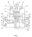
- the third embodiment shown in FIG. 6 constitutes a variant of the second embodiment shown in FIG. 2.
- the second pump motor 51 of each translation transmission is permanently hydraulically coupled to the fixed displacement hydraulic motor 4 mounted on the opposite gypsy while the first pump motor 50 has on its circuit the recycling distributor 7 described above which does not allow power recycling only when the first pump motor becomes a pump.
- the capacity of the first pump motor 50 is increased to the point of maximum pump operation and possibly that of the second pump motor 51 if it has not reached its maximum in the second phase.
- the advantage of such a device lies in the fact that the effort available on the external gypsy, minimal at start-up, thus increases during the first phase, is more or less constant during the second phase and increases during the last phase.
- Pressure regulation with algebraic power summation also makes it possible to keep large displacement values in the turning phase, which facilitates indirect recycling of power by the pumps.
- the steering pump with zero displacement in translation, is not provided with regulations but the value of its displacement will be controlled directly by the operator to perform the turning functions.
- the maximum engine displacement makes it possible to obtain the maximum torque at reduced speed of the vehicle. Simultaneously with the increase in the displacement of the pumps 3, it will be necessary to reduce the displacement of the elements 50 and 51 in engine operation to zero displacement and then to increase their displacement in pump operation to their maximums, these being reached simultaneously at the maximum displacement of the pumps 3.
- This joint variation in displacement of the various elements will allow the passage, by continuous variation, of the minimum speed of the vehicle at its maximum speed and of its maximum torque to its minimum torque. These variations will be controlled by tachometric regulations, either from the speed of rotation of the power generation, or preferably from the speed of the gypsies of the vehicle.
- the invention in each of its embodiments has the other advantage that in turns, the transfer of power by hydraulic means advantageously replaces mechanical transfer by reducing the mass of the assembly, by simplifying the installation of components and protecting the device from possible torque peaks, by the existence of valves mounted in a known manner on the hydrostatic transmission circuits.
- all of the devices, translation transmissions with direct hydraulic power transfer and steering pump, object of the invention makes it possible to benefit from the excellent mobility and continuity provided by hydrostatic transmission both online. right than in turns.
- it allows the torques required for good cornering behavior as a function of the forward speed of the vehicle and maintaining this speed when cornering.
- the invention therefore applies with interest to vehicles such as public works vehicles, or combat tanks for which it is desired to obtain high mobility both in a straight line and in turns without excessive increase in the mass of the vehicle.
Landscapes
- Engineering & Computer Science (AREA)
- Chemical & Material Sciences (AREA)
- Combustion & Propulsion (AREA)
- Transportation (AREA)
- Mechanical Engineering (AREA)
- Motor Power Transmission Devices (AREA)
- Non-Deflectable Wheels, Steering Of Trailers, Or Other Steering (AREA)
Applications Claiming Priority (2)
| Application Number | Priority Date | Filing Date | Title |
|---|---|---|---|
| FR7922518A FR2464869A1 (fr) | 1979-09-10 | 1979-09-10 | Groupe propulseur a transmissions hydrostatiques assurant la translation et la direction avec recyclage hydraulique de puissance en virage |
| FR7922518 | 1979-09-10 |
Publications (2)
| Publication Number | Publication Date |
|---|---|
| EP0025372A1 EP0025372A1 (fr) | 1981-03-18 |
| EP0025372B1 true EP0025372B1 (fr) | 1983-06-01 |
Family
ID=9229488
Family Applications (1)
| Application Number | Title | Priority Date | Filing Date |
|---|---|---|---|
| EP80401161A Expired EP0025372B1 (fr) | 1979-09-10 | 1980-08-07 | Groupe propulseur à transmissions hydrostatiques assurant la translation et la direction avec recyclage hydraulique de puissance en virage |
Country Status (3)
| Country | Link |
|---|---|
| EP (1) | EP0025372B1 (enExample) |
| DE (1) | DE3063612D1 (enExample) |
| FR (1) | FR2464869A1 (enExample) |
Families Citing this family (8)
| Publication number | Priority date | Publication date | Assignee | Title |
|---|---|---|---|---|
| GB2246844A (en) * | 1990-07-13 | 1992-02-12 | Glowreach Limited | Vehicle with auxiliary drive system |
| FR2705639B1 (fr) * | 1993-05-24 | 1995-07-21 | France Etat Armement | Véhicule à transmission hydrostatique et à direction par roues directrices et dérapage. |
| DE19833942C2 (de) | 1998-07-28 | 2000-06-08 | Brueninghaus Hydromatik Gmbh | Hydrostatischer Fahrantrieb mit Differentialsperre |
| DE10128589C1 (de) * | 2001-06-13 | 2003-07-03 | Brueninghaus Hydromatik Gmbh | Hydrostatischer Antrieb |
| DE10356155B4 (de) * | 2003-12-02 | 2006-06-14 | Brueninghaus Hydromatik Gmbh | Hydrostatisches Antriebssystem mit pumpenseitiger Hydraulikfluidmengenteilung |
| DE102004061557B4 (de) * | 2004-12-21 | 2006-12-14 | Brueninghaus Hydromatik Gmbh | Hydrostatischer Fahrantrieb mit Differentialsperrwirkung |
| DE102011105440A1 (de) * | 2011-06-24 | 2012-12-27 | Robert Bosch Gmbh | Hydrostatischer Fahrantrieb |
| EP3378736B1 (de) * | 2017-03-20 | 2020-04-29 | Repaircraft PLC | Antriebssystem für kettenfahrzeuge und kettengetriebene arbeitsmaschinen sowie verfahren zur steuerung eines antriebssystems für kettenfahrzeuge und kettengetriebene arbeitsmaschinen |
Citations (1)
| Publication number | Priority date | Publication date | Assignee | Title |
|---|---|---|---|---|
| FR2445258A1 (fr) * | 1978-12-26 | 1980-07-25 | France Etat | Groupe propulseur hydraulique pour vehicule, a recyclage mecanique de puissance en virage |
Family Cites Families (13)
| Publication number | Priority date | Publication date | Assignee | Title |
|---|---|---|---|---|
| DE957184C (de) * | 1952-08-22 | 1957-01-31 | Hydromatic G M B H | Raupenfahrzeugantrieb |
| US3081647A (en) * | 1957-02-27 | 1963-03-19 | Fairchild Stratos Corp | Regenerative steering |
| GB863560A (en) * | 1958-10-08 | 1961-03-22 | Brown David Ind Ltd | New or improved power transmission means for vehicles |
| US3368425A (en) * | 1965-05-27 | 1968-02-13 | Gen Electric | Steering and driving power system |
| US3575066A (en) * | 1969-09-23 | 1971-04-13 | Gen Motors Corp | Transmission |
| US3744584A (en) * | 1971-04-29 | 1973-07-10 | Int Harvester Co | Hydrostatic transmission motors and coordinating clutch for same |
| US3774401A (en) * | 1972-06-26 | 1973-11-27 | Cmi Corp | Automatic control system for use with a hydraulic drive system |
| US3862668A (en) * | 1973-06-13 | 1975-01-28 | Eaton Corp | Hydrostatic transmission control system |
| DE2446727A1 (de) * | 1974-09-30 | 1976-04-15 | Serck Industries Ltd | Lenkungssystem fuer ein kettenfahrzeug |
| US4019596A (en) * | 1975-12-30 | 1977-04-26 | Sundstrand Corporation | Synchronous control system |
| US4024710A (en) * | 1976-03-25 | 1977-05-24 | Koehring Company | Load sensing hydraulic circuit having power matching means |
| US4086767A (en) * | 1977-01-24 | 1978-05-02 | Commercial Shearing, Inc. | Track drive circuits with synchronization and steering systems |
| GB1559225A (en) * | 1977-02-02 | 1980-01-16 | Caterpillar Tractor Co | Hydrostatic transmission with differential steering |
-
1979
- 1979-09-10 FR FR7922518A patent/FR2464869A1/fr active Granted
-
1980
- 1980-08-07 DE DE8080401161T patent/DE3063612D1/de not_active Expired
- 1980-08-07 EP EP80401161A patent/EP0025372B1/fr not_active Expired
Patent Citations (1)
| Publication number | Priority date | Publication date | Assignee | Title |
|---|---|---|---|---|
| FR2445258A1 (fr) * | 1978-12-26 | 1980-07-25 | France Etat | Groupe propulseur hydraulique pour vehicule, a recyclage mecanique de puissance en virage |
Also Published As
| Publication number | Publication date |
|---|---|
| FR2464869B1 (enExample) | 1984-01-06 |
| FR2464869A1 (fr) | 1981-03-20 |
| EP0025372A1 (fr) | 1981-03-18 |
| DE3063612D1 (en) | 1983-07-07 |
Similar Documents
| Publication | Publication Date | Title |
|---|---|---|
| EP2951436B1 (fr) | Moteur pompe hydraulique a cylindrée fixe ou variable | |
| EP2981426B1 (fr) | Dispositif de transmission hydraulique. | |
| EP0025372B1 (fr) | Groupe propulseur à transmissions hydrostatiques assurant la translation et la direction avec recyclage hydraulique de puissance en virage | |
| FR2629171A1 (fr) | Dispositif de transmission hydrostatique et application a un groupe motopropulseur ou un vehicule automobile | |
| FR2973302A1 (fr) | Vehicule comportant une chaine de traction hybride thermique/hydraulique a repartition de puissance | |
| EP0026115B1 (fr) | Transmissions hydrostatiques de puissance à grande plage de fonctionnement | |
| FR2970908A1 (fr) | Chaine de traction d'un vehicule hybride | |
| EP2817164B1 (fr) | Module hydraulique compact pour véhicule hybride hydraulique | |
| EP2376769A2 (fr) | Circuit de transmission hydraulique | |
| EP1934471B1 (fr) | Dispositif de gestion de la cylindree d'un moteur hydraulique ou d'un groupe de moteurs hydrauliques | |
| EP0013190B2 (fr) | Groupe propulseur hydraulique pour véhicule à recyclage mécanique de puissance en virage | |
| WO2015189324A1 (fr) | Procede d'activation d'une assistance hydraulique d'un systeme de transmission de vehicule | |
| EP2817167B1 (fr) | Module hydraulique compact pour véhicule hybride hydraulique | |
| FR2697883A1 (fr) | Ensemble hydromécanique d'entraînement. | |
| FR2705639A1 (fr) | Véhicule à transmission hydrostatique et à direction par roues directrices et dérapage. | |
| WO2023118755A1 (fr) | Dispositif et procede de commande pour une transmission electrohydraulique | |
| EP2643584A1 (fr) | Machine hydraulique a cylindree variable, notamment pour vehicule automobile | |
| WO2014087019A1 (fr) | Transmission hydrostatique de véhicule avec engagement de moteurs selon leurs plages de fonctionnement optimales | |
| EP3824205B1 (fr) | Circuit d'assistance hydraulique comprenant des moyens de gavage ameliores | |
| EP4453450B1 (fr) | Procede de mise en service pour une transmission electrohydraulique | |
| WO2011104383A1 (fr) | Dispositif de propulsion d'un vehicule avec recuperation et restitution d'energie | |
| WO2017098097A1 (fr) | Vehicule automobile a quatre roues motrices et a propulsion hybride comprenant un differentiel dote d'un module hydraulique | |
| FR3138485A1 (fr) | Transmission hydrostatique améliorée. | |
| FR3131254A1 (fr) | Ensemble de propulsion pour engin blinde motorise a au moins deux moteurs thermiques et engin associe. | |
| WO2016124828A1 (fr) | Ensemble de traction pour véhicule hybride comprenant une machine hydraulique disposée autour de l'arbre de sortie d'un différentiel |
Legal Events
| Date | Code | Title | Description |
|---|---|---|---|
| PUAI | Public reference made under article 153(3) epc to a published international application that has entered the european phase |
Free format text: ORIGINAL CODE: 0009012 |
|
| AK | Designated contracting states |
Designated state(s): CH DE GB SE |
|
| 17P | Request for examination filed |
Effective date: 19810407 |
|
| GRAA | (expected) grant |
Free format text: ORIGINAL CODE: 0009210 |
|
| AK | Designated contracting states |
Designated state(s): CH DE GB LI SE |
|
| REF | Corresponds to: |
Ref document number: 3063612 Country of ref document: DE Date of ref document: 19830707 |
|
| PLBE | No opposition filed within time limit |
Free format text: ORIGINAL CODE: 0009261 |
|
| STAA | Information on the status of an ep patent application or granted ep patent |
Free format text: STATUS: NO OPPOSITION FILED WITHIN TIME LIMIT |
|
| 26N | No opposition filed | ||
| EAL | Se: european patent in force in sweden |
Ref document number: 80401161.7 |
|
| PGFP | Annual fee paid to national office [announced via postgrant information from national office to epo] |
Ref country code: SE Payment date: 19990716 Year of fee payment: 20 |
|
| PGFP | Annual fee paid to national office [announced via postgrant information from national office to epo] |
Ref country code: GB Payment date: 19990727 Year of fee payment: 20 |
|
| PGFP | Annual fee paid to national office [announced via postgrant information from national office to epo] |
Ref country code: CH Payment date: 19990928 Year of fee payment: 20 |
|
| PGFP | Annual fee paid to national office [announced via postgrant information from national office to epo] |
Ref country code: DE Payment date: 19991022 Year of fee payment: 20 |
|
| PG25 | Lapsed in a contracting state [announced via postgrant information from national office to epo] |
Ref country code: LI Free format text: LAPSE BECAUSE OF EXPIRATION OF PROTECTION Effective date: 20000806 Ref country code: GB Free format text: LAPSE BECAUSE OF EXPIRATION OF PROTECTION Effective date: 20000806 Ref country code: CH Free format text: LAPSE BECAUSE OF EXPIRATION OF PROTECTION Effective date: 20000806 |
|
| PG25 | Lapsed in a contracting state [announced via postgrant information from national office to epo] |
Ref country code: SE Free format text: THE PATENT HAS BEEN ANNULLED BY A DECISION OF A NATIONAL AUTHORITY Effective date: 20000808 |
|
| REG | Reference to a national code |
Ref country code: GB Ref legal event code: PE20 Effective date: 20000806 |
|
| REG | Reference to a national code |
Ref country code: CH Ref legal event code: PL |
|
| EUG | Se: european patent has lapsed |
Ref document number: 80401161.7 |