EP0025372B1 - Hydrostatic-transmission propulsion unit for translation and power regenerative steering - Google Patents
Hydrostatic-transmission propulsion unit for translation and power regenerative steering Download PDFInfo
- Publication number
- EP0025372B1 EP0025372B1 EP80401161A EP80401161A EP0025372B1 EP 0025372 B1 EP0025372 B1 EP 0025372B1 EP 80401161 A EP80401161 A EP 80401161A EP 80401161 A EP80401161 A EP 80401161A EP 0025372 B1 EP0025372 B1 EP 0025372B1
- Authority
- EP
- European Patent Office
- Prior art keywords
- motor
- pump
- drive
- travel
- vehicle
- Prior art date
- Legal status (The legal status is an assumption and is not a legal conclusion. Google has not performed a legal analysis and makes no representation as to the accuracy of the status listed.)
- Expired
Links
Images


Classifications
-
- B—PERFORMING OPERATIONS; TRANSPORTING
- B62—LAND VEHICLES FOR TRAVELLING OTHERWISE THAN ON RAILS
- B62D—MOTOR VEHICLES; TRAILERS
- B62D11/00—Steering non-deflectable wheels; Steering endless tracks or the like
- B62D11/02—Steering non-deflectable wheels; Steering endless tracks or the like by differentially driving ground-engaging elements on opposite vehicle sides
- B62D11/06—Steering non-deflectable wheels; Steering endless tracks or the like by differentially driving ground-engaging elements on opposite vehicle sides by means of a single main power source
- B62D11/10—Steering non-deflectable wheels; Steering endless tracks or the like by differentially driving ground-engaging elements on opposite vehicle sides by means of a single main power source using gearings with differential power outputs on opposite sides, e.g. twin-differential or epicyclic gears
- B62D11/14—Steering non-deflectable wheels; Steering endless tracks or the like by differentially driving ground-engaging elements on opposite vehicle sides by means of a single main power source using gearings with differential power outputs on opposite sides, e.g. twin-differential or epicyclic gears differential power outputs being effected by additional power supply to one side, e.g. power originating from secondary power source
- B62D11/18—Steering non-deflectable wheels; Steering endless tracks or the like by differentially driving ground-engaging elements on opposite vehicle sides by means of a single main power source using gearings with differential power outputs on opposite sides, e.g. twin-differential or epicyclic gears differential power outputs being effected by additional power supply to one side, e.g. power originating from secondary power source the additional power supply being supplied hydraulically
Definitions
- the technical sector of the present invention is that of transmissions for tracked vehicles or with non-steerable wheels and more particularly hydrostatic transmissions applicable to battle tanks or to public works vehicles.
- This type of construction requires a significant increase in the apparent power of the hydraulic elements so as to be able to transmit sufficient power in the bend on the track or the wheel requiring the most torque or speed, this in order to ensure good mobility when driving. 'contraption.
- This second type of construction which has the advantage of power transfer mechanically from one track to the other when cornering, is nevertheless characterized by less mobility than that which could be obtained by hydrostatic transmission.
- this type of device causes a discontinuity in the transmission of power when cornering, which is due to the shifting of the gears of the mechanical gearbox.
- vehicles comprising this type of device have turning radii which are directly dependent on the speed engaged, the turning being effected by combination of a translational speed obtained by a transmission including the mechanical gearbox, and d '' an increase in speed brought to a track by the hydrostatic transmission, accompanied by a reduction in speed on the other track.
- the present invention therefore aims to eliminate the aforementioned drawbacks by managing to achieve a continuous translation and direction transmission while ensuring recycling by hydraulic means between tracks or between wheels of the vehicle.
- the invention aims to obtain good performance both in a straight line and in a bend on a tracked or non-steerable vehicle fully equipped with hydrostatic transmissions without increasing the apparent power of the components defined on the basis of the requirements inherent in the mobility of the vehicle in a straight line.
- each hydrostatic translation transmission consists of at least one variable displacement pump (3a, 3b) supplying, by means of a fluid distribution circuit, each respectively, at least a first hydraulic motor and at least one variable displacement pump motor mounted respectively on either side of the vehicle, each first motor of each translation transmission being mechanically linked to each pump motor of the transmission located on the opposite side on the vehicle.
- the fluid distribution circuit of each translation transmission comprises at least one linear or rotary distributor with two positions, a first position allowing the pump motor of said transmission to be supplied with fluid, and a second position enabling the motor to be supplied -pump of opposite transmission.
- the distributor of each translation transmission comprises a control system allowing the passage from the first to the second position of the distributor when the displacement of the pump motor of said transmission changes from a positive displacement ( engine operation) to a negative displacement (pump operation), the reverse variation of displacement causing the passage from the second to the first position of the distributor.
- the steering transmission is composed of a variable displacement pump with two flow directions sucking fluid into the high pressure loop in a straight line of one of the translation transmissions becoming low pressure loop when cornering, this transmission being on the side inside, to deliver it into the high pressure loop of the translation transmission located on the opposite side of the vehicle.
- the steering transmission comprises a linear or rotary distributor with two positions for reversing the direction of distribution of the fluid supplied by the pump of said transmission during the operation of the vehicle in reverse.
- each translational transmission comprises a first motor and two motor-pumps located on the side of the vehicle opposite the first motor, one of the motor-pumps being arranged in parallel in the hydraulic circuit on the first motor, and the other pump motor can be coupled in parallel on the first motor of either of the translation transmissions by means of a linear or rotary distributor with two positions, the passage of one to the other of the positions being controlled by the passage from positive displacement to negative displacement of said motor-pump.
- each translation transmission comprises a first motor and two motor-pumps located on the side of the vehicle opposite to the first motor, each motor-pump being able to be coupled in parallel in the hydraulic circuit on the first motor of either of the translation transmissions by a linear or rotary distributor with two positions, the passage from one to the other of the positions of each distributor being controlled by the passage from positive displacement to displacement negative of the corresponding pump motor.
- the pump motors of each transmission are connected to each other and to the first motor of the other transmission by mechanical means.
- variable displacement pumps of each translation transmission are controlled by tachometric regulations from the speed of the generation to which are superimposed regulations with algebraic summation of power by pressure.
- variable displacement pump motors are controlled by tachometric regulations from their drive speed by the gypsies to which are superimposed for pump pump motor operation, algebraic summation power regulations by pressure.
- the device shown in Figure 1, according to the first embodiment therefore comprises two hydrostatic translation transmissions driven by a heat engine 1 by means of a gear train 2, 2a, 2b.
- the output shafts of the gears 2a and 2b respectively control the rotation of two variable displacement pumps 3a and 3b.
- the pump 3a (respectively 3b) supplies fluid to a first motor 4a (respectively 4b) and hydraulically in parallel thereto a second motor 5a (respectively 5b).
- the second engine of each transmission is located on the vehicle on the opposite side to the transmission to which it belongs and is mechanically connected to the first engine of the opposite transmission.
- the transmission (pump 3a, first engine 4a) located on the left side of the vehicle (not shown) has its second engine 5a located on the right side of the vehicle and connected by a mechanical reducer 6b to the first engine 4b of the right transmission (pump 3b, first motor 4b and second motor 5b).
- the second motor 5b of the second translation transmission is linked by a mechanical reducer 6a to the first motor 4a.
- the hydraulic circuit supplying the motor-pump of each transmission comprises a distributor (respectively 7a and 7b) with two positions, of the linear or rotary type.
- variable displacement pump motor is by example of the axial piston type, in which case the variation in displacement can be obtained by modifying the inclination of the plate on which the pistons are supported.
- a control device authorizes the change of position of the distributor of said transmission.
- the distributor 7a is controlled by the passage to zero (or in the vicinity of zero) of the displacement of the pump motor 5a while the distributor 7b is controlled by the pump motor 5b.
- the device is completed by a steering pump 8 driven by the motor 1 by means of the distribution box containing the gear 2 and it is hydraulically connected to the high pressure branches of each of the translation transmissions.
- the pump 8 is equipped with a distributor 9 with two positions allowing the reversal of fluid direction to exercise the direction function in reverse.
- the pump motors Sa and 5b are of maximum displacement and operate as an engine.
- the distributors 7a and 7b are in their second position (not shown in FIG. 1) and the pump 3a (respectively 3b) supplies the motors 4a and 5b (respectively 4b and 5a).
- the pump motors 5a and 5b operate as a pump, and in the case for example of a left turn, the motor 4a is driven by the left gypsy which has become leading. It then operates as a pump and supplies the pumps 3a and 5a which have become motors.
- the pump 3a which has become a motor mechanically drives, via the distribution box, the pumps 3b and 8 which supply the motor 4b.
- the pump 5b also supplies the motor 4b.
- the power generation provides additional energy to the outside sprocket when cornering.
- the force available on the external gypsy then increases from its minimum for the zero displacement of the pump motors to a maximum value for the maximum displacement of the pump motors.
- the steering pump makes it possible to partially or entirely transmit the unused power of the power generation and to maintain the initial speed by providing additional flow to the external receivers. Indeed, it then sucks fluid into the high pressure loop which has become a low pressure loop turn on the inside of the turn, to discharge it on the high pressure loop to the receiver located on the outside of the turn.
- This first embodiment of the invention has the characteristic of a torque gira - Maximum tion to the judgment of the vehicle to turn in place or the vehicle is started, which then decreases until the speed corresponding to the point where motor-pumps are of zero displacement to increase again to a maximum then, taking into account the significant effort necessary for the translation at high speed, to decrease very slightly until the maximum speed of the vehicle in a straight line.
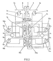
- FIG. 2 which represents an alternative embodiment of the first type in FIG. 1
- the single pump motor of each translation transmission has been replaced by two pump motors 50a and 51a (respectively 50b and 51b) identical.
- This embodiment has the advantage of allowing a phase shift in the displacement of the two motor-pumps which makes it possible to increase the minimum value of the turning torque and obtain it.
- This embodiment differs from the first embodiment described in that it comprises, for each translational transmission, in addition to the two pump-motors 50a and 51 (respectively 50b and 51b), two distributors 7a and 70a (respectively 7b and 70b) whose change of position is controlled by the passage at zero displacement of the motors- respective pumps mentioned above.
- the two pump motors of each transmission are interconnected and linked to the first motor of the opposite transmission by mechanical means constituted by a gear train 10a, 11a, 12a (respectively 10b, 11b, 12b) .
- tachometric regulations are used to control the displacements of the hydraulic motor-pumps 50a, 50b, 51a and 51b from their drive speed so as to keep the same displacement, avoiding the drop in speed of the vehicle that would cause the increase in the displacement of the motor-pumps linked to pressure regulation.
- the references of the members will be used without their literal indices when the operation described is valid on one side or the other of the vehicle.
- the motor-pump 50 on the interior side will mean the motor-pump 50a if the turn is made to the right or the motor-pump 50b if the turn is made to the left.
- the two motor-pumps 50 and 51 of each transmission are motors, there is no direct transfer of power from one track to another.
- the transfer of power directly from one scale to another is carried out by the two fast motor-pumps 50 and 51.
- the third embodiment shown in FIG. 6 constitutes a variant of the second embodiment shown in FIG. 2.
- the second pump motor 51 of each translation transmission is permanently hydraulically coupled to the fixed displacement hydraulic motor 4 mounted on the opposite gypsy while the first pump motor 50 has on its circuit the recycling distributor 7 described above which does not allow power recycling only when the first pump motor becomes a pump.
- the capacity of the first pump motor 50 is increased to the point of maximum pump operation and possibly that of the second pump motor 51 if it has not reached its maximum in the second phase.
- the advantage of such a device lies in the fact that the effort available on the external gypsy, minimal at start-up, thus increases during the first phase, is more or less constant during the second phase and increases during the last phase.
- Pressure regulation with algebraic power summation also makes it possible to keep large displacement values in the turning phase, which facilitates indirect recycling of power by the pumps.
- the steering pump with zero displacement in translation, is not provided with regulations but the value of its displacement will be controlled directly by the operator to perform the turning functions.
- the maximum engine displacement makes it possible to obtain the maximum torque at reduced speed of the vehicle. Simultaneously with the increase in the displacement of the pumps 3, it will be necessary to reduce the displacement of the elements 50 and 51 in engine operation to zero displacement and then to increase their displacement in pump operation to their maximums, these being reached simultaneously at the maximum displacement of the pumps 3.
- This joint variation in displacement of the various elements will allow the passage, by continuous variation, of the minimum speed of the vehicle at its maximum speed and of its maximum torque to its minimum torque. These variations will be controlled by tachometric regulations, either from the speed of rotation of the power generation, or preferably from the speed of the gypsies of the vehicle.
- the invention in each of its embodiments has the other advantage that in turns, the transfer of power by hydraulic means advantageously replaces mechanical transfer by reducing the mass of the assembly, by simplifying the installation of components and protecting the device from possible torque peaks, by the existence of valves mounted in a known manner on the hydrostatic transmission circuits.
- all of the devices, translation transmissions with direct hydraulic power transfer and steering pump, object of the invention makes it possible to benefit from the excellent mobility and continuity provided by hydrostatic transmission both online. right than in turns.
- it allows the torques required for good cornering behavior as a function of the forward speed of the vehicle and maintaining this speed when cornering.
- the invention therefore applies with interest to vehicles such as public works vehicles, or combat tanks for which it is desired to obtain high mobility both in a straight line and in turns without excessive increase in the mass of the vehicle.
Description
Le secteur technique de la présente invention est celui des transmissions pour véhicules chenillés ou à roues non directrices et plus particulièrement des transmissions hydrostatiques applicables à des chars de combat ou à des engins de travaux publics.The technical sector of the present invention is that of transmissions for tracked vehicles or with non-steerable wheels and more particularly hydrostatic transmissions applicable to battle tanks or to public works vehicles.
Dans ce domaine, des réalisations ont déjà été proposées. Ainsi, on a réalisé un véhicule à transmissions hydrostatiques indépendantes assurant la translation par vitesse identique sur les deux chenilles ou sur les deux groupes de roues et la direction par variation de la vitesse des chenilles ou des roues d'un côté par rapport à l'autre.In this area, achievements have already been proposed. Thus, a vehicle with independent hydrostatic transmissions has been produced ensuring the translation by identical speed on the two tracks or on the two groups of wheels and the steering by variation of the speed of the tracks or of the wheels on one side with respect to the other.
Ce type de réalisations nécessite une augmentation importante de la puissance apparente des éléments hydrauliques de façon à pouvoir transmettre en virage une puissance suffisante sur la chenille ou la roue nécessitant le plus de couple ou de vitesse, ceci afin d'assurer une bonne mobilité à l'engin.This type of construction requires a significant increase in the apparent power of the hydraulic elements so as to be able to transmit sufficient power in the bend on the track or the wheel requiring the most torque or speed, this in order to ensure good mobility when driving. 'contraption.
Ce surdimensionnement grève le poids de la transmission et par-là même diminue le rendement en translation pure, pendant laquelle le surcroît de puissance nécessitant cette augmentation de puissance apparente n'est pas utilisé.This oversizing strikes the weight of the transmission and thereby decreases the efficiency in pure translation, during which the additional power requiring this increase in apparent power is not used.
En outre l'encombrement important de ce type de transmissions accroît les difficultés d'implantation sur le véhicule.In addition, the large size of this type of transmission increases the installation difficulties on the vehicle.
D'autres types de véhicules, en particulier des véhicules de travaux publics à vitesse lente de translation, sont équipés d'une boîte de vitesses mécanique et d'une transmission hydrostatique de direction. Le transfert de la puissance en virage se fait alors par voie mécanique, la transmission de translation étant alors mécanique et discontinue.Other types of vehicles, in particular public works vehicles with low travel speed, are fitted with a mechanical gearbox and a hydrostatic steering transmission. The transfer of power when cornering is then done mechanically, the translational transmission then being mechanical and discontinuous.
Ce second type de réalisations, qui présente l'avantage d'un transfert de puissance par voie mécanique d'une chenille sur l'autre en virage, est néanmoins caractérisé par une mobilité inférieure à celle qui pourrait être obtenue par une transmission hydrostatique. En particulier, ce genre de dispositifs provoque une discontinuité de la transmission de puissance en virage, qui est due au passage des vitesses de la boîte mécanique. En outre, les engins comportant ce genre de dispositifs ont des rayons de virage qui sont directement fonction de la vitesse engagée, le virage s'effectuant par combinaison d'une vitesse de translation obtenue par une transmission incluant la boîte à vitesse mécanique, et d'un surcroît de vitesse apporté à une chenille par la transmission hydrostatique, accompagné d'une diminution de vitesse sur l'autre chenille.This second type of construction, which has the advantage of power transfer mechanically from one track to the other when cornering, is nevertheless characterized by less mobility than that which could be obtained by hydrostatic transmission. In particular, this type of device causes a discontinuity in the transmission of power when cornering, which is due to the shifting of the gears of the mechanical gearbox. In addition, vehicles comprising this type of device have turning radii which are directly dependent on the speed engaged, the turning being effected by combination of a translational speed obtained by a transmission including the mechanical gearbox, and d '' an increase in speed brought to a track by the hydrostatic transmission, accompanied by a reduction in speed on the other track.
Une autre solution a été proposée comprenant deux transmissions hydrostatiques de translation et une transmission hydrostatique de direction, le recyclage de puissance en virage s'effectuant par voie mécanique. On trouve décrite une telle solution dans la demande de brevet FR-A-2445258.Another solution has been proposed comprising two hydrostatic translational transmissions and a hydrostatic steering transmission, the power recycling in turns being carried out mechanically. One finds such a solution described in patent application FR-A-2445258.
Cette solution intéressante conserve néanmoins l'inconvénient d'un poids important dû au grand nombre d'éléments mécaniques qu'elle nécessite.This interesting solution nevertheless retains the disadvantage of a significant weight due to the large number of mechanical elements that it requires.
La présente invention a donc pour but de supprimer les inconvénients précités en parvenant à réaliser une transmission continue de translation et de direction tout en assurant un recyclage par voies hydrauliques entre chenilles ou entre roues du véhicule. Ainsi l'invention vise à obtenir de bonnes performances tant en ligne droite qu'en virage sur un véhicule à chenilles ou à roues non directrices équipé intégralement de transmission hydrostatiques sans augmenter la puissance apparente des composants définis à partir des exigences inhérentes à la mobilité du véhicule en ligne droite.The present invention therefore aims to eliminate the aforementioned drawbacks by managing to achieve a continuous translation and direction transmission while ensuring recycling by hydraulic means between tracks or between wheels of the vehicle. Thus, the invention aims to obtain good performance both in a straight line and in a bend on a tracked or non-steerable vehicle fully equipped with hydrostatic transmissions without increasing the apparent power of the components defined on the basis of the requirements inherent in the mobility of the vehicle in a straight line.
L'invention a donc pour objet un groupe propulseur à transmissions hydrostatiques assurant la translation et la direction avec recyclage hydraulique de puissance en virage sur un véhicule lourd à chenilles ou à roues motrices non directrices, groupe comprenant deux transmissions hydrostatiques de translation agissant de part et d'autre du véhicule, et une transmission de direction (FR-A-2445258). Une caractéristique essentielle de l'invention consiste en ce que chaque transmission hydrostatique de translation soit constituée d'au moins une pompe à cylindrée variable (3a, 3b) alimentant, au moyen d'un circuit de distribution de fluide, chacune respectivement, au moins un premier moteur hydraulique et au moins un moteur-pompe à cylindrée variable montés respectivement de part et d'autre du véhicule, chaque premier moteur de chaque transmission de translation étant lié mécaniquement à chaque moteur-pompe de la transmission située du côté opposé sur le véhicule.The subject of the invention is therefore a propulsion unit with hydrostatic transmissions ensuring the translation and the steering with hydraulic recycling of power when cornering on a heavy vehicle with caterpillars or non-steered driving wheels, group comprising two hydrostatic translation transmissions acting on both sides. on the other side of the vehicle, and a steering transmission (FR-A-2445258). An essential characteristic of the invention consists in that each hydrostatic translation transmission consists of at least one variable displacement pump (3a, 3b) supplying, by means of a fluid distribution circuit, each respectively, at least a first hydraulic motor and at least one variable displacement pump motor mounted respectively on either side of the vehicle, each first motor of each translation transmission being mechanically linked to each pump motor of the transmission located on the opposite side on the vehicle.
Le circuit de distribution de fluide de chaque transmission de translation comporte au moins un distributeur linéaire ou rotatif à deux positions, une première position permettant d'alimenter en fluide le moteur-pompe de ladite transmission, et une seconde position permettant d'alimenter le moteur-pompe de la transmission opposée.The fluid distribution circuit of each translation transmission comprises at least one linear or rotary distributor with two positions, a first position allowing the pump motor of said transmission to be supplied with fluid, and a second position enabling the motor to be supplied -pump of opposite transmission.
Dans un mode de réalisation selon l'invention le distributeur de chaque transmission de translation comporte un système de commande permettant le passage de la première à la seconde position du distributeur lorsque la cylindrée du moteur-pompe de ladite transmission passe d'une cylindrée positive (fonctionnement en moteur) à une cylindrée négative (fonctionnement en pompe), la variation inverse de cylindrée entraînant le passage de la seconde à la première position du distributeur.In one embodiment according to the invention, the distributor of each translation transmission comprises a control system allowing the passage from the first to the second position of the distributor when the displacement of the pump motor of said transmission changes from a positive displacement ( engine operation) to a negative displacement (pump operation), the reverse variation of displacement causing the passage from the second to the first position of the distributor.
La transmission de direction est composée d'une pompe à cylindrée variable à double sens de débit aspirant du fluide dans la boucle haute pression en ligne droite de l'une des transmissions de translation devenant boucle basse pression en virage, cette transmission étant du côté intérieur, pour le débiter dans la boucle haute pression de la transmission de translation située du côté opposé du véhicule.The steering transmission is composed of a variable displacement pump with two flow directions sucking fluid into the high pressure loop in a straight line of one of the translation transmissions becoming low pressure loop when cornering, this transmission being on the side inside, to deliver it into the high pressure loop of the translation transmission located on the opposite side of the vehicle.
Dans tous les modes de réalisation de l'invention, la transmission de direction comporte un distributeur linéaire ou rotatif à deux positions pour inverser le sens de distribution du fluide débité par la pompe de ladite transmission lors du fonctionnement du véhicule en marche arrière.In all the embodiments of the invention, the steering transmission comprises a linear or rotary distributor with two positions for reversing the direction of distribution of the fluid supplied by the pump of said transmission during the operation of the vehicle in reverse.
Dans un mode particulier de réalisation selon l'invention chaque transmission de translation comporte un premier moteur et deux moteurs-pompes situés du côté du véhicule opposé au premier moteur, l'un des moteurs-pompes étant disposé en parallèle dans le circuit hydraulique sur le premier moteur, et l'autre moteur-pompe pouvant être couplé en parallèle sur le premier moteur de l'une ou l'autre des transmissions de translation au moyen d'un distributeur linéaire ou rotatif à deux positions, le passage de l'une à l'autre des positions étant commandé par le passage de la cylindrée positive à la cylindrée négative dudit moteur-pompe.In a particular embodiment according to the invention, each translational transmission comprises a first motor and two motor-pumps located on the side of the vehicle opposite the first motor, one of the motor-pumps being arranged in parallel in the hydraulic circuit on the first motor, and the other pump motor can be coupled in parallel on the first motor of either of the translation transmissions by means of a linear or rotary distributor with two positions, the passage of one to the other of the positions being controlled by the passage from positive displacement to negative displacement of said motor-pump.
Selon un autre type de réalisation de l'invention, chaque transmission de translation comporte un premier moteur et deux moteurs-pompes situés du côté du véhicule opposé au premier moteur, chaque moteur-pompe pouvant être couplé en parallèle dans le circuit hydraulique sur le premier moteur de l'une ou l'autre des transmissions de translation par un distributeur linéaire ou rotatif à deux positions, le passage de l'une à l'autre des positions de chaque distributeur étant commandé par le passage de la cylindrée positive à la cylindrée négative du moteur-pompe correspondant.According to another type of embodiment of the invention, each translation transmission comprises a first motor and two motor-pumps located on the side of the vehicle opposite to the first motor, each motor-pump being able to be coupled in parallel in the hydraulic circuit on the first motor of either of the translation transmissions by a linear or rotary distributor with two positions, the passage from one to the other of the positions of each distributor being controlled by the passage from positive displacement to displacement negative of the corresponding pump motor.
Dans chacun des modes de réalisation évoqués ci-dessus les moteurs-pompes de chaque transmission sont liés entre eux et au premier moteur de l'autre transmission par un moyen mécanique.In each of the embodiments mentioned above, the pump motors of each transmission are connected to each other and to the first motor of the other transmission by mechanical means.
En outre selon l'invention, les variations de cylindrée des pompes à cylindrée variable de chaque transmission de translation sont commandées par des régulations tachymétriques à partir de la vitesse de la génération auxquelles sont superposées des régulations à sommation algébrique de puissance par pression.In addition, according to the invention, the variations in displacement of the variable displacement pumps of each translation transmission are controlled by tachometric regulations from the speed of the generation to which are superimposed regulations with algebraic summation of power by pressure.
De plus, les cylindrées des moteurs-pompes à cylindrée variable sont commandées par des régulations tachymétriques à partir de leur vitesse d'entrainement par les barbotins auxquelles sont superposées pour le fonctionnement en pompe des moteurs-pompes, des régulations à sommation algébrique de puissance par pression.In addition, the cubic capacities of variable displacement pump motors are controlled by tachometric regulations from their drive speed by the gypsies to which are superimposed for pump pump motor operation, algebraic summation power regulations by pressure.
L'invention sera mieux comprise et des particularités supplémentaires de l'invention seront plus longuement explicitées dans la description détaillée qui va suivre, donnée à titre d'exemple non limitatif de plusieurs modes de réalisation de l'invention. A cette description sont annexées plusieurs planches de dessins, parmi lesquelles :
- la figure 1 représente un premier mode de réalisation dans lequel chaque transmission de translation ne comporte qu'un premier moteur moteur-pompe,
- la figure 2 représente un deuxième mode de réalisation dans lequel chaque transmission de translation possède deux moteurs-pompes, chacun de ceux-ci pouvant être couplé dans le circuit hydraulique sur lé premier moteur de l'une ou l'autre des transmissions de translation,
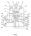
- les figures 3, 4 et 5 représentent schématiquement trois configurations de fonctionnement du dispositif montré à la figure 2. Sur ces figures ont été supprimés, par simplification, la plupart des éléments mécaniques ainsi que les distributeurs, seul le circuit hydraulique résultant de la position de chaque distributeur étant figuré. Ainsi,
- la figure 3 représente le dispositif lorsque les- deux moteurs-pompes sont moteurs et qu'il n'y a donc pas de transfert direct de puissance d'un côté sur l'autre du véhicule ;
- la figure 4 représente la configuration où un des moteurs-pompes de chaque transmission de translation fonctionne en pompe, l'autre moteur-pompe étant en fonctionnement moteur ;
- la figure 5 représente le dispositif lorsque chacun des moteurs-pompes est en fonctionnement moteur ;
- la figure 6 représente un troisième mode de réalisation de l'invention dans lequel chaque transmission de translation comporte un premier moteur et deux moteurs-pompes situés du côté du véhicule opposé au premier moteur et dont un seul des deux moteurs-pompes peut être mis en parallèle sur le premier moteur de chaque transmission de translation au moyen d'un distributeur.
- FIG. 1 represents a first embodiment in which each translation transmission comprises only a first motor-pump motor,
- FIG. 2 represents a second embodiment in which each translation transmission has two motor pumps, each of which can be coupled in the hydraulic circuit on the first motor of one or other of the translation transmissions,
- Figures 3, 4 and 5 schematically represent three operating configurations of the device shown in Figure 2. In these figures have been removed, for simplicity, most of the mechanical elements as well as the distributors, only the hydraulic circuit resulting from the position of each distributor being figured. So,
- FIG. 3 represents the device when the two pump-motors are motors and there is therefore no direct transfer of power from one side to the other of the vehicle;
- FIG. 4 represents the configuration where one of the motor-pumps of each translation transmission operates as a pump, the other motor-pump being in motor operation;
- FIG. 5 represents the device when each of the pump-motors is in motor operation;
- FIG. 6 represents a third embodiment of the invention in which each translation transmission comprises a first motor and two motor pumps situated on the side of the vehicle opposite to the first motor and of which only one of the two motor motors can be parallel on the first motor of each translation transmission by means of a distributor.
Le dispositif représenté à la figure 1, selon le premier mode de réalisation comprend donc deux transmissions hydrostatiques de translation entraînées par un moteur thermique 1 au moyen d'un train d'engrenages 2, 2a, 2b. Les arbres de sortie des engrenages 2a et 2b commandent respectivement la rotation de deux pompes à cylindrée variable 3a et 3b.The device shown in Figure 1, according to the first embodiment therefore comprises two hydrostatic translation transmissions driven by a heat engine 1 by means of a
La pompe 3a (respectivement 3b) alimente en fluide un premier moteur 4a (respectivement 4b) et en parallèle hydrauliquement sur celui-ci un second moteur 5a (respectivement 5b). Le second moteur de chaque transmission est situé sur le véhicule du côté opposé à la transmission à laquelle il appartient et il est relié mécaniquement au premier moteur de la transmission opposée. Ainsi sur la figure 1, la transmission (pompe 3a, premier moteur 4a) située sur le côté gauche du véhicule (non représenté) voit son second moteur 5a situé sur le côté droit du véhicule et lié par un réducteur mécanique 6b au premier moteur 4b de la transmission de droite (pompe 3b, premier moteur 4b et second moteur 5b). De même le second moteur 5b de la deuxième transmission de translation est lié par un réducteur mécanique 6a au premier moteur 4a.The
Le circuit hydraulique alimentant le moteur-pompe de chaque transmission comprend un distributeur (respectivement 7a et 7b) à deux positions, du type linéaire ou rotatif.The hydraulic circuit supplying the motor-pump of each transmission comprises a distributor (respectively 7a and 7b) with two positions, of the linear or rotary type.
Le moteur-pompe à cylindrée variable est par exemple du type à pistons axiaux, auquel cas la variation de cylindrée peut être obtenue par la modification de l'inclinaison du plateau sur lequel s'appuient les pistons. Lorsque, par ce moyen, la cylindrée du moteur-pompe d'une des transmissions s'annule, un dispositif de commande autorise le changement de position du distributeur de ladite transmission.The variable displacement pump motor is by example of the axial piston type, in which case the variation in displacement can be obtained by modifying the inclination of the plate on which the pistons are supported. When, by this means, the displacement of the pump motor of one of the transmissions is canceled, a control device authorizes the change of position of the distributor of said transmission.
Ainsi le distributeur 7a est commandé par le passage à zéro (ou au voisinage de zéro) de la cylindrée du moteur-pompe 5a tandis que le distributeur 7b est commandé par le moteur-pompe 5b.Thus the
Le passage à la deuxième position du distributeur (non représentée sur la figure 1) est obtenu lorsque le moteur-pompe correspondant passe d'un fonctionnement pompe au fonctionnement moteur. Le moteur-pompe 5a devenu moteur est alors relié hydrauliquement en parallèle sur le premier moteur 4b de la seconde transmission (3b, 4b) auquel il est relié mécaniquement par ailleurs au moyen du réducteur 6b. Il en est alors de même pour les moteurs 4a et 5b. On voit donc que, les valeurs de cylindrée des moteurs-pompes 5a et 5b étant identiques en translation, le passage d'une position à l'autre des deux distributeurs 7a et 7b se fera au même instant.The transition to the second position of the distributor (not shown in FIG. 1) is obtained when the corresponding motor-pump changes from pump operation to motor operation. The motor-pump 5a which has become a motor is then hydraulically connected in parallel to the
Le dispositif est complété par une pompe de direction 8 entraînée par le moteur 1 au moyen de la boîte de répartition contenant l'engrenage 2 et elle est reliée hydrauliquement aux branches haute pression de chacune des transmissions de translation. La pompe 8 est équipée d'un distributeur 9 à deux positions permettant l'inversion de sens de fluide pour exercer la fonction direction en marche arrière.The device is completed by a
Au démarrage du véhicule, en ligne droite, les moteurs-pompes Sa et 5b sont à cylindrée maxi- mate et fonctionnent en moteur. Les distributeurs 7a et 7b sont dans leur seconde position (non montrées sur la figure 1) et la pompe 3a (respectivement 3b) alimente les moteurs 4a et 5b (respectivement 4b et 5a).When the vehicle starts, in a straight line, the pump motors Sa and 5b are of maximum displacement and operate as an engine. The
Dans cette phase de fonctionnement, il n'y a donc pas transfert de la puissance d'un côté sur l'autre et le couple de giration est maximal. Une régulation tachymétrique de la cylindrée des pompes 3a et 3b et des moteurs-pompes 5a et 5b liée directement ou indirectement à l'augmentation de la vitesse de la génération de puissance permet l'augmentation de la vitesse du véhicule. Au moyen de cette régulation, on fait décroître la cylindrée des moteurs-pompes 5a et 5b jusqu'à l'annuler. Dès lors ils fonctionnent en pompe et les distributeurs 7a et 7b reprennent la position montrée sur la figure 1. On se trouve alors dans une phase où les pompes 3a et 5a (respectivement 3b et 5b) débitent en parallèle dans le moteur 4a (respectivement 4b) en passant, en ce qui concerne les pompes 5a et 5b de la cylindrée nulle à la cylindrée maximale nécessaire à l'obtention de la vitesse désirée.In this operating phase, there is therefore no transfer of power from one side to the other and the torque is maximum. Tachometric regulation of the displacement of the
En virage, aux faibles vitesses d'avancement du véhicule, lorsqu'en ligne droite les moteurs-pompes Sa et 5b fonctionnent en moteur, il n'y a pas de recyclage de puissance directement d'une chenille à l'autre. Le recyclage s'effectuera uniquement par les pompes principales 3a et 3b par l'intermédiaire de la boîte de répartition (2a, 2, 2b).When cornering, at low vehicle forward speeds, when the Sa and 5b pump motors are operating in a straight line, there is no power recycling directly from one track to another. Recycling will only be carried out by the
Aux vitesses d'avancement plus élevées, lorsque en ligne droite les moteurs-pompes 5a et 5b fonctionnent en pompe, et dans le cas par exemple d'un virage à gauche, le moteur 4a est entraîné par le barbotin gauche devenu menant. Il fonctionne alors en pompe et alimente les pompes 3a et 5a devenues moteurs. La pompe 3a devenue moteur entraîne mécaniquement par l'intermédiaire de la boîte de répartition les pompes 3b et 8 qui alimentent le moteur 4b. La pompe 5b alimente également le moteur 4b.At higher forward speeds, when in a straight line the
Il apparaît donc un recyclage de la puissance par deux voies différentes :
- - une voie indirecte de
4a vers 4b par l'intermédiaire des éléments 3a, 2a, 2, 2b, 8et 3b ; - - une voie directe de 4a vers 5a et de
5b vers 4b.
- - an indirect route from 4a to 4b via
elements - - a direct route from 4a to 5a and from 5b to 4b.
Il est à noter que la génération de puissance fournit en virage un complément d'énergie au barbotin extérieur.It should be noted that the power generation provides additional energy to the outside sprocket when cornering.
L'effort disponible sur le barbotin extérieur croît alors de son minimum pour la cylindrée nulle des moteurs-pompes jusqu'à une valeur maximale pour la cylindrée maximale des moteurs-pompes.The force available on the external gypsy then increases from its minimum for the zero displacement of the pump motors to a maximum value for the maximum displacement of the pump motors.
La pompe de direction permet de transmettre partiellement ou en totalité la puissance non utilisée de la génération de puissance et de maintenir la vitesse initiale en apportant un complément de débit aux récepteurs extérieurs. En effet, elle aspire alors du fluide dans la boucle haute pression devenue en virage boucle basse pression du côté intérieur au virage, pour le refouler sur la boucle haute pression vers le récepteur situé du côté extérieur au virage.The steering pump makes it possible to partially or entirely transmit the unused power of the power generation and to maintain the initial speed by providing additional flow to the external receivers. Indeed, it then sucks fluid into the high pressure loop which has become a low pressure loop turn on the inside of the turn, to discharge it on the high pressure loop to the receiver located on the outside of the turn.
Ce premier mode de réalisation de l'invention présente la caractéristique d'un couple de gira- tion maximal à l'arrêt du véhicule pour tourner sur place ou au démarrage du véhicule, qui décroît ensuite jusqu'à la vitesse correspondant au point où les moteurs-pompes sont à cylindrée nulle pour croître à nouveau jusqu'à un maximum puis, compte tenu de l'effort important nécessaire à la translation à vitesse élevée, redécroître très faiblement jusqu'à la vitesse maximale du véhicule en ligne droite.This first embodiment of the invention has the characteristic of a torque gira - Maximum tion to the judgment of the vehicle to turn in place or the vehicle is started, which then decreases until the speed corresponding to the point where motor-pumps are of zero displacement to increase again to a maximum then, taking into account the significant effort necessary for the translation at high speed, to decrease very slightly until the maximum speed of the vehicle in a straight line.
Dans le second mode de réalisation, montré à la figure 2, et qui représente une variante de réalisation du premier type de la figure 1, on a remplacé le moteur-pompe unique de chaque transmission de translation par deux moteurs-pompes 50a et 51 a (respectivement 50b et 51 b) identiques. Ce mode de réalisation a pour avantage de permettre un déphasage des variations des cylindrées des deux moteurs-pompes qui rend possible l'augmentation de la valeur minimale du couple de giration et l'obtention de celle-ci.In the second embodiment, shown in FIG. 2, and which represents an alternative embodiment of the first type in FIG. 1, the single pump motor of each translation transmission has been replaced by two
Ce mode de réalisation diffère de la première réalisation décrite en ce qu'il comporte, pour chaque transmission de translation, en sus des deux moteurs-pompes 50a et 51 (respectivement 50b et 51 b), deux distributeurs 7a et 70a (respectivement 7b et 70b) dont le changement de position est commandé par le passage à cylindrée nulle des moteurs-pompes respectifs précités. De plus, les deux moteurs-pompes de chaque transmission sont reliés entre eux et liés au premier moteur de la transmission opposée par un moyen mécanique constitué par un train d'engrenages 10a, 11 a, 12a (respectivement 10b, 11 b, 12b).This embodiment differs from the first embodiment described in that it comprises, for each translational transmission, in addition to the two pump-
De la même façon que dans le premier mode de réalisation, on utilise des régulations tachymétriques pour commander les cylindrées des moteurs-pompes hydrauliques 50a, 50b, 51 a et 51 b à partir de leur vitesse d'entraînement de façon à conserver en virage les mêmes cylindrées, évitant la chute de vitesse du véhicule qu'entraînerait l'augmentation de la cylindrée des moteurs-pompes liés à une régulation par pression.In the same way as in the first embodiment, tachometric regulations are used to control the displacements of the hydraulic motor-
Dans la suite du texte pour la commodité de l'explication, on utilisera les références des organes sans leurs indices littéraux lorsque le fonctionnement décrit sera valable sur un côté ou sur l'autre du véhicule. Ainsi « le moteur-pompe 50 côté intérieur » signifiera le moteur-pompe 50a si le virage est effectué à droite ou le moteur-pompe 50b si le virage est effectué à gauche.In the following text for the convenience of the explanation, the references of the members will be used without their literal indices when the operation described is valid on one side or the other of the vehicle. Thus “the motor-
En ce qui concerne le fonctionnement, deux cas sont à considérer :
- - aux basses vitesses, les moteurs-pompes 50 et 51 sont moteurs en ligne droite ; en virage, ils deviennent pompes en ce qui concerne le côté intérieur alors qu'ils restent moteurs sur le côté extérieur ;
- - aux hautes vitesses, les moteurs-pompes 50 et 51 sont en fonctionnement pompe ; en virage, ceux situés du côté intérieur restent pompes tandis que les moteurs-pompes côté extérieur deviennent moteurs. Les moteurs-pompes 50 et 51 intérieures au virage alimentent partiellement le moteur 4 côté extérieur tandis que la pompe 3 du côté intérieur au virage est devenue moteur ; le moteur 4 intérieur devenu pompe alimente partiellement les moteurs-pompes 50 et 51 extérieurs ainsi que la pompe 3 intérieure devenue moteur en virage. Il y a donc un transfert de puissance direct par les pompes 3
et 8 et les moteurs-pompes 50 et 51 et un transfert direct d'un barbotin à l'autre des moteurs-pompes 50 et 51 intérieurs au moteur 4 extérieur et du moteur 4 intérieur aux moteurs-pompes 50 et 51 extérieurs.
- - at low speeds, the
pump motors 50 and 51 are motors in a straight line; when cornering, they become pumps as regards the interior side while they remain engines on the exterior side; - - At high speeds, the
pump motors 50 and 51 are in pump operation; when cornering, those located on the inside remain pumps while the motor-pumps on the outside become motors. Thepump motors 50 and 51 inside the bend partially supply the motor 4 on the outside side while thepump 3 on the inside of the bend has become an engine; the interior motor 4 which has become a pump partially supplies the external motor-pumps 50 and 51 as well as theinterior pump 3 which has become a cornering motor. There is therefore a direct transfer of power by thepumps pump motors 50 and 51 and a direct transfer from one gypsy to the other from thepump motors 50 and 51 inside to the engine 4 outside and from the engine 4 inside thepump motors 50 and 51 outside.
L'organisation et les régulations des transmissions adoptées conduisent à considérer les trois phases de fonctionnement en virage :
- - A basse vitesse et à couple de giration maximal, la cylindrée du premier moteur varie de sa cylindrée maximale à sa cylindrée nulle :
- - At low speed and at maximum turning torque, the displacement of the first motor varies from its maximum displacement to its zero displacement:
Les deux moteurs-pompes 50 et 51 de chaque transmission sont moteurs, il n'y a pas de transfert direct de la puissance d'une chenille à l'autre.The two motor-
En virage, les moteurs-pompes 50 et 51 du côté de la chenille extérieure restent moteurs alors que ceux du côté de la chenille intérieure deviennent pompes, les pressions s'inversent dans le circuit de la transmission du côté de la chenille intérieure ; la pompe d'alimentation 3 du côté intérieur devient moteur et transmet une partie de sa puissance à la pompe 3 de l'autre transmission (côté extérieur) ainsi qu'à la pompe de direction 8 ; le complément de la puissance est alors donné par le moteur thermique. Le schéma des transmissions est alors celui figuré à la figure 3.
- - Aux vitesses intermédiaires, le - moteur-
pompe 50 fonctionne en pompe, le moteur-pompe 51 en moteur :- Il y a transfert de la puissance directement d'une chenille à l'autre uniquement par le moteur 50.
- - At intermediate speeds, the - motor-
pump 50 operates as a pump, the motor-pump 51 as a motor:- Power is transferred directly from one track to another only by the
motor 50.
- Power is transferred directly from one track to another only by the
En virage, le moteur semi-rapide 4 et le deuxième moteur-pompe rapide 51 restent moteurs du côté extérieur, ils sont alimentés par la pompe 3 du côté extérieur ; le moteur-pompe côté extérieur qui fonctionne en pompe est relié à l'autre pompe 3 et devient moteur en virage. Le moteur semi-rapide 4 et le deuxième moteur-pompe rapide 51 du côté intérieur deviennent pompes et débitent dans la pompe d'alimentation 3 intérieure devenue moteur. Le premier moteur-pompe rapide 50 du côté intérieur relié à la pompe extérieure 3 reste pompe. On a alors un ensemble moteur sur le barbotin extérieur et un ensemble pompe sur le barbotin intérieur. Le schéma des transmissions en virage est alors celui de la figure 4.
- - Aux hautes vitesses les deux moteurs-pompes 50 et 51 fonctionnent en pompe :
- - At high speeds, the two
pump motors 50 and 51 operate as pumps:
Le transfert de la puissance directement d'une .chenille à l'autre est réalisé par les deux moteurs-pompes rapides 50 et 51.The transfer of power directly from one scale to another is carried out by the two fast motor-
En virage, les deux moteurs-pompes rapides 50 et 51 du côté extérieur, reliés au moteur du côté intérieur deviennent moteurs. Le moteur du côté extérieur reste moteur alors que celui du côté intérieur devient pompe. Les moteurs-pompes rapides 50 et 51 du côté intérieur restent pompes. Sur le côté extérieur, tous les éléments hydrauliques sont moteurs ; sur le côté intérieur, ils sont pompes. Le schéma des transmissions en virage est alors celui de la figure 5.When cornering, the two fast motor pumps 50 and 51 on the outside, connected to the engine on the inside, become engines. The motor on the outside remains motor while the one on the inside becomes pump. The fast motor-
Le troisième mode de réalisation représenté à la figure 6 constitue une variante du second mode montré à la figure 2.The third embodiment shown in FIG. 6 constitutes a variant of the second embodiment shown in FIG. 2.
Le second moteur-pompe 51 de chaque transmission de translation est couplé hydrauliquement en permanence au moteur hydraulique à cylindrée fixe 4 monté sur le barbotin opposé alors que le premier moteur-pompe 50 comporte sur son circuit le distributeur de recyclage 7 décrit précédemment qui ne permet le recyclage de la puissance que lorsque le premier moteur-pompe devient pompe.The second pump motor 51 of each translation transmission is permanently hydraulically coupled to the fixed displacement hydraulic motor 4 mounted on the opposite gypsy while the
Un tel dispositif permet alors, au cours du fonctionnement :
- - de diminuer la cylindrée des moteurs-pompes rapides 50 ayant un distributeur, jusqu'à leur cylindrée nulle.
- - à partir de ce point de fonctionnement, diminuer la cylindrée du moteur-pompe 51 jusqu'à 0 tout en augmentant la cylindrée du premier moteur-
pompe 50 qui fonctionne alors en pompe.
- - Reduce the displacement of fast motor-
pumps 50 having a distributor, until their displacement is zero. - - from this operating point, decrease the displacement of the pump motor 51 to 0 while increasing the displacement of the
first pump motor 50 which then operates as a pump.
Il est alors possible ou non de faire correspondre les points : cylindrée nulle du moteur-pompe 51 et cylindrée maximale en pompe du moteur-pompe 50.It is then possible or not to match the points: zero displacement of the pump motor 51 and maximum displacement in pump of the
On augmente enfin la cylindrée du premier moteur-pompe 50 jusqu'au point de fonctionnement maximal en pompe et éventuellement celle du second moteur pompe 51 si elle n'a pas atteint son maximum dans la deuxième phase.Finally, the capacity of the
L'avantage d'un tel dispositif réside dans le fait que l'effort disponible sur le barbotin extérieur, minimal au démarrage, augmente ainsi pendant la première phase, est à peu près constant pendant la seconde phase et croît pendant la dernière phase.The advantage of such a device lies in the fact that the effort available on the external gypsy, minimal at start-up, thus increases during the first phase, is more or less constant during the second phase and increases during the last phase.
Dans tous les types de réalisations selon l'invention précitée, on pourra avantageusement utiliser pour les pompes 3 des transmissions de translation, des régulations tachymétriques faisant varier leur cylindrée proportionnellement aux variations de vitesse de la génération de puissance de façon à leur faire débiter un débit maximal à la vitesse maximale de la génération de puissance. La superposition d'une régulation de puissance par pression (à sommation algébrique de puissance) permettra l'utilisation de ces pompes à cylindrée réduite pour des pressions élevées à leur vitesse maximale de fonctionnement et donc à la puissance maximale de la génération de puissance. Ce point de fonctionnement correspond à une utilisation du véhicule à vitesse réduite et à fort couple nécessitant une pression importante.In all types of embodiments according to the aforementioned invention, it is advantageous to use, for the
La régulation par pression à sommation algébrique de puissance permet en outre de conserver dans la phase de virage des valeurs de cylindrée importantes ce qui facilite le recyclage indirect de puissance par les pompes.Pressure regulation with algebraic power summation also makes it possible to keep large displacement values in the turning phase, which facilitates indirect recycling of power by the pumps.
La pompe de direction, à cylindrée nulle en translation, n'est pas munie de régulations mais la valeur de sa cylindrée sera commandée directement par l'opérateur pour accomplir les fonctions de virage.The steering pump, with zero displacement in translation, is not provided with regulations but the value of its displacement will be controlled directly by the operator to perform the turning functions.
La cylindrée maximale des moteurs permet d'obtenir le couple maximal à vitesse réduite du véhicule. Simultanément à l'augmentation de la cylindrée des pompes 3 il conviendra de réduire la cylindrée des éléments 50 et 51 en fonctionnement moteur jusqu'à la cylindrée nulle puis d'accroître leurs cylindrées en fonctionnement pompe jusqu'à leurs maxima, ceux-ci étant atteints simultanément aux maxima des cylindrées des pompes 3. Cette variation conjointe de cylindrée des divers éléments permettra le passage par variation continue de la vitesse minimale du véhicule à sa vitesse maximale et de son couple maximal à son couple minimal. Ces variations seront commandées par des régulations tachymétriques, soit à partir de la vitesse de rotation de la génération de puissance, soit de façon préférentielle à partir de la vitesse des barbotins du véhicule.The maximum engine displacement makes it possible to obtain the maximum torque at reduced speed of the vehicle. Simultaneously with the increase in the displacement of the
L'invention dans chacun de ses modes de réalisation présente pour autre avantage le fait qu'en virage, le transfert de la puissance par voies hydrauliques remplace avantageusement le transfert mécanique en réduisant la .masse de l'ensemble, en simplifiant l'implantation des composants et en protégeant le dispositif des pointes éventuelles de couple, par l'existence des soupapes montées de façon connue sur les circuits des transmissions hydrostatiques.The invention in each of its embodiments has the other advantage that in turns, the transfer of power by hydraulic means advantageously replaces mechanical transfer by reducing the mass of the assembly, by simplifying the installation of components and protecting the device from possible torque peaks, by the existence of valves mounted in a known manner on the hydrostatic transmission circuits.
En outre, l'ensemble des dispositifs, transmissions de translation avec transfert de puissance hydraulique direct et pompe de direction, objet de l'invention, permet de bénéficier de l'excellente mobilité et de la continuité qu'apporte la transmission hydrostatique tant en ligne droite qu'en virage. En outre, il permet les couples de giration nécessaires au bon comportement en virage en fonction de la vitesse d'avancement du véhicule et le maintien de cette vitesse en virage.In addition, all of the devices, translation transmissions with direct hydraulic power transfer and steering pump, object of the invention, makes it possible to benefit from the excellent mobility and continuity provided by hydrostatic transmission both online. right than in turns. In addition, it allows the torques required for good cornering behavior as a function of the forward speed of the vehicle and maintaining this speed when cornering.
L'invention s'applique donc avec intérêt aux véhicules tels que les engins de travaux publics, ou les chars de combat pour lesquels on souhaite obtenir une grande mobilité tant en ligne droite qu'en virage sans augmentation excessive de la masse du véhicule.The invention therefore applies with interest to vehicles such as public works vehicles, or combat tanks for which it is desired to obtain high mobility both in a straight line and in turns without excessive increase in the mass of the vehicle.
Claims (10)
Applications Claiming Priority (2)
| Application Number | Priority Date | Filing Date | Title |
|---|---|---|---|
| FR7922518 | 1979-09-10 | ||
| FR7922518A FR2464869A1 (en) | 1979-09-10 | 1979-09-10 | HYDROSTATIC TRANSMISSION PROPELLER GROUP FOR TRANSLATION AND STEERING WITH HYDRAULIC RECYCLING OF CURRENT POWER |
Publications (2)
| Publication Number | Publication Date |
|---|---|
| EP0025372A1 EP0025372A1 (en) | 1981-03-18 |
| EP0025372B1 true EP0025372B1 (en) | 1983-06-01 |
Family
ID=9229488
Family Applications (1)
| Application Number | Title | Priority Date | Filing Date |
|---|---|---|---|
| EP80401161A Expired EP0025372B1 (en) | 1979-09-10 | 1980-08-07 | Hydrostatic-transmission propulsion unit for translation and power regenerative steering |
Country Status (3)
| Country | Link |
|---|---|
| EP (1) | EP0025372B1 (en) |
| DE (1) | DE3063612D1 (en) |
| FR (1) | FR2464869A1 (en) |
Families Citing this family (8)
| Publication number | Priority date | Publication date | Assignee | Title |
|---|---|---|---|---|
| GB2246844A (en) * | 1990-07-13 | 1992-02-12 | Glowreach Limited | Vehicle with auxiliary drive system |
| FR2705639B1 (en) * | 1993-05-24 | 1995-07-21 | France Etat Armement | Vehicle with hydrostatic transmission and steering by steered wheels and skid. |
| DE19833942C2 (en) | 1998-07-28 | 2000-06-08 | Brueninghaus Hydromatik Gmbh | Hydrostatic drive with differential lock |
| DE10128589C1 (en) | 2001-06-13 | 2003-07-03 | Brueninghaus Hydromatik Gmbh | Hydrostatic drive |
| DE10356155B4 (en) * | 2003-12-02 | 2006-06-14 | Brueninghaus Hydromatik Gmbh | Hydrostatic drive system with pump-side hydraulic fluid volume division |
| DE102004061557B4 (en) * | 2004-12-21 | 2006-12-14 | Brueninghaus Hydromatik Gmbh | Hydrostatic drive with differential locking effect |
| DE102011105440A1 (en) * | 2011-06-24 | 2012-12-27 | Robert Bosch Gmbh | Hydrostatic drive |
| EP3378736B1 (en) * | 2017-03-20 | 2020-04-29 | Repaircraft PLC | Drive system for tracked vehicles and tracked working machines and method for controlling a drive system for tracked vehicles and tracked working machines |
Citations (1)
| Publication number | Priority date | Publication date | Assignee | Title |
|---|---|---|---|---|
| FR2445258A1 (en) * | 1978-12-26 | 1980-07-25 | France Etat | HYDRAULIC PROPELLER FOR VEHICLE, WITH MECHANICAL RECYCLING OF TURNED POWER |
Family Cites Families (13)
| Publication number | Priority date | Publication date | Assignee | Title |
|---|---|---|---|---|
| DE957184C (en) * | 1952-08-22 | 1957-01-31 | Hydromatic G M B H | Tracked vehicle drive |
| US3081647A (en) * | 1957-02-27 | 1963-03-19 | Fairchild Stratos Corp | Regenerative steering |
| GB863560A (en) * | 1958-10-08 | 1961-03-22 | Brown David Ind Ltd | New or improved power transmission means for vehicles |
| US3368425A (en) * | 1965-05-27 | 1968-02-13 | Gen Electric | Steering and driving power system |
| US3575066A (en) * | 1969-09-23 | 1971-04-13 | Gen Motors Corp | Transmission |
| US3744584A (en) * | 1971-04-29 | 1973-07-10 | Int Harvester Co | Hydrostatic transmission motors and coordinating clutch for same |
| US3774401A (en) * | 1972-06-26 | 1973-11-27 | Cmi Corp | Automatic control system for use with a hydraulic drive system |
| US3862668A (en) * | 1973-06-13 | 1975-01-28 | Eaton Corp | Hydrostatic transmission control system |
| DE2446727A1 (en) * | 1974-09-30 | 1976-04-15 | Serck Industries Ltd | Steering system for endless chain driven vehicles - has hydraulically braked or driven epicyclic gear steering trim unit |
| US4019596A (en) * | 1975-12-30 | 1977-04-26 | Sundstrand Corporation | Synchronous control system |
| US4024710A (en) * | 1976-03-25 | 1977-05-24 | Koehring Company | Load sensing hydraulic circuit having power matching means |
| US4086767A (en) * | 1977-01-24 | 1978-05-02 | Commercial Shearing, Inc. | Track drive circuits with synchronization and steering systems |
| GB1559225A (en) * | 1977-02-02 | 1980-01-16 | Caterpillar Tractor Co | Hydrostatic transmission with differential steering |
-
1979
- 1979-09-10 FR FR7922518A patent/FR2464869A1/en active Granted
-
1980
- 1980-08-07 EP EP80401161A patent/EP0025372B1/en not_active Expired
- 1980-08-07 DE DE8080401161T patent/DE3063612D1/en not_active Expired
Patent Citations (1)
| Publication number | Priority date | Publication date | Assignee | Title |
|---|---|---|---|---|
| FR2445258A1 (en) * | 1978-12-26 | 1980-07-25 | France Etat | HYDRAULIC PROPELLER FOR VEHICLE, WITH MECHANICAL RECYCLING OF TURNED POWER |
Also Published As
| Publication number | Publication date |
|---|---|
| FR2464869B1 (en) | 1984-01-06 |
| DE3063612D1 (en) | 1983-07-07 |
| FR2464869A1 (en) | 1981-03-20 |
| EP0025372A1 (en) | 1981-03-18 |
Similar Documents
| Publication | Publication Date | Title |
|---|---|---|
| EP1934471B1 (en) | Device for managing the displacement of a hydraulic motor or a group of hydraulic motors | |
| EP2981426B1 (en) | Hydraulic transmission device | |
| FR3001774A1 (en) | HYDRAULIC PUMP MOTOR WITH FIXED OR VARIABLE CYLINDREE | |
| EP0993982A1 (en) | Auxilliary drive device for vehicle with mechanical main drive | |
| EP0025372B1 (en) | Hydrostatic-transmission propulsion unit for translation and power regenerative steering | |
| FR2629171A1 (en) | HYDROSTATIC TRANSMISSION DEVICE AND APPLICATION TO MOTOR POWERTRAIN OR MOTOR VEHICLE | |
| WO2012131218A1 (en) | Vehicle comprising a hybrid combustion engine/hydraulic power train with power distribution | |
| FR2970908A1 (en) | Kinematic traction chain for hybrid motor vehicle, has engaging or disengaging units to engage or disengage mechanical connection between engine and wheels, where gear ratios of units are adopted for obtaining optimized output at high speed | |
| EP0026115B1 (en) | Hydrostatic transmissions with a wide working range | |
| EP2817164B1 (en) | Compact hydraulic module for hydraulic hybrid vehicle | |
| EP2376769B1 (en) | Hydraulic transmission circuit | |
| EP0013190B2 (en) | Hydraulic drive unit for a vehicle having a power splitting mechanism for steering | |
| EP2817167B1 (en) | Compact hydraulic module for hydraulic hybrid vehicle | |
| FR2697883A1 (en) | Hydromechanical drive assembly. | |
| WO2015189324A1 (en) | Method for activating a hydraulic assistance of a vehicle transmission system | |
| EP2817165B1 (en) | Compact hydraulic module for hydraulic hybrid vehicle | |
| BE1007042A3 (en) | RECOVERY STEERING CONTROL SYSTEM FOR HYDROSTATIC DRIVES. | |
| FR2705639A1 (en) | Vehicle with hydrostatic transmission and steering by steered wheels and skid. | |
| EP3824205B1 (en) | Hydraulic assistance circuit comprising improved feeding means | |
| EP2643584A1 (en) | Variable displacement hydraulic machine, in particular for a motor vehicle | |
| WO2015132488A1 (en) | Hydraulic module incorporated into a transmission for a hydraulically powered motor vehicle | |
| EP2817166B1 (en) | Compact hydraulic module for hydraulic hybrid vehicle | |
| WO2014087019A1 (en) | Hydrostatic transmission of a vehicle with motor engagement according to the optimum ranges of operation thereof | |
| WO2017098097A1 (en) | Four-wheel drive motor vehicle with hybrid propulsion comprising a differential provided with a hydraulic module | |
| WO2011104383A1 (en) | Device for propelling a vehicle with energy recovery and restitution |
Legal Events
| Date | Code | Title | Description |
|---|---|---|---|
| PUAI | Public reference made under article 153(3) epc to a published international application that has entered the european phase |
Free format text: ORIGINAL CODE: 0009012 |
|
| AK | Designated contracting states |
Designated state(s): CH DE GB SE |
|
| 17P | Request for examination filed |
Effective date: 19810407 |
|
| GRAA | (expected) grant |
Free format text: ORIGINAL CODE: 0009210 |
|
| AK | Designated contracting states |
Designated state(s): CH DE GB LI SE |
|
| REF | Corresponds to: |
Ref document number: 3063612 Country of ref document: DE Date of ref document: 19830707 |
|
| PLBE | No opposition filed within time limit |
Free format text: ORIGINAL CODE: 0009261 |
|
| STAA | Information on the status of an ep patent application or granted ep patent |
Free format text: STATUS: NO OPPOSITION FILED WITHIN TIME LIMIT |
|
| 26N | No opposition filed | ||
| EAL | Se: european patent in force in sweden |
Ref document number: 80401161.7 |
|
| PGFP | Annual fee paid to national office [announced via postgrant information from national office to epo] |
Ref country code: SE Payment date: 19990716 Year of fee payment: 20 |
|
| PGFP | Annual fee paid to national office [announced via postgrant information from national office to epo] |
Ref country code: GB Payment date: 19990727 Year of fee payment: 20 |
|
| PGFP | Annual fee paid to national office [announced via postgrant information from national office to epo] |
Ref country code: CH Payment date: 19990928 Year of fee payment: 20 |
|
| PGFP | Annual fee paid to national office [announced via postgrant information from national office to epo] |
Ref country code: DE Payment date: 19991022 Year of fee payment: 20 |
|
| PG25 | Lapsed in a contracting state [announced via postgrant information from national office to epo] |
Ref country code: LI Free format text: LAPSE BECAUSE OF EXPIRATION OF PROTECTION Effective date: 20000806 Ref country code: GB Free format text: LAPSE BECAUSE OF EXPIRATION OF PROTECTION Effective date: 20000806 Ref country code: CH Free format text: LAPSE BECAUSE OF EXPIRATION OF PROTECTION Effective date: 20000806 |
|
| PG25 | Lapsed in a contracting state [announced via postgrant information from national office to epo] |
Ref country code: SE Free format text: THE PATENT HAS BEEN ANNULLED BY A DECISION OF A NATIONAL AUTHORITY Effective date: 20000808 |
|
| REG | Reference to a national code |
Ref country code: GB Ref legal event code: PE20 Effective date: 20000806 |
|
| REG | Reference to a national code |
Ref country code: CH Ref legal event code: PL |
|
| EUG | Se: european patent has lapsed |
Ref document number: 80401161.7 |