EP0025149B2 - Apparat zum Messen des Durchflusses von Gas - Google Patents
Apparat zum Messen des Durchflusses von Gas Download PDFInfo
- Publication number
- EP0025149B2 EP0025149B2 EP80104949A EP80104949A EP0025149B2 EP 0025149 B2 EP0025149 B2 EP 0025149B2 EP 80104949 A EP80104949 A EP 80104949A EP 80104949 A EP80104949 A EP 80104949A EP 0025149 B2 EP0025149 B2 EP 0025149B2
- Authority
- EP
- European Patent Office
- Prior art keywords
- opening
- supply path
- gas
- main supply
- bypass
- Prior art date
- Legal status (The legal status is an assumption and is not a legal conclusion. Google has not performed a legal analysis and makes no representation as to the accuracy of the status listed.)
- Expired
Links
- 125000006850 spacer group Chemical group 0.000 claims description 16
- 238000011144 upstream manufacturing Methods 0.000 claims description 6
- 238000005259 measurement Methods 0.000 description 3
- 229920003002 synthetic resin Polymers 0.000 description 3
- 239000000057 synthetic resin Substances 0.000 description 3
- 238000002485 combustion reaction Methods 0.000 description 2
- 238000010276 construction Methods 0.000 description 2
- 239000000446 fuel Substances 0.000 description 2
- 238000002347 injection Methods 0.000 description 2
- 239000007924 injection Substances 0.000 description 2
- BASFCYQUMIYNBI-UHFFFAOYSA-N platinum Chemical compound [Pt] BASFCYQUMIYNBI-UHFFFAOYSA-N 0.000 description 2
- 230000015556 catabolic process Effects 0.000 description 1
- 238000006731 degradation reaction Methods 0.000 description 1
- 238000001514 detection method Methods 0.000 description 1
- 239000000945 filler Substances 0.000 description 1
- 238000009434 installation Methods 0.000 description 1
- 239000011810 insulating material Substances 0.000 description 1
- 238000004519 manufacturing process Methods 0.000 description 1
- 230000035945 sensitivity Effects 0.000 description 1
- 230000006641 stabilisation Effects 0.000 description 1
- 238000011105 stabilization Methods 0.000 description 1
Images
Classifications
-
- G—PHYSICS
- G01—MEASURING; TESTING
- G01F—MEASURING VOLUME, VOLUME FLOW, MASS FLOW OR LIQUID LEVEL; METERING BY VOLUME
- G01F1/00—Measuring the volume flow or mass flow of fluid or fluent solid material wherein the fluid passes through a meter in a continuous flow
- G01F1/68—Measuring the volume flow or mass flow of fluid or fluent solid material wherein the fluid passes through a meter in a continuous flow by using thermal effects
- G01F1/684—Structural arrangements; Mounting of elements, e.g. in relation to fluid flow
- G01F1/6842—Structural arrangements; Mounting of elements, e.g. in relation to fluid flow with means for influencing the fluid flow
-
- G—PHYSICS
- G01—MEASURING; TESTING
- G01F—MEASURING VOLUME, VOLUME FLOW, MASS FLOW OR LIQUID LEVEL; METERING BY VOLUME
- G01F5/00—Measuring a proportion of the volume flow
Definitions
- the present invention relates to a flow measuring device and, more particularly, to an apparatus for measuring the flow rate of a gas.
- An air flow measuring apparatus having a heat generating resistance body such as a platinum wire mounted in a path of air flow by means of an attachment is known from the specification of United States Patent No. 3824966 issued to Schneider at al on July 23, 1974.
- This air flow measuring apparatus suffers, when used as an air flow measuring apparatus for measuring the intake air flow rate in an internal combustion engine, that the wire is burnt out or deteriorated due to the reverse flow of gas in the event of a back fire and, accordingly, has a poor durability.
- the adjustment of the tension of the wire is extremely difficult. Namely, if the tension is excessively large, the wire becomes more liable to be broken. To the contrary, a too low tension inconveniently permits the wire to be vibrated to cause a degradation of the precision of measurement.
- the United States Patent No. 3559482 granted on Baker et al of February 2, 1971 proposes to dispose an air flowing measuring apparatus in a bypass passage between an opening disposed at a portion of the air intake passage downstream from a venturi and an opening formed at a portion of the same upstream from the venturi.
- This air flow measuring apparatus is superior in that it can shelter from the reversing flow of gas in the event of back fire and that the installation of the air flow measuring apparatus is comparatively easy.
- the size of the apparatus can be made considerably small.
- the US-A 3683692 proposes to dispose an air flow measuring apparatus in a bypass member between an opening disposed at a portion of the air intake passage downstream from a plate having a certain number of calibrated perforations and an opening disposed at a portion of the air intake passage upstream from said plate which is mounted in the main supply path perpendicularly to the gas flow direction.
- a spacer is interposed between the main supply path and the bypass member and is provided with an opening communicating with a narrow groove in said bypass member which groove communicates with a cylindrical cavity in the central part of the bypass member with cavity contains a sensing element.
- the gas flow passage through the bypass member is rather complicated.
- DE-A 2653359 discloses an apparatus for measuring the flow rate of a gas, comprising a main supply path having two openings formed in the wall thereof and connected to each other by a bypass air passage wherein a pair of resistance members is disposed, the main supply path containing a venturi member having its narrowest section at the second opening as seen in the flow direction.
- an object of the invention to provide an air flow measuring apparatus easily adjustable for different measuring characteristics and, hence, suitable for a mass-production.
- an apparatus for measuring the flow rate of a gas comprising: a main supply path through which said gas flows, said main supply path having a first and a second opening formed in the wall thereof and spaced by a predetermined distance in the direction of flow of said gas; a bypass member detachably fixed to the outside of said main supply path and provided with a groove being communicated at its one end with said first opening, said groove being elongate and straight; a spacer interposed between said main supply path and said bypass member and provided with an opening corresponding to said groove of said bypass member, said groove and said opening defining a bypass air passage; and a gas flow meter including a pair of resistance members disposed within said bypass member, characterized in that a venturi member is disposed in said main supply path with at least part thereof between said first and second openings and adapted to maintain a higher pressure at said first opening than at said second opening; said groove has a length greater than the distance between said first and second openings and communicates at its other end with
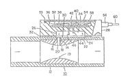
- an intake barrel 10 is a stepped cylindrical member the inside diameter of which is greater at the upstream side than at the downstream side thereof.
- a venturi member 12 is inserted into the intake barrel from the upstream side end of the latter, and is fixed to the inside of the intake barrel 10 by means of a pipe 18 whih is driven into an opening 14 formed at the outside of the central portion of the venturi member 12 and an opening 16 formed in the wall of the intake barrel 10 at a portion of the latter confronting the opening 14.
- An opening 20 is formed at the narrowest throat portion 19 of the venturi member 12 so as to communicate with the pipe 18.
- An opening 22 is formed in the wall of the intake barrel 10 at a portion of the latter upstream from the venturi member 12.
- the opening 22 and the opening 20 in the venturi member 12 are located on a line parallel to the central axis of the intake barrel 10.
- the opening 22 is provided with a filter 24.
- a bypass passage forming member 28 made of a synthetic resin and provided with a rectangular groove 26 of a length greater than the distance between the openings 20, 22 is fixed to the outside of the intake barrel 10.
- a spacer 32 made of a synthetic resin is placed between the bypass passage forming member 28 and the intake barrel 10. The spacer 32 is provided with a rectangular bore of a size equal to that of the groove 26.
- the openings 22 and 20 are communicated with each other to form a bypass passage 34.
- a circuit board 38 is accommodated by a recess 36 formed in the bypass passage forming member 28 so as to oppose to the groove 26.
- Two sets of support pins 40, 42 extending through the central portion of the bypass passage forming member 28 are connected at their one ends to the electronic parts of the circuit board 38, while the other ends of the same are connected to a flow rate sensor 44 and a temperature compensation sensor 46.
- the flow rate sensor 44 is a resistance member whose resistance value is varied at a high sensitivity in response to a change in the flow rate
- the temperature compensation sensor 46 is a resistance member whose resistance value depends on the air temperature irrespective of the air flow rate.
- the flow rate sensor 44 and the temperature compensation sensor 46 are connected to two sides of a bridge circuit formed on the circuit board 38.
- the circuit board 38 is coated with an antihu- midity insulating material 52 so that the electric insulating performance thereof is much improved.
- the recess 36 is filled with an insulating filler 54 and is then sealed by means of a cover 55.
- a connector 56 provided at the outside of the bypass forming passage 28 is connected to a terminal 58 so as to supply the bridge circuit on the circuit board 38 with the required electric power.
- an air flow meter is formed on the bypass passage forming member 28 by means of the flow rate sensor 44, temperature compensation sensor 46 and the circuit board including the bridge circuit.
- the level of vacuum generated around the opening 20 of the venturi member 12 is changed in accordance with the change of flow rate of air passing the intake barrel 10. Accordingly, the velocity of air flowing through the bypass air passage 34 is changed.
- the change of the velocity of air is detected by the flow rate sensor 44 and the temperature compensation sensor 46 which are connected in a bridge, and an electric output corresponding to the flow rate of air flowing through the intake barrel 10 is derived from the output terminal 60.
- This principle of operation is disclosed, in, for example, the specification of United States Patent No. 3 824 966.
- the intake barrel 10 is communicated at its downstream side end with the combustion chamber of the engine through the throttle valve chamber and the intake pipe.
- a fuel injection valve is disposed at a portion of the throttle valve chamber downstream from the throttle valve. The operation of the fuel injection valve is controlled in relation to the output signal derived from the output terminal 60.
- the flow meter is less liable to be affected by the reversing flow of gas, even when a back fire happens to take place, partly because the openings 20, 22 of the bypass air passage 34 are sufficiently small and partly because these openings are arranged at a right angle to the intake passage, so that the erroneous measurement of the air flow rate is avoided.
- the bypass passage forming member 28 is made of a synthetic resin having a low thermal conductivity, the temperature of air flowing through the bypass passage 28 is never changed. The stabilization of the air temperature in turn suppresses the density of air to ensure a precise measurement of the air flow rate.
- the air flow measuring apparatus of the invention can apply to engines of different capacities. Namely, when the air flow measuring apparatus is applied to an engine having a larger capacity, the venturi member 12 is replaced with another venturi member having a larger cross-sectional area of passage and the spacer 32 is replaced with another spacer having a greater thickness. By so doing, the cross-sectional area to the bypass air passage 34 is increased to lower the flowing velocity of air flowing therethrough to magnify the measure- able range of the intake air flow rate.
- the intake barrel 10 and the bypass passage forming member 28 are commonly used for various capacities of engine, so that the measuring apparatus can suitably be mass-produced and the efficiency of assembling of the air flow meter is improved.
Landscapes
- Physics & Mathematics (AREA)
- Fluid Mechanics (AREA)
- General Physics & Mathematics (AREA)
- Measuring Volume Flow (AREA)
Claims (5)
Applications Claiming Priority (2)
| Application Number | Priority Date | Filing Date | Title |
|---|---|---|---|
| JP105899/79 | 1979-08-22 | ||
| JP54105899A JPS6045806B2 (ja) | 1979-08-22 | 1979-08-22 | 発熱抵抗体を用いた空気流量計 |
Publications (4)
| Publication Number | Publication Date |
|---|---|
| EP0025149A2 EP0025149A2 (de) | 1981-03-18 |
| EP0025149A3 EP0025149A3 (en) | 1983-04-13 |
| EP0025149B1 EP0025149B1 (de) | 1986-02-26 |
| EP0025149B2 true EP0025149B2 (de) | 1989-10-18 |
Family
ID=14419726
Family Applications (1)
| Application Number | Title | Priority Date | Filing Date |
|---|---|---|---|
| EP80104949A Expired EP0025149B2 (de) | 1979-08-22 | 1980-08-20 | Apparat zum Messen des Durchflusses von Gas |
Country Status (4)
| Country | Link |
|---|---|
| US (1) | US4381668A (de) |
| EP (1) | EP0025149B2 (de) |
| JP (1) | JPS6045806B2 (de) |
| DE (1) | DE3071448D1 (de) |
Families Citing this family (38)
| Publication number | Priority date | Publication date | Assignee | Title |
|---|---|---|---|---|
| DE3130626A1 (de) * | 1981-08-01 | 1983-02-17 | Robert Bosch Gmbh, 7000 Stuttgart | Vorrichtung zur messung der masse eines stroemenden mediums |
| DE3130624A1 (de) * | 1981-08-01 | 1983-02-17 | Robert Bosch Gmbh, 7000 Stuttgart | Luftmassenmessvorrichtung |
| US4418568A (en) * | 1981-09-10 | 1983-12-06 | Eaton Corporation | Hot film fluid flowmeter with auxiliary flow sensing |
| JPS58105013A (ja) * | 1981-12-18 | 1983-06-22 | Hitachi Ltd | 熱線式流量計 |
| US4509371A (en) * | 1983-01-07 | 1985-04-09 | Carrier Corporation | Venturi flow measuring device and method |
| US4571996A (en) * | 1984-08-10 | 1986-02-25 | Allied Corporation | Air flow sensor |
| GB2205947B (en) * | 1987-06-19 | 1991-09-04 | British Gas Plc | Flowmeter |
| GB8720357D0 (en) * | 1987-08-28 | 1987-10-07 | Thorn Emi Flow Measurement Ltd | Fluid metering system |
| FR2619892B1 (fr) * | 1987-08-31 | 1991-08-16 | Gaz De France | Procede pour prevenir l'encrassement d'un dispositif detecteur d'anomalies et dispositif pour l'execution de ce procede |
| US4848163A (en) * | 1987-10-30 | 1989-07-18 | Timeter Instrument Corporation | Extended range linear flow transducer |
| US4913192A (en) * | 1989-04-03 | 1990-04-03 | Unit Instruments, Inc. | Gas flow control apparatus |
| DE3916056A1 (de) * | 1989-05-17 | 1990-11-22 | Kuipers Ulrich | Messverfahren und vorrichtung zur massendurchfluss-, volumendurchfluss-, dichte- und/oder viskositaetsbestimmung und daraus abgeleiteten groessen |
| GB2253164B (en) * | 1991-02-22 | 1994-10-05 | Hoechst Uk Ltd | Improvements in or relating to electrostatic coating of substrates of medicinal products |
| GB9105699D0 (en) * | 1991-03-18 | 1991-05-01 | British Gas Plc | Supplying fluid |
| JP3182807B2 (ja) * | 1991-09-20 | 2001-07-03 | 株式会社日立製作所 | 多機能流体計測伝送装置及びそれを用いた流体量計測制御システム |
| DE69427645T2 (de) * | 1993-10-06 | 2002-05-08 | Unit Instruments, Inc. | Apparat zur handhabung von prozess fluiden |
| US6575022B1 (en) | 1995-11-25 | 2003-06-10 | Cummins Engine Company, Inc. | Engine crankcase gas blow-by sensor |
| AU1579797A (en) * | 1996-01-17 | 1997-08-11 | Micro Motion, Inc. | Bypass type coriolis effect flowmeter |
| US5804718A (en) * | 1996-04-24 | 1998-09-08 | Denso Corporation | Airflow meter having an inverted u-shape bypass passage |
| JP3783896B2 (ja) | 1997-10-13 | 2006-06-07 | 株式会社デンソー | 空気流量測定装置 |
| JP2003139593A (ja) * | 2001-11-07 | 2003-05-14 | Hitachi Ltd | 車載電子機器および熱式流量計 |
| JP4168417B2 (ja) * | 2002-11-18 | 2008-10-22 | 株式会社山武 | 流体検出装置 |
| DE10316342A1 (de) * | 2003-04-10 | 2004-10-28 | Daimlerchrysler Ag | Massenstrommessvorrichtung |
| US7228729B1 (en) | 2006-07-26 | 2007-06-12 | Lincoln Industrial Corporation | Apparatus and method for testing fuel flow |
| US8182143B2 (en) * | 2006-08-09 | 2012-05-22 | Spectrasensors, Inc. | Mobile temperature sensor |
| US7587931B2 (en) * | 2008-01-29 | 2009-09-15 | Lincoln Industrial Corporation | Apparatus and method for testing fuel flow |
| US8393228B2 (en) * | 2010-05-18 | 2013-03-12 | Mindray Medical Sweden Ab | Method and system for measuring a flow |
| DE102011115768B4 (de) | 2011-10-12 | 2014-05-08 | Hydrometer Gmbh | Gaszähler |
| EP2589821B1 (de) * | 2011-11-03 | 2017-08-02 | Heraeus Medical GmbH | Vorrichtung und Verfahren zur Erzeugung von Vakuum für Vakuumzementiersysteme |
| US9707369B2 (en) * | 2013-06-28 | 2017-07-18 | Vyaire Medical Capital Llc | Modular flow cassette |
| US9962514B2 (en) | 2013-06-28 | 2018-05-08 | Vyaire Medical Capital Llc | Ventilator flow valve |
| US9795757B2 (en) | 2013-06-28 | 2017-10-24 | Vyaire Medical Capital Llc | Fluid inlet adapter |
| US9541098B2 (en) | 2013-06-28 | 2017-01-10 | Vyaire Medical Capital Llc | Low-noise blower |
| US9746359B2 (en) | 2013-06-28 | 2017-08-29 | Vyaire Medical Capital Llc | Flow sensor |
| US9297679B2 (en) * | 2014-01-14 | 2016-03-29 | General Electric Company | Flowmeter with a flow conditioner formed by a protrusion having restriction provided upstream of the measurement section |
| JP2016090413A (ja) | 2014-11-06 | 2016-05-23 | 日立オートモティブシステムズ株式会社 | 熱式空気流量計 |
| JP6933591B2 (ja) * | 2018-02-23 | 2021-09-08 | 株式会社ミクニ | スロットル装置及び燃料蒸発ガス回収システム |
| US11112808B2 (en) * | 2019-06-28 | 2021-09-07 | The Boeing Company | Fluid flow restrictor device |
Family Cites Families (13)
| Publication number | Priority date | Publication date | Assignee | Title |
|---|---|---|---|---|
| US1827813A (en) * | 1923-09-08 | 1931-10-20 | Westinghouse Electric & Mfg Co | Flow indicator |
| GB285994A (en) * | 1926-11-25 | 1928-02-27 | John Lawrence Hodgson | Improvements in rotary gas meters |
| US1870849A (en) * | 1928-06-09 | 1932-08-09 | Hodgson John Lawrence | Flow quantity meter |
| GB514376A (en) * | 1938-02-04 | 1939-11-07 | George Thomas Huxford | Improvements in or relating to rotary fluid flow meters |
| US2243252A (en) * | 1938-02-04 | 1941-05-27 | Builders Iron Foundry | Fluid flow meter |
| US3603148A (en) * | 1968-10-18 | 1971-09-07 | Sotakazu Rikuta | Flow meter of the area type |
| US3559482A (en) * | 1968-11-27 | 1971-02-02 | Teledyne Inc | Fluid flow measuring apparatus |
| FR2085184B1 (de) * | 1970-01-08 | 1973-07-13 | Lafitte Rene | |
| US3688576A (en) * | 1970-07-24 | 1972-09-05 | Illinois Testing Laboratories | Improved air velocity measuring system and method for its calibration |
| DE2151774C3 (de) * | 1971-10-18 | 1980-04-03 | Robert Bosch Gmbh, 7000 Stuttgart | Kraftstoffeinspritzanlage für eine Brennkraftmaschine |
| US3975951A (en) * | 1974-03-21 | 1976-08-24 | Nippon Soken, Inc. | Intake-air amount detecting system for an internal combustion engine |
| DE2843019A1 (de) * | 1978-10-03 | 1980-04-24 | Bosch Gmbh Robert | Verfahren und einrichtung zur messung der einer brennkraftmaschine zugefuehrten luftmasse |
| US4232549A (en) * | 1978-12-06 | 1980-11-11 | Eaton Corporation | Two stage flowmeter |
-
1979
- 1979-08-22 JP JP54105899A patent/JPS6045806B2/ja not_active Expired
-
1980
- 1980-08-15 US US06/178,597 patent/US4381668A/en not_active Expired - Lifetime
- 1980-08-20 DE DE8080104949T patent/DE3071448D1/de not_active Expired
- 1980-08-20 EP EP80104949A patent/EP0025149B2/de not_active Expired
Also Published As
| Publication number | Publication date |
|---|---|
| JPS6045806B2 (ja) | 1985-10-12 |
| JPS5630616A (en) | 1981-03-27 |
| US4381668A (en) | 1983-05-03 |
| EP0025149B1 (de) | 1986-02-26 |
| DE3071448D1 (en) | 1986-04-03 |
| EP0025149A3 (en) | 1983-04-13 |
| EP0025149A2 (de) | 1981-03-18 |
Similar Documents
| Publication | Publication Date | Title |
|---|---|---|
| EP0025149B2 (de) | Apparat zum Messen des Durchflusses von Gas | |
| KR900000580B1 (ko) | 기류 감지기 | |
| US4275694A (en) | Electronic controlled fuel injection system | |
| RU2122181C1 (ru) | Устройство для измерения массы протекающей среды | |
| US4142407A (en) | Air flow metering apparatus for internal combustion engines | |
| US4562731A (en) | Air flow meter | |
| US4393697A (en) | Air flow rate measuring apparatus | |
| US4418568A (en) | Hot film fluid flowmeter with auxiliary flow sensing | |
| US6779393B1 (en) | Device for measuring the mass of a flowing medium in an intake tube | |
| US4449401A (en) | Hot film/swirl fluid flowmeter | |
| US4502325A (en) | Measurement of mass airflow into an engine | |
| US5279155A (en) | Mass airflow sensor | |
| US6422070B2 (en) | Device for measuring the mass of a flowing medium | |
| US5209113A (en) | Air flow meter | |
| US4905654A (en) | Device for controlling an internal combustion engine | |
| US5717136A (en) | Hot film type air flow quantity detecting apparatus applicable to vehicular internal combustion engine | |
| US5485746A (en) | Hot-wire type airflow meter having a flow smoothing core | |
| US4471655A (en) | Gas flow rate measuring apparatus | |
| US4428231A (en) | Viscous link drive for fluid flowmeter | |
| US4297894A (en) | Mass flow sensor | |
| US5381691A (en) | Air flow meter | |
| US5544527A (en) | Flow meter having a main passage and a branch passage partially partitioned into plural regions | |
| EP0354649A2 (de) | Eng gekoppelte Anordnung von Massen-Luftdurchflussmesser und Drosselklappe | |
| JP3095322B2 (ja) | 熱式空気流量検出装置 | |
| KR0163637B1 (ko) | 열식 공기 유량 검출 장치 |
Legal Events
| Date | Code | Title | Description |
|---|---|---|---|
| PUAI | Public reference made under article 153(3) epc to a published international application that has entered the european phase |
Free format text: ORIGINAL CODE: 0009012 |
|
| AK | Designated contracting states |
Designated state(s): DE FR GB |
|
| PUAL | Search report despatched |
Free format text: ORIGINAL CODE: 0009013 |
|
| AK | Designated contracting states |
Designated state(s): DE FR GB |
|
| 17P | Request for examination filed |
Effective date: 19830805 |
|
| GRAA | (expected) grant |
Free format text: ORIGINAL CODE: 0009210 |
|
| AK | Designated contracting states |
Designated state(s): DE FR GB |
|
| REF | Corresponds to: |
Ref document number: 3071448 Country of ref document: DE Date of ref document: 19860403 |
|
| ET | Fr: translation filed | ||
| PLBI | Opposition filed |
Free format text: ORIGINAL CODE: 0009260 |
|
| 26 | Opposition filed |
Opponent name: ROBERT BOSCH GMBH Effective date: 19860823 |
|
| PUAH | Patent maintained in amended form |
Free format text: ORIGINAL CODE: 0009272 |
|
| STAA | Information on the status of an ep patent application or granted ep patent |
Free format text: STATUS: PATENT MAINTAINED AS AMENDED |
|
| 27A | Patent maintained in amended form |
Effective date: 19891018 |
|
| AK | Designated contracting states |
Kind code of ref document: B2 Designated state(s): DE FR GB |
|
| ET3 | Fr: translation filed ** decision concerning opposition | ||
| PGFP | Annual fee paid to national office [announced via postgrant information from national office to epo] |
Ref country code: GB Payment date: 19930810 Year of fee payment: 14 |
|
| PGFP | Annual fee paid to national office [announced via postgrant information from national office to epo] |
Ref country code: FR Payment date: 19930818 Year of fee payment: 14 |
|
| PGFP | Annual fee paid to national office [announced via postgrant information from national office to epo] |
Ref country code: DE Payment date: 19931028 Year of fee payment: 14 |
|
| PG25 | Lapsed in a contracting state [announced via postgrant information from national office to epo] |
Ref country code: GB Effective date: 19940820 |
|
| GBPC | Gb: european patent ceased through non-payment of renewal fee |
Effective date: 19940820 |
|
| PG25 | Lapsed in a contracting state [announced via postgrant information from national office to epo] |
Ref country code: FR Effective date: 19950428 |
|
| PG25 | Lapsed in a contracting state [announced via postgrant information from national office to epo] |
Ref country code: DE Effective date: 19950503 |
|
| REG | Reference to a national code |
Ref country code: FR Ref legal event code: ST |