EP0024568B1 - Vorrichtung zur Anzeige des wirtschaftlichen Arbeitsbereiches einer Brennkraftmaschine - Google Patents
Vorrichtung zur Anzeige des wirtschaftlichen Arbeitsbereiches einer Brennkraftmaschine Download PDFInfo
- Publication number
- EP0024568B1 EP0024568B1 EP80104516A EP80104516A EP0024568B1 EP 0024568 B1 EP0024568 B1 EP 0024568B1 EP 80104516 A EP80104516 A EP 80104516A EP 80104516 A EP80104516 A EP 80104516A EP 0024568 B1 EP0024568 B1 EP 0024568B1
- Authority
- EP
- European Patent Office
- Prior art keywords
- exhaust gas
- gas temperature
- combustion engine
- internal combustion
- instrument according
- Prior art date
- Legal status (The legal status is an assumption and is not a legal conclusion. Google has not performed a legal analysis and makes no representation as to the accuracy of the status listed.)
- Expired
Links
Images
Classifications
-
- F—MECHANICAL ENGINEERING; LIGHTING; HEATING; WEAPONS; BLASTING
- F02—COMBUSTION ENGINES; HOT-GAS OR COMBUSTION-PRODUCT ENGINE PLANTS
- F02B—INTERNAL-COMBUSTION PISTON ENGINES; COMBUSTION ENGINES IN GENERAL
- F02B77/00—Component parts, details or accessories, not otherwise provided for
- F02B77/08—Safety, indicating, or supervising devices
- F02B77/084—Safety, indicating, or supervising devices indicating economy
-
- B—PERFORMING OPERATIONS; TRANSPORTING
- B60—VEHICLES IN GENERAL
- B60K—ARRANGEMENT OR MOUNTING OF PROPULSION UNITS OR OF TRANSMISSIONS IN VEHICLES; ARRANGEMENT OR MOUNTING OF PLURAL DIVERSE PRIME-MOVERS IN VEHICLES; AUXILIARY DRIVES FOR VEHICLES; INSTRUMENTATION OR DASHBOARDS FOR VEHICLES; ARRANGEMENTS IN CONNECTION WITH COOLING, AIR INTAKE, GAS EXHAUST OR FUEL SUPPLY OF PROPULSION UNITS IN VEHICLES
- B60K35/00—Instruments specially adapted for vehicles; Arrangement of instruments in or on vehicles
- B60K35/20—Output arrangements, i.e. from vehicle to user, associated with vehicle functions or specially adapted therefor
- B60K35/28—Output arrangements, i.e. from vehicle to user, associated with vehicle functions or specially adapted therefor characterised by the type of the output information, e.g. video entertainment or vehicle dynamics information; characterised by the purpose of the output information, e.g. for attracting the attention of the driver
-
- B—PERFORMING OPERATIONS; TRANSPORTING
- B60—VEHICLES IN GENERAL
- B60K—ARRANGEMENT OR MOUNTING OF PROPULSION UNITS OR OF TRANSMISSIONS IN VEHICLES; ARRANGEMENT OR MOUNTING OF PLURAL DIVERSE PRIME-MOVERS IN VEHICLES; AUXILIARY DRIVES FOR VEHICLES; INSTRUMENTATION OR DASHBOARDS FOR VEHICLES; ARRANGEMENTS IN CONNECTION WITH COOLING, AIR INTAKE, GAS EXHAUST OR FUEL SUPPLY OF PROPULSION UNITS IN VEHICLES
- B60K35/00—Instruments specially adapted for vehicles; Arrangement of instruments in or on vehicles
- B60K35/20—Output arrangements, i.e. from vehicle to user, associated with vehicle functions or specially adapted therefor
- B60K35/21—Output arrangements, i.e. from vehicle to user, associated with vehicle functions or specially adapted therefor using visual output, e.g. blinking lights or matrix displays
- B60K35/215—Output arrangements, i.e. from vehicle to user, associated with vehicle functions or specially adapted therefor using visual output, e.g. blinking lights or matrix displays characterised by the combination of multiple visual outputs, e.g. combined instruments with analogue meters and additional displays
-
- G—PHYSICS
- G01—MEASURING; TESTING
- G01D—MEASURING NOT SPECIALLY ADAPTED FOR A SPECIFIC VARIABLE; ARRANGEMENTS FOR MEASURING TWO OR MORE VARIABLES NOT COVERED IN A SINGLE OTHER SUBCLASS; TARIFF METERING APPARATUS; MEASURING OR TESTING NOT OTHERWISE PROVIDED FOR
- G01D7/00—Indicating measured values
- G01D7/02—Indicating value of two or more variables simultaneously
- G01D7/04—Indicating value of two or more variables simultaneously using a separate indicating element for each variable
Definitions
- the invention relates to a device for displaying the economic working range of an internal combustion engine, the instantaneous speed of which is displayed by a tachometer, the scale of which has marked areas.
- Tachometers are used in internal combustion engines to indicate whether the internal combustion engine is operated in the mechanically permissible speed range. In addition, it can be read from the tachometer at full load whether the internal combustion engine is in the most fuel-efficient range, ie. H. is operated in the area of the highest torque.
- the information provided by the tachometer with regard to the consumption-optimal area can only be used to a limited extent.
- a display element for the exhaust gas temperature is further provided with a marked area on the associated scale (4), both the speed and the exhaust gas temperature being in a preferred display area when the economic range is reached Location depends on the engine map of the internal combustion engine.
- the advantage of the invention is that the informative value of the tachometer is expanded by adding a further display element, but the previous advantage of the tachometer is retained. The expenses for the device according to the invention are further reduced if such a display device is used for internal combustion engines in which the exhaust gas temperature is already used for other monitoring or control functions, such as, for. B. in air-cooled internal combustion engines to control the cooling fan speed.
- Another development of the invention provides for an analogue to be provided via light emitting diodes instead of the digital display of the exhaust gas temperature.
- the LED arrangement has the advantage that it is small. If, as is also proposed, the light-emitting diodes are arranged in the tachometer scale, specifically in their preferred range, this also provides an optically easily detectable display option, despite the analog display.
- each region is assigned a light-emitting diode. It is expedient to set the lowest range limit at 300 ° C and the highest at 600 ° C, since exhaust gas temperatures outside these display limits do not allow the internal combustion engine to work economically.
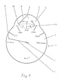
- Fig. 1 denotes the speed display element
- 2 the display element for the exhaust gas temperature
- 3 the scale of the speed display element 1
- 4 the scale of the display element 2 for the exhaust gas temperature.
- both scales 3, 4 are arranged in one plane.
- the axes of rotation 5, 6 of the display needles 7, 8 for the speed and exhaust gas temperature are also arranged in a common plane, in such a way that the display needles 7, 8 can move in opposite directions, i. H.
- the indicator needle 7 for the speed rotates clockwise
- the two display needles 7, 8 are arranged at different heights.
- the scale 4 for the exhaust gas temperature overlaps into the speed scale 3 in such a way that circles about the axes of rotation 5, 6 of the display needles 7, 8 through the tips 9, 10 of the display needles 7, 8 represent the preferred area 11 on both scales 3, 4 limit.
- the location and the size of the preferred area 11 depends on the economic working area of the internal combustion engine to be measured.
- the internal combustion engine can be operated economically when the Speed in the range between 1200 and 1900 min- 1 and at the same time the exhaust gas temperature moved between 300 ° C and 600 ° C.
- the economic operation of the internal combustion engine can thus be recognized with this display instrument by the fact that both display needles 7, 8 overlap or intersect in the preferred area 11. If one or both display needles are outside this preferred range 11, the internal combustion engine does not work economically.
- the preferred area 11 in color from the other scale areas, in such a way that the two display needles 7, 8 stand out particularly well in the area 11 from the scale.
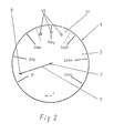
- the display element 2 for the exhaust gas temperature is no longer equipped with a display needle and a separate scale 4, but consists of light-emitting diodes 12. They are arranged in the preferred area 11 on the scale 3 of the speed display element 1. Experiments have shown that it is sufficient to divide the exhaust gas temperature range into sections and to assign a light-emitting diode 12 to each section. For the present example, this means that three light-emitting diodes 12 are arranged in the speed range of 1200 min- 1 , the first diode in the direction of rotation of the display needles 7 being in a temperature range between 300 ° and 350 ° C, the second diode between 350 ° and 450 ° C and the third lights up between 450 ° and about 550 ° C.
Landscapes
- Engineering & Computer Science (AREA)
- Chemical & Material Sciences (AREA)
- Combustion & Propulsion (AREA)
- Mechanical Engineering (AREA)
- Transportation (AREA)
- Physics & Mathematics (AREA)
- General Physics & Mathematics (AREA)
- General Engineering & Computer Science (AREA)
- Instrument Panels (AREA)
- Indicating Measured Values (AREA)
Description
- Die Erfindung bezieht sich auf eine Vorrichtung zur Anzeige des wirtschaftlichen Arbeitsbereiches einer Brennkraftmaschine, deren Augenblicksdrehzahl von einem Drehzahlmesser angezeigt wird, dessen Skala markierte Bereiche aufweist.
- Drehzahlmesser werden bei Brennkraftmaschinen dafür verwendet, um anzuzeigen, ob die Brennkraftmaschine im mechanisch zulässigen Drehzahlbereich betrieben wird. Daneben kann bei Vollast von dem Drehzahlmesser abgelesen werden, ob die Brennkraftmaschine im verbrauchsgünstigen Bereich, d. h. im Bereich des höchsten Drehmoments betrieben wird.
- In allen anderen Betriebsbereichen ist die Aussage des Drehzahlmessers hinsichtlich des verbrauchsoptimalen Bereichs nur bedingt brauchbar.
- Aufgabe der Erfindung ist es deshalb, ausgehend von der Überwachung der Drehzahl einer Brennkraftmaschine, eine Anzeigevorrichtung zu schaffen, welche bei allen Lastzuständen der Brennkraftmaschine eine zuverlässige Aussage über das Erreichen und Verweilen im verbrauchsoptimalen Bereich gestattet.
- Diese Aufgabe wird erfindungsgemäß dadurch gelöst, daß weiterhin ein Anzeigeelement für die Abgastemperatur mit einem markierten Bereich auf der zugehörigen Skala (4) vorgesehen ist, wobei sich bei Erreichen des wirtschaftlichen Bereichs sowohl die Drehzahl wie auch die Abgastemperatur jeweils in einem bevorzugten Anzeigebereich befinden, dessen Lage abhängig ist von dem Motorkennfeld der Brennkraftmaschine. Der Vorteil der Erfindung liegt darin, daß durch das Hinzufügen eines weiteren Anzeigeelements die Aussagekraft des Drehzahlmessers erweitert wird, wobei aber der bisherige Vorteil des Drehzahlmessers erhalten bleibt. Die Aufwendungen für die erfindungsgemäße Vorrichtung reduzieren sich noch, wenn eine derartige Anzeigevorrichtung für Brennkraftmaschinen verwendet wird, bei welchen die Abgastemperatur schon zu anderen Überwachungs- oder Regelfunktionen herangezogen wird, wie z. B. bei luftgekühlten Brennkraftmaschinen zur Steuerung der Kühlgebläsedrehzahl.
- Wegen des notwendigen Einbauvolumens und wegen der Forderung möglichst mit einem Blick den gewünschten Informationswert der Anzeige zu erhalten, wird in einer Weiterbildung der Erfindung vorgeschlagen, beide Anzeigen in einem Gehäuse anzuordnen und dort in einer Ebene sichtbar zu machen. Hierbei ist es von Vorteil, wenn Anzeigen über Anzeigenadeln vorgesehen werden, diese derart anzuordnen und in ihrer Länge derart auszubilden, daß sie sich bei Erreichen des wirtschaftlichen Bereiches kreuzen oder überdecken. Damit wird erreicht, daß der augenblickliche Betriebszustand der Brennkraftmaschine hinsichtlich Verbrauch ohne große Konzentration oder gar Überlegung und ohne Ablesenmüssen von konkreten Werten vollständig erfaßt werden kann.
- Eine andere Weiterbildung der Erfindung sieht vor, anstelle der digitalen Anzeige derAbgastemperatur eine analoge über Leuchtdioden vorzusehen. Die Leuchtdiodenanordnung hat den Vorteil, daß sie kleinbauend ist. Werden die Leuchtdioden - wie weiterhin vorgeschlagen ist - in der Drehzahlmesserskala angeordnet, und zwar in deren bevorzugtem Bereich, ist dadurch ebenfalls - trotz analoger Anzeige - eine optisch leicht erfaßbare Anzeigemöglichkeit gegeben.
- Versuche haben ergeben, daß es ausreichend ist, daß das Anzeigeelement für die Abgastemperatur in Bereiche unterteilt wird, und daß jedem Bereich - wie weiterhin vorgeschlagen ist - eine Leuchtdiode zugeordnet ist. Hierbei ist es zweckmäßig, die unterste Bereichsgrenze bei 300°C und die oberste bei 600°C anzusetzen, da Abgastemperaturen außerhalb dieser Anzeigegrenzen kein wirtschaftliches Arbeiten der Brennkraftmaschine gestatten.
- Im folgenden wird die Erfindung anhand eines bevorzugten Ausführungsbeispiels näher erläutert. Es stellt dar
- Fig. 1 die erfindungsgemäße Anzeigevorrichtung als Zweizeigerinstrument,
- Fig. 2 die erfindungsgemäße Anzeigevorrichtung als Kombination aus digitalem und analogem Anzeigegerät.
- In Fig. 1 ist mit 1 das Drehzahlanzeigeelement, mit 2 das Anzeigeelement für die Abgastemperatur, mit 3 die Skala des Drehzahlanzeigeelementes 1 und mit 4 die Skala des Anzeigeelementes 2 für die Abgastemperatur bezeichnet. Wie ersichtlich, sind beide Skalen 3, 4 in einer Ebene angeordnet. Die Drehachsen 5, 6 der Anzeigenadeln 7, 8 für die Drehzahl und Abgastemperatur sind ebenfalls in einer gemeinsamen Ebene angeordnet, und zwar derart, daß sich die Anzeigenadeln 7, 8 gegenläufig bewegen können, d. h. in diesem Beispiel dreht die Anzeigenadel 7 für die Drehzahl im Uhrzeigersinn, die Anzeigenadel für die Abgastemperatur in Gegenuhrzeigersinn.
- Damit ein bevorzugter Anzeigebereich 11 gebildet werden kann, sind die beiden Anzeigenadeln 7, 8 auf unterschiedlichen Höhen angeordnet. Ebenso ragt die Skala 4 für die Abgastemperatur derart überlappend in die Drehzahlskala 3 hinein, daß Kreise um die Drehachsen 5,6 der Anzeigenadeln 7, 8 durch die Spitzen 9, 10 der Anzeigenadeln 7, 8 den bevorzugten Bereich 11 auf beiden Skalen 3, 4 begrenzen. Die Lage und die Größe des bevorzugten Bereichs 11 ist abhängig vom wirtschaftlichen Arbeitsbereich der gerade zu messenden Brennkraftmaschine. In diesem Beispiel kann die Brennkraftmaschine dann wirtschaftlich betrieben werden, wenn sich die Drehzahl im Bereich zwischen 1200 und 1900 min-1 und gleichzeitig die Abgastemperatur zwischen 300°C und 600°C bewegt. Das wirtschaftliche Arbeiten der Brennkraftmaschine läßt sich mit diesem Anzeigeinstrument also daran erkennen, daß sich beide Anzeigenadeln 7, 8 im bevorzugten Bereich 11 überdecken bzw. kreuzen. Sind eine oder beide Anzeigenadeln außerhalb dieses bevorzugten Bereichs 11, arbeitet die Brennkraftmaschine nicht wirtschaftlich.
- Um eine gute optische Kontrolle der beiden Anzeigeelemente zu gewährleisten, kann es sinnvoll sein, den bevorzugten Bereich 11 farbig von den übrigen Skalenbereichen abzusetzen, und zwar derart, daß sich die beiden Anzeigenadeln 7, 8 im Bereich 11 besonders gut von der Skala abheben.
- In Fig. 2 ist das Anzeigeelement 2 für die Abgastemperatur nicht mehr mit einer Anzeigenadel und einer separaten Skala 4 ausgerüstet, sondern besteht aus Leuchtdioden 12. Sie sind in dem bevorzugten Bereich 11 in der Skala 3 des Drehzahlanzeigeelementes 1 angeordnet. Versuche haben ergeben, daß es ausreichend ist, den Abgastemperaturbereich in Abschnitte zu unterteilen und jedem Abschnitt eine Leuchtdiode 12 zuzuordnen. Dies bedeutet für das hier vorliegende Beispiel, daß drei Leuchtdioden 12 in dem Drehzahlbereich von 1200 min-1 angeordnet sind, wobei die in Drehrichtung der Anzeigenadeln 7 erste Diode in einem Temperaturbereich zwischen 300° und 350°C, die zweite Diode zwischen 350° und 450° C und die dritte zwischen 450° und etwa 550° C aufleuchtet.
- Auch hier kann es sinnvoll sein, im bevorzugten Bereich 11 in der Skala 2 von den übrigen Skalenbereichen farbig abzusetzen, z. B. in grün, und andersfarbige Leuchtdioden, z. B. in gelb, zu verwenden. Auch ist es denkbar, die einzelnen Leuchtdioden farblich unterschiedlich auszuführen.
Claims (7)
Priority Applications (1)
| Application Number | Priority Date | Filing Date | Title |
|---|---|---|---|
| AT80104516T ATE4842T1 (de) | 1979-08-29 | 1980-07-31 | Vorrichtung zur anzeige des wirtschaftlichen arbeitsbereiches einer brennkraftmaschine. |
Applications Claiming Priority (2)
| Application Number | Priority Date | Filing Date | Title |
|---|---|---|---|
| DE2934868 | 1979-08-29 | ||
| DE2934868A DE2934868C2 (de) | 1979-08-29 | 1979-08-29 | Vorrichtung zur Anzeige des wirtschaftlichen Arbeitsbereiches einer Brennkraftmaschine |
Publications (3)
| Publication Number | Publication Date |
|---|---|
| EP0024568A2 EP0024568A2 (de) | 1981-03-11 |
| EP0024568A3 EP0024568A3 (en) | 1982-02-17 |
| EP0024568B1 true EP0024568B1 (de) | 1983-09-28 |
Family
ID=6079547
Family Applications (1)
| Application Number | Title | Priority Date | Filing Date |
|---|---|---|---|
| EP80104516A Expired EP0024568B1 (de) | 1979-08-29 | 1980-07-31 | Vorrichtung zur Anzeige des wirtschaftlichen Arbeitsbereiches einer Brennkraftmaschine |
Country Status (3)
| Country | Link |
|---|---|
| EP (1) | EP0024568B1 (de) |
| AT (1) | ATE4842T1 (de) |
| DE (1) | DE2934868C2 (de) |
Families Citing this family (2)
| Publication number | Priority date | Publication date | Assignee | Title |
|---|---|---|---|---|
| DE2934839A1 (de) * | 1979-08-29 | 1981-03-19 | Klöckner-Humboldt-Deutz AG, 5000 Köln | Anzeigeelement fuer den belastungszustand eines motors |
| SE519083C2 (sv) * | 2001-05-17 | 2003-01-07 | Scania Cv Ab | Varvtalsmätare för ett fordon |
Family Cites Families (9)
| Publication number | Priority date | Publication date | Assignee | Title |
|---|---|---|---|---|
| US2040778A (en) * | 1932-01-28 | 1936-05-12 | Doherty Res Co | Combustion efficiency adjusting apparatus |
| FR807122A (fr) * | 1935-09-27 | 1937-01-05 | Peugeot | Procédé et appareil permettant la lecture directe de la consommation instantanée de carburant des moteurs |
| FR951927A (fr) * | 1947-08-06 | 1949-11-07 | Perfectionnements apportés aux appareils de mesure à aiguille et graduation chiffrée | |
| CH321171A (de) * | 1953-03-25 | 1957-04-30 | Elima Fabrik Fuer Elektrische | Messinstrument mit zwei gleichsinnig drehenden Messwerken |
| DE1573833B2 (de) * | 1960-02-10 | 1972-02-17 | Siemens AG, 1000 Berlin u 8000 München | Einrichtung zur anzeige der zulaessigen belastungsaenderung von dampf und gasturbinen |
| US3154060A (en) * | 1962-11-05 | 1964-10-27 | Hundere Alf | Reciprocating-piston gasoline engine fuel-air ratio control |
| DE1506630B2 (de) * | 1967-04-15 | 1972-01-27 | Dormer AG, 7990 Friedrichshafen | Fluginstrumentierung mit elektronischer. anzeige |
| DE2724927A1 (de) * | 1977-06-02 | 1978-12-07 | Sachs Systemtechnik Gmbh | Vorrichtung zur anzeige einer hoechstzulaessigen motor-grenzdrehzahl bzw. gangbezogenen grenzgeschwindigkeit |
| DE2748375A1 (de) * | 1977-10-28 | 1979-05-03 | Sachs Systemtechnik Gmbh | Vorrichtung zur anzeige einer hoechstzulaessigen motorgrenzdrehzahl |
-
1979
- 1979-08-29 DE DE2934868A patent/DE2934868C2/de not_active Expired
-
1980
- 1980-07-31 EP EP80104516A patent/EP0024568B1/de not_active Expired
- 1980-07-31 AT AT80104516T patent/ATE4842T1/de not_active IP Right Cessation
Also Published As
| Publication number | Publication date |
|---|---|
| DE2934868C2 (de) | 1984-10-04 |
| EP0024568A3 (en) | 1982-02-17 |
| ATE4842T1 (de) | 1983-10-15 |
| DE2934868A1 (de) | 1981-03-12 |
| EP0024568A2 (de) | 1981-03-11 |
Similar Documents
| Publication | Publication Date | Title |
|---|---|---|
| DE2252854C3 (de) | Instrumententräger für Kraftfahrzeuge u.dgl | |
| DE19621896A1 (de) | Drehzahlmesser mit Ökonometer | |
| DE3003655C2 (de) | Anzeigevorrichtung für quasianaloge und Zeichen-Anzeige | |
| DE60319698T2 (de) | Vorrichtung zur anzeige des betriebszustands eines fahrzeugs | |
| DE4125372C1 (en) | Monitoring aircraft power unit esp. helicopter gas turbine drives - indicating only critical instantaneous parameters on display and warning of values outside set ranges | |
| DE7922585U1 (de) | Instrumentenbrett fuer kraftfahrzeug | |
| EP0024568A2 (de) | Vorrichtung zur Anzeige des wirtschaftlichen Arbeitsbereiches einer Brennkraftmaschine | |
| DE19739037A1 (de) | Verstellbare Anzeigemarkierung | |
| DE112006002108T5 (de) | Anzeige-Wechsel-Kombiinstrument | |
| DE2621042B2 (de) | Anzeigeskala für digital anzeigende Uhren und/oder Instrumente | |
| DE19914597A1 (de) | Anzeigeinstrument für Kraftfahrzeuge | |
| DE4418398A1 (de) | Anzeigevorrichtung für ein Fahrzeug | |
| DE673563C (de) | Anordnung von Sammelanzeigegeraeten | |
| DE202016104169U1 (de) | Instrumenten-Nadelanzeigevorichtung zum Bereitstellen einer visuellen Anzeige der Momentankraftstoffwirtschaftlichkeit | |
| DE2934839A1 (de) | Anzeigeelement fuer den belastungszustand eines motors | |
| DE19749084B4 (de) | Anzeigevorrichtung | |
| DE102012200154B4 (de) | Anzeigegerät für ein Kraftfahrzeug | |
| DE2802684C2 (de) | Meßanzeigegerät | |
| DE3134121A1 (de) | Einrichtung zur anzeige des wartungszeitpunktes eines kraftfahrzeugs | |
| DE2904758A1 (de) | Elektronische messwertanzeigevorrichtung | |
| DE2834971A1 (de) | Anzeigeeinrichtung zum anzeigen der fahrgeschwindigkeit eines fahrzeugs | |
| DE69700798T2 (de) | Mehrzweck-Anzeigevorrichtung | |
| Bedrosian | An analysis of vocational interests at two levels of management. | |
| DE174418C (de) | ||
| CH685727A5 (de) | Anzeigevorrichtung. |
Legal Events
| Date | Code | Title | Description |
|---|---|---|---|
| PUAI | Public reference made under article 153(3) epc to a published international application that has entered the european phase |
Free format text: ORIGINAL CODE: 0009012 |
|
| AK | Designated contracting states |
Designated state(s): AT FR GB IT SE |
|
| PUAL | Search report despatched |
Free format text: ORIGINAL CODE: 0009013 |
|
| 17P | Request for examination filed |
Effective date: 19811023 |
|
| AK | Designated contracting states |
Designated state(s): AT FR GB IT SE |
|
| ITF | It: translation for a ep patent filed | ||
| GRAA | (expected) grant |
Free format text: ORIGINAL CODE: 0009210 |
|
| AK | Designated contracting states |
Designated state(s): AT FR GB IT SE |
|
| REF | Corresponds to: |
Ref document number: 4842 Country of ref document: AT Date of ref document: 19831015 Kind code of ref document: T |
|
| ET | Fr: translation filed | ||
| PGFP | Annual fee paid to national office [announced via postgrant information from national office to epo] |
Ref country code: SE Payment date: 19840630 Year of fee payment: 5 |
|
| PLBE | No opposition filed within time limit |
Free format text: ORIGINAL CODE: 0009261 |
|
| STAA | Information on the status of an ep patent application or granted ep patent |
Free format text: STATUS: NO OPPOSITION FILED WITHIN TIME LIMIT |
|
| 26N | No opposition filed | ||
| PG25 | Lapsed in a contracting state [announced via postgrant information from national office to epo] |
Ref country code: SE Effective date: 19890801 |
|
| PGFP | Annual fee paid to national office [announced via postgrant information from national office to epo] |
Ref country code: FR Payment date: 19910610 Year of fee payment: 12 Ref country code: AT Payment date: 19910610 Year of fee payment: 12 |
|
| PGFP | Annual fee paid to national office [announced via postgrant information from national office to epo] |
Ref country code: GB Payment date: 19910612 Year of fee payment: 12 |
|
| PG25 | Lapsed in a contracting state [announced via postgrant information from national office to epo] |
Ref country code: GB Effective date: 19920731 Ref country code: AT Effective date: 19920731 |
|
| GBPC | Gb: european patent ceased through non-payment of renewal fee |
Effective date: 19920731 |
|
| PG25 | Lapsed in a contracting state [announced via postgrant information from national office to epo] |
Ref country code: FR Effective date: 19930331 |
|
| REG | Reference to a national code |
Ref country code: FR Ref legal event code: ST |
|
| EUG | Se: european patent has lapsed |
Ref document number: 80104516.2 Effective date: 19900418 |