EP0024551B1 - Process and apparatus for removing sulfur dioxide from industrial waste gas - Google Patents
Process and apparatus for removing sulfur dioxide from industrial waste gas Download PDFInfo
- Publication number
- EP0024551B1 EP0024551B1 EP80104375A EP80104375A EP0024551B1 EP 0024551 B1 EP0024551 B1 EP 0024551B1 EP 80104375 A EP80104375 A EP 80104375A EP 80104375 A EP80104375 A EP 80104375A EP 0024551 B1 EP0024551 B1 EP 0024551B1
- Authority
- EP
- European Patent Office
- Prior art keywords
- spray
- waste gas
- gas
- aqueous absorbent
- interfering
- Prior art date
- Legal status (The legal status is an assumption and is not a legal conclusion. Google has not performed a legal analysis and makes no representation as to the accuracy of the status listed.)
- Expired
Links
Images


Classifications
-
- B—PERFORMING OPERATIONS; TRANSPORTING
- B01—PHYSICAL OR CHEMICAL PROCESSES OR APPARATUS IN GENERAL
- B01D—SEPARATION
- B01D53/00—Separation of gases or vapours; Recovering vapours of volatile solvents from gases; Chemical or biological purification of waste gases, e.g. engine exhaust gases, smoke, fumes, flue gases, aerosols
- B01D53/34—Chemical or biological purification of waste gases
- B01D53/46—Removing components of defined structure
- B01D53/48—Sulfur compounds
- B01D53/50—Sulfur oxides
- B01D53/501—Sulfur oxides by treating the gases with a solution or a suspension of an alkali or earth-alkali or ammonium compound
-
- B—PERFORMING OPERATIONS; TRANSPORTING
- B01—PHYSICAL OR CHEMICAL PROCESSES OR APPARATUS IN GENERAL
- B01D—SEPARATION
- B01D53/00—Separation of gases or vapours; Recovering vapours of volatile solvents from gases; Chemical or biological purification of waste gases, e.g. engine exhaust gases, smoke, fumes, flue gases, aerosols
- B01D53/14—Separation of gases or vapours; Recovering vapours of volatile solvents from gases; Chemical or biological purification of waste gases, e.g. engine exhaust gases, smoke, fumes, flue gases, aerosols by absorption
- B01D53/18—Absorbing units; Liquid distributors therefor
Definitions
- This invention relates to the removal of sulfur dioxide from industrial waste gas, for example combustion gas from steam power plants, by wet scrubbing the gas in a horizontal, elongate, gas-liquid contactor with an aqueous absorbent.
- Horizontal, elongate spray scrubbers devoid of internal packing are effective gas-liquid contactors for removal of sulfur dioxide from large volume flows of waste gas.
- a particularly effective scrubber of this type utilizes aqueous absorbent sprays directed across the chamber substantially perpendicular to the horizontal flow of waste gas as more fully described in US ⁇ A ⁇ 3,948,608 to Alexander Weir, Jr.
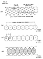
- a commercial embodiment of this scrubber has a plurality of spray nozzles positioned at the top of the scrubber as illustrated in Figure 1. The nozzles are arranged in stages as illustrated in Figure 2 and direct aqueous absorbent substantially vertically downward across cross sections of the gas flow path along the length of the scrubber. Typically, from four to six stages are used.
- Individual headers convey absorbent to the nozzles of each stage in an amount necessary to satisfy the gas/liquid flow rate ratio (G/L) required for the particular installation.
- This amount may be, for example, 700 liters per second in each stage discharged through 50 nozzles having 90 degree cone angles spaced 0.163 meters apart along the individual header.
- Sauter mean diameter is the diameter of a droplet whose ratio of volume to surface area is equal to that of the entire spray.
- Mass transfer characteristics of other absorbents are generally between the above-mentioned extremes. Quite commonly, a particular system will be liquid phase mass transfer limited proximate the scrubber gas inlet and gas phase mass transfer limited proximate the gas outlet because of the decreasing sulfur dioxide concentration along the waste gas flow path.
- interfering spray density (I.S.D.) calculated as the average aqueous absorbent flow rate per unit area at any horizontal plane. A method for this calculation is recited later in this specification.
- the interfering spray density (I.S.D.) attains a maximum value at a short distance below the horizontal plane of initial interference of the spray droplets. Most importantly, we have found that the detrimental effects of spray interference may be significantly reduced by maintaining the I.S.D. below a critical value.
- a process and apparatus are provided for removal of sulfur dioxide from waste gas by passing the gas through a horizontal, elongate, gas-liquid contactor having a substantially unrestricted flow path and passing aqueous absorbent substantially vertically downward through the waste gas in a plurality of interfering cones of spray droplets having an initial Sauter mean diameter of from 800 to 2000 ,um wherein the aqueous absorbent in at least a longitudinal portion of the contactor has a maximum I.S.D. less than about 100 liters per second per square meter at any horizontal plane.
- the waste gas treated by the process and apparatus of this invention is sulfur dioxide containing gas in large volume, typically from about 50 to about 800 actual cubic meters per second, discharged from sources such as steam power plants, smelters, refineries, pulp mills, or chemical operations.
- Combustion gas from coal fired power plants is particularly in point.
- This gas is typically composed of nitrogen, carbon dioxide, oxygen and smaller amounts of other gases including sulfur dioxide in concentrations of from about 200 to about 6000 parts per million by volume.
- the gas to be scrubbed also normally contains particulate matter such as fly ash which varies in quantity according to the waste gas source and the extent of upstream removal by, for example, precipitators.
- the gas-liquid contacting zone is, as previously mentioned, a horizontal, elongate contacting chamber or scrubber having a waste gas inlet at one end and a cleaned gas outlet at the other end.
- the contactor may be internally baffled to direct gas flow in a somewhat sinusoidal flow path in which case the gas flow is, to a degree, countercurrent to the downward flow of aqueous absorbent
- the contact zone has a horizontal gas flow path with no restriction to either gas or liquid flow such as packing, trays, mesh, baffles, or the like.
- the chamber is preferably substantially rectangular in cross section across the gas flow path with a height of from about 3 to about 9 meters and a ratio of height to width of from about 0.4 to about 3.0.
- the chamber will also have liquid collection and discharge means disposed at the bottom thereof for further processing and recycle of spent or SOZ-laden absorbent.
- the collection and discharge means may Include reaction tanks that are attached to the scrubber as sumps.
- the contacting zone includes a plurality of spray nozzles for aqueous absorbent positioned at the top of the scrubber to direct a corresponding plurality of interfering cones of spray droplets substantially vertically downward through the waste gas.
- the liquid flow rate for various groups of nozzles along the length of the scrubber and the total aqueous absorbent flow rate within the contacting zone is a function of the desired S0 2 removal efficiency as well as the other variables expressed in equation (2).
- a volume flow rate ratio of waste gas to aqueous absorbent of from about 200:1 to about 5000:1 per meter of length of the contacting zone is suitable for the range of S0 2 concentrations typically existing in this region.
- the spray nozzles be substantially uniformly horizontally spaced apart so that the aqueous absorbent has a substantially uniform interfering spray density at any horizontal plane within the longitudinal portion, not only for control and optimization of liquid flow rate but also to avoid gas channeling in the contacting chamber.
- Gas velocity may range from about 3 to about 10 meters per second. Parameters for gas velocity, scrubber height, and spray nozzles should be selected to yield an average relative velocity between waste gas and aqueous absorbent of from about 7 to about 14 meters per second and a residence time of aqueous absorbent in the contacting zone of from about 0.3 to about 1.5 seconds.
- aqueous absorbents for S0 2 removal systems vary considerably.
- the active components of these absorbents are well known and include sodium carbonate, sodium sulfite, calcium oxide or hydroxide, and calcium carbonate.
- the calcium reagents form calcium sulfite and, when oxygen is present, calcium sulfate upon reaction with S0 2 absorbed in water as sulfurous acid. They are commercially popular because of their low cost, but when used alone, have relatively high liquid phase mass transfer resistance.
- Spray droplets originate from the nozzles as distinct cones of spray droplets having an initial Sauter mean diameter of from about 800 to about 2000 microns. While a variety of individual nozzle spray patterns may be utilized, we prefer to use nozzles which form substantially circular cones of spray having an included angle of from about 80 to about 120 degrees. Preferred nozzles have relatively uniform spray density, small initial drop size, and high flow/low pressure drop characteristics. Preferably, each nozzle discharges aqueous absorbent at a rate of from about 9 to 19 liters per second at an initial droplet velocity of from about 9 to about 21 meters per second. The nozzle pressure should be sufficient to produce droplets within the mean diameter range recited above and will typically be from about 2 to about 3.5 kilograms per square centimeter absolute.
- the maximum I.S.D. is preferably about 45 liters per second per square meter. From a technical viewpoint, there is no lower limit on the maximum I.S.D., however economic considersations place this value at about 10 liters per second per square meter.
- the preferred minimum nozzle spacing is about 0.4 meters. Maximum nozzle spacing is limited by considerations of gas channeling and economic scrubber design rather than interfering spray density. Within the range of spray cone angles recited, the maximum preferred nozzle spacing is about 0.85 meters.
- the longitudinal portion of the contactor in which the maximum I.S.D. is limited is most effectively that portion in which S0 2 removal is gas phase mass transfer limited. This portion will generally exist proximate the cleaned gas outlet. Correspondingly, there is generally no gas phase transfer limitation proximate the waste gas inlet. In this region, it may be desirable to utilize low G/L ratios and high spray density according to the prior art configuration illustrated in Figure 2.
- Table I provides a summary of calculated comparative performance of an S0 2 absorber designed both with the prior art spray arrangement of Figure 2 and with the Figure 4 spray arrangement which is an embodiment of the present invention.
- These spray arrangements result in interfering spray densities, calculated by the method described in the appendix, that are plotted in Figure 7 as a function of the vertical distance below the nozzle arrays.
- the maximum I.S.D. for the prior art nozzle arrangement is 276 liters per second per square meter which, according to Figure 6, corresponds to a droplet mean diameter greater than 2.5x 10- 3 meters.
- the S0 2 removal per stage is found to be less than 68% for the prior art nozzle arrangement and 83% for the nozzle arrangement of Figure 4.
- this increase in performance results in a decrease in the number of spray stages required for nearly complete S0 2 removal from over four to three.
- the reduction in number of spray stages results in lower initial cost of the scrubber installation as well as significantly reduced cost for circulating the lesser amount of aqueous absorbent.
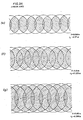
- part (a) which illustrates a vertical cross-section through a row of 120° spray cones with S spacing along the row
- the interfering spray density (I.S.D) at any horizontal plane y is the weighted average of spray densities existing at that plane excluding the fraction having no interference.
- the I.S.D. may be calculated as the summation of the multiple, fractional densities that exist at the plane in question: SD yl is the spray density for areas of intereference involving i cones of spray at the plane y and is equal to where:
Landscapes
- Chemical & Material Sciences (AREA)
- Engineering & Computer Science (AREA)
- Analytical Chemistry (AREA)
- General Chemical & Material Sciences (AREA)
- Oil, Petroleum & Natural Gas (AREA)
- Chemical Kinetics & Catalysis (AREA)
- Health & Medical Sciences (AREA)
- Biomedical Technology (AREA)
- Environmental & Geological Engineering (AREA)
- Treating Waste Gases (AREA)
- Gas Separation By Absorption (AREA)
Applications Claiming Priority (2)
| Application Number | Priority Date | Filing Date | Title |
|---|---|---|---|
| US06/061,225 US4269812A (en) | 1979-07-27 | 1979-07-27 | Horizontal cross-flow scrubber for sulfur oxide removal |
| US61225 | 1979-07-27 |
Publications (3)
| Publication Number | Publication Date |
|---|---|
| EP0024551A2 EP0024551A2 (en) | 1981-03-11 |
| EP0024551A3 EP0024551A3 (en) | 1981-03-18 |
| EP0024551B1 true EP0024551B1 (en) | 1983-09-21 |
Family
ID=22034443
Family Applications (1)
| Application Number | Title | Priority Date | Filing Date |
|---|---|---|---|
| EP80104375A Expired EP0024551B1 (en) | 1979-07-27 | 1980-07-24 | Process and apparatus for removing sulfur dioxide from industrial waste gas |
Country Status (7)
| Country | Link |
|---|---|
| US (1) | US4269812A (https=) |
| EP (1) | EP0024551B1 (https=) |
| JP (1) | JPS5621628A (https=) |
| AU (1) | AU534155B2 (https=) |
| CA (1) | CA1124037A (https=) |
| DE (1) | DE3064930D1 (https=) |
| ZA (1) | ZA803776B (https=) |
Cited By (1)
| Publication number | Priority date | Publication date | Assignee | Title |
|---|---|---|---|---|
| DE10323355A1 (de) * | 2003-05-21 | 2004-12-09 | Kretzschmar, Axel, Dr.Rer.Nat.Habil. | Verfahren, Anordnung und Vorrichtung zur Reinigung strömender Gase |
Families Citing this family (32)
| Publication number | Priority date | Publication date | Assignee | Title |
|---|---|---|---|---|
| GB2115309A (en) * | 1982-02-25 | 1983-09-07 | Dresser Ind | Improvements in or relating to absorption of pollutant material from a polluted gas |
| ES292673Y (es) * | 1986-03-03 | 1987-03-01 | Depurator, S.A. | Dispositivo depurador de gases de combustion |
| US6174498B1 (en) | 1991-10-28 | 2001-01-16 | Us Filter/Rj Environmental, Inc. | Odor control system |
| US5876662A (en) * | 1991-10-28 | 1999-03-02 | Us Filter/Rj Environmental, Inc. | Odor control system |
| KR100264382B1 (ko) * | 1992-03-18 | 2000-08-16 | 폰투스 브레뎀 | 기체 청정 또는 기체 냉각용 장치 및 그 방법 |
| US5403568A (en) * | 1993-03-05 | 1995-04-04 | Dravo Lime Company | Horizontal wet scrubbing apparatus and method for removing sulfur dioxide from a gaseous stream |
| US5582807A (en) * | 1994-11-04 | 1996-12-10 | Tek-Kol | Method and apparatus for removing particulate and gaseous pollutants from a gas stream |
| US6019818A (en) * | 1996-09-27 | 2000-02-01 | G.F.K. Consulting, Ltd. | Combination quenching and scrubbing process and apparatus therefor |
| DE19651074A1 (de) * | 1996-12-09 | 1998-06-10 | Abb Research Ltd | Verfahren und Einrichtung zur nassen Rauchgasentschwefelung |
| US6102377A (en) * | 1997-02-26 | 2000-08-15 | Abb Environmental Services, Division Of Abb Flakt, Inc. | Wet scrubbing spray apparatus for removing sulfur oxides from combustion effluents |
| BE1011030A3 (nl) * | 1997-03-04 | 1999-04-06 | Seghers Engineering | Inrichting voor rookgaszuivering met behulp van persluchtverstuivers. |
| RU2150314C1 (ru) * | 1999-06-10 | 2000-06-10 | Асадов Георгий Арменакович | Установка для тепломассообменных процессов с горизонтальным противотоком газа и жидкости |
| US6923852B2 (en) * | 2002-10-24 | 2005-08-02 | The Babcock & Wilcox Company | Flue gas desulfurization system with a stepped tray |
| US8398059B2 (en) | 2005-02-14 | 2013-03-19 | Neumann Systems Group, Inc. | Gas liquid contactor and method thereof |
| US8864876B2 (en) | 2005-02-14 | 2014-10-21 | Neumann Systems Group, Inc. | Indirect and direct method of sequestering contaminates |
| US7379487B2 (en) | 2005-02-14 | 2008-05-27 | Neumann Information Systems, Inc. | Two phase reactor |
| US8113491B2 (en) * | 2005-02-14 | 2012-02-14 | Neumann Systems Group, Inc. | Gas-liquid contactor apparatus and nozzle plate |
| US7866638B2 (en) * | 2005-02-14 | 2011-01-11 | Neumann Systems Group, Inc. | Gas liquid contactor and effluent cleaning system and method |
| US20060185517A1 (en) * | 2005-02-22 | 2006-08-24 | Nagel Daniel J | Multi-stage odor scrubber |
| EP1707875A1 (de) | 2005-03-18 | 2006-10-04 | Lurgi Lentjes AG | Rauchgasreinigungsvorrichtung mit verbesserter Oxidationseinrichtung im Waschflüssigkeitssumpf |
| EP1707876A1 (de) | 2005-03-18 | 2006-10-04 | Lurgi Lentjes AG | Im wesentlichen horizontal durchströmte Rauchgasreinigungsvorrichtung |
| US7645430B2 (en) * | 2007-10-08 | 2010-01-12 | Alcoa Inc. | Systems and methods for removing gaseous pollutants from a gas stream |
| US8226754B2 (en) * | 2008-10-15 | 2012-07-24 | Urs Corporation | Low cost wet lime/limestone/sodium FGD system |
| IT1395291B1 (it) * | 2009-02-23 | 2012-09-05 | Mazzega | Impianto per il recupero energetico. |
| IT1392986B1 (it) * | 2009-02-23 | 2012-04-02 | Eberle | Dispositivo per il recupero energetico. |
| US8894748B2 (en) | 2012-08-21 | 2014-11-25 | Alcoa Inc. | Systems and methods for removing particulate matter from a gas stream |
| US9327237B2 (en) | 2014-07-23 | 2016-05-03 | Alcoa Inc. | Systems and methods for removing sulfur dioxide from a gas stream |
| US10239016B2 (en) | 2016-12-07 | 2019-03-26 | Nuorganics LLC | Systems and methods for nitrogen recovery from a gas stream |
| CA2992063A1 (en) | 2017-01-16 | 2018-07-16 | Nuorganics LLC | Systems and methods for recovering nitrogenous compounds from a gas stream |
| JP6104491B1 (ja) * | 2017-01-20 | 2017-03-29 | 三菱日立パワーシステムズ株式会社 | 船舶用脱硫装置および該船舶用脱硫装置を搭載した船舶 |
| IT201700090652A1 (it) * | 2017-08-04 | 2019-02-04 | Nino Meogrossi | Dispositivo abbattitore di fumi, polveri e odori di un fluido aeriforme. |
| US11214489B1 (en) * | 2020-11-28 | 2022-01-04 | Ceres Technology, LLC | Crossflow scrubbing method and apparatus to produce a product such as potassium thiosulfate or ammonium thiosulfate |
Citations (1)
| Publication number | Priority date | Publication date | Assignee | Title |
|---|---|---|---|---|
| US3948608A (en) * | 1972-03-24 | 1976-04-06 | Weir Jr Alexander | Apparatus for treating stack gases |
Family Cites Families (9)
| Publication number | Priority date | Publication date | Assignee | Title |
|---|---|---|---|---|
| US2215707A (en) * | 1938-09-19 | 1940-09-24 | Matanovich-Manov Mateo | Stack gas smoke control apparatus |
| BE619761A (https=) * | 1961-07-05 | |||
| US3616597A (en) * | 1970-05-11 | 1971-11-02 | Solomon L Stewart | Method for treating and purifying air |
| DE2321976A1 (de) * | 1973-05-02 | 1974-11-21 | Johann Renneberg | Verfahren und vorrichtung zum reinigen von heissen abgasen |
| JPS5080271A (https=) * | 1973-11-14 | 1975-06-30 | ||
| US3985860A (en) * | 1975-09-22 | 1976-10-12 | Pullman Incorporated | Method for oxidation of SO2 scrubber sludge |
| US4039307A (en) * | 1976-02-13 | 1977-08-02 | Envirotech Corporation | Countercurrent flow horizontal spray absorber |
| DE2606403A1 (de) * | 1976-02-18 | 1977-08-25 | Gerhard Beil | Vorrichtung zum zerstaeuben von fluessigkeiten |
| JPS5612996Y2 (https=) * | 1976-07-21 | 1981-03-26 |
-
1979
- 1979-07-27 US US06/061,225 patent/US4269812A/en not_active Expired - Lifetime
-
1980
- 1980-06-25 ZA ZA00803776A patent/ZA803776B/xx unknown
- 1980-07-04 JP JP9161480A patent/JPS5621628A/ja active Granted
- 1980-07-08 AU AU60206/80A patent/AU534155B2/en not_active Ceased
- 1980-07-15 CA CA356,184A patent/CA1124037A/en not_active Expired
- 1980-07-24 DE DE8080104375T patent/DE3064930D1/de not_active Expired
- 1980-07-24 EP EP80104375A patent/EP0024551B1/en not_active Expired
Patent Citations (1)
| Publication number | Priority date | Publication date | Assignee | Title |
|---|---|---|---|---|
| US3948608A (en) * | 1972-03-24 | 1976-04-06 | Weir Jr Alexander | Apparatus for treating stack gases |
Cited By (1)
| Publication number | Priority date | Publication date | Assignee | Title |
|---|---|---|---|---|
| DE10323355A1 (de) * | 2003-05-21 | 2004-12-09 | Kretzschmar, Axel, Dr.Rer.Nat.Habil. | Verfahren, Anordnung und Vorrichtung zur Reinigung strömender Gase |
Also Published As
| Publication number | Publication date |
|---|---|
| AU534155B2 (en) | 1984-01-05 |
| ZA803776B (en) | 1981-06-24 |
| JPS6315007B2 (https=) | 1988-04-02 |
| AU6020680A (en) | 1981-01-29 |
| US4269812A (en) | 1981-05-26 |
| EP0024551A3 (en) | 1981-03-18 |
| EP0024551A2 (en) | 1981-03-11 |
| DE3064930D1 (en) | 1983-10-27 |
| CA1124037A (en) | 1982-05-25 |
| JPS5621628A (en) | 1981-02-28 |
Similar Documents
| Publication | Publication Date | Title |
|---|---|---|
| EP0024551B1 (en) | Process and apparatus for removing sulfur dioxide from industrial waste gas | |
| US4343771A (en) | Horizontal cross-flow scrubber | |
| US4039307A (en) | Countercurrent flow horizontal spray absorber | |
| US3745751A (en) | Sulfur dioxide collection system | |
| US5403568A (en) | Horizontal wet scrubbing apparatus and method for removing sulfur dioxide from a gaseous stream | |
| US5486341A (en) | Entrainment separator for high velocity gases | |
| US4315872A (en) | Plate column | |
| US5464459A (en) | Chevron type mist eliminator and system | |
| CA2446171C (en) | Flue gas desulfurization system with a stepped tray | |
| WO1994023826A1 (fr) | Dispositif de desulfuration a voie humide d'effluents gazeux | |
| EA001995B1 (ru) | Скруббер для очистки дымовых газов | |
| PL182489B1 (pl) | Sposób i urządzenie do płukania gazów dla redukcji stężenia SO w spalinach | |
| JP3523865B2 (ja) | ガス浄化法またはガス冷却法および装置 | |
| US4293524A (en) | Method and apparatus for cooling and neutralizing acid gases | |
| US5840263A (en) | Flue gas treating process and system | |
| CN104548881A (zh) | 用于湿式脱硫喷洒塔的方法及设备 | |
| EP2300126B1 (de) | Anlage und verfahren zur absorption von schadstoffen in gasen | |
| RU97100157A (ru) | Сепаратор унесенной жидкости для высокоскоростных газов и для повторного нагрева газов, выходящих из скруббера | |
| KR970007058B1 (ko) | 연도가스의 오염물제거처리를 위한 포화 및 가습방법 | |
| JP3757437B2 (ja) | 活性炭触媒反応装置およびこれを用いた排煙脱硫装置並びに脱硫方法 | |
| US4330512A (en) | Methods for treating a gas flow containing sulfur oxide | |
| US4028077A (en) | Mist eliminator | |
| EP0235713B1 (en) | Method for removing so2 from gas streams | |
| CA1091144A (en) | Wet gas scrubber for micron and sub-micron particulates | |
| US4375455A (en) | Method and apparatus for cooling and neutralizing acid gases |
Legal Events
| Date | Code | Title | Description |
|---|---|---|---|
| PUAI | Public reference made under article 153(3) epc to a published international application that has entered the european phase |
Free format text: ORIGINAL CODE: 0009012 |
|
| PUAL | Search report despatched |
Free format text: ORIGINAL CODE: 0009013 |
|
| AK | Designated contracting states |
Designated state(s): BE DE FR GB IT NL |
|
| AK | Designated contracting states |
Designated state(s): BE DE FR GB IT NL |
|
| 17P | Request for examination filed |
Effective date: 19810701 |
|
| ITF | It: translation for a ep patent filed | ||
| GRAA | (expected) grant |
Free format text: ORIGINAL CODE: 0009210 |
|
| AK | Designated contracting states |
Designated state(s): BE DE FR GB IT NL |
|
| REF | Corresponds to: |
Ref document number: 3064930 Country of ref document: DE Date of ref document: 19831027 |
|
| ET | Fr: translation filed | ||
| PLBE | No opposition filed within time limit |
Free format text: ORIGINAL CODE: 0009261 |
|
| STAA | Information on the status of an ep patent application or granted ep patent |
Free format text: STATUS: NO OPPOSITION FILED WITHIN TIME LIMIT |
|
| 26N | No opposition filed | ||
| PGFP | Annual fee paid to national office [announced via postgrant information from national office to epo] |
Ref country code: NL Payment date: 19870731 Year of fee payment: 8 |
|
| PG25 | Lapsed in a contracting state [announced via postgrant information from national office to epo] |
Ref country code: NL Effective date: 19890201 |
|
| NLV4 | Nl: lapsed or anulled due to non-payment of the annual fee | ||
| PGFP | Annual fee paid to national office [announced via postgrant information from national office to epo] |
Ref country code: FR Payment date: 19890614 Year of fee payment: 10 |
|
| PGFP | Annual fee paid to national office [announced via postgrant information from national office to epo] |
Ref country code: DE Payment date: 19890616 Year of fee payment: 10 |
|
| PGFP | Annual fee paid to national office [announced via postgrant information from national office to epo] |
Ref country code: GB Payment date: 19890630 Year of fee payment: 10 |
|
| PGFP | Annual fee paid to national office [announced via postgrant information from national office to epo] |
Ref country code: BE Payment date: 19890714 Year of fee payment: 10 |
|
| ITTA | It: last paid annual fee | ||
| PG25 | Lapsed in a contracting state [announced via postgrant information from national office to epo] |
Ref country code: GB Effective date: 19900724 |
|
| PG25 | Lapsed in a contracting state [announced via postgrant information from national office to epo] |
Ref country code: BE Effective date: 19900731 |
|
| BERE | Be: lapsed |
Owner name: THE M. W. KELLOGG CY Effective date: 19900731 |
|
| GBPC | Gb: european patent ceased through non-payment of renewal fee | ||
| PG25 | Lapsed in a contracting state [announced via postgrant information from national office to epo] |
Ref country code: FR Effective date: 19910329 |
|
| PG25 | Lapsed in a contracting state [announced via postgrant information from national office to epo] |
Ref country code: DE Effective date: 19910403 |
|
| REG | Reference to a national code |
Ref country code: FR Ref legal event code: ST |