EP0023909B1 - Vorrichtung zum einklappen eines hinteren rotor-kabelantriebs - Google Patents
Vorrichtung zum einklappen eines hinteren rotor-kabelantriebs Download PDFInfo
- Publication number
- EP0023909B1 EP0023909B1 EP80900354A EP80900354A EP0023909B1 EP 0023909 B1 EP0023909 B1 EP 0023909B1 EP 80900354 A EP80900354 A EP 80900354A EP 80900354 A EP80900354 A EP 80900354A EP 0023909 B1 EP0023909 B1 EP 0023909B1
- Authority
- EP
- European Patent Office
- Prior art keywords
- link
- pylon
- tail cone
- tail
- pivot
- Prior art date
- Legal status (The legal status is an assumption and is not a legal conclusion. Google has not performed a legal analysis and makes no representation as to the accuracy of the status listed.)
- Expired
Links
- 230000004308 accommodation Effects 0.000 title 1
- 230000007246 mechanism Effects 0.000 abstract description 6
- 238000005452 bending Methods 0.000 description 2
- 230000002411 adverse Effects 0.000 description 1
- 238000013459 approach Methods 0.000 description 1
- 238000010276 construction Methods 0.000 description 1
- 230000001627 detrimental effect Effects 0.000 description 1
- 238000009434 installation Methods 0.000 description 1
Images

Classifications
-
- B—PERFORMING OPERATIONS; TRANSPORTING
- B64—AIRCRAFT; AVIATION; COSMONAUTICS
- B64C—AEROPLANES; HELICOPTERS
- B64C1/00—Fuselages; Constructional features common to fuselages, wings, stabilising surfaces or the like
- B64C1/06—Frames; Stringers; Longerons ; Fuselage sections
- B64C1/061—Frames
- B64C1/063—Folding or collapsing to reduce overall dimensions, e.g. foldable tail booms
-
- B—PERFORMING OPERATIONS; TRANSPORTING
- B64—AIRCRAFT; AVIATION; COSMONAUTICS
- B64C—AEROPLANES; HELICOPTERS
- B64C27/00—Rotorcraft; Rotors peculiar thereto
- B64C27/54—Mechanisms for controlling blade adjustment or movement relative to rotor head, e.g. lag-lead movement
- B64C27/78—Mechanisms for controlling blade adjustment or movement relative to rotor head, e.g. lag-lead movement in association with pitch adjustment of blades of anti-torque rotor
-
- B—PERFORMING OPERATIONS; TRANSPORTING
- B64—AIRCRAFT; AVIATION; COSMONAUTICS
- B64C—AEROPLANES; HELICOPTERS
- B64C27/00—Rotorcraft; Rotors peculiar thereto
- B64C27/04—Helicopters
-
- Y—GENERAL TAGGING OF NEW TECHNOLOGICAL DEVELOPMENTS; GENERAL TAGGING OF CROSS-SECTIONAL TECHNOLOGIES SPANNING OVER SEVERAL SECTIONS OF THE IPC; TECHNICAL SUBJECTS COVERED BY FORMER USPC CROSS-REFERENCE ART COLLECTIONS [XRACs] AND DIGESTS
- Y10—TECHNICAL SUBJECTS COVERED BY FORMER USPC
- Y10T—TECHNICAL SUBJECTS COVERED BY FORMER US CLASSIFICATION
- Y10T74/00—Machine element or mechanism
- Y10T74/18—Mechanical movements
- Y10T74/18568—Reciprocating or oscillating to or from alternating rotary
- Y10T74/18832—Reciprocating or oscillating to or from alternating rotary including flexible drive connector [e.g., belt, chain, strand, etc.]
- Y10T74/18848—Reciprocating or oscillating to or from alternating rotary including flexible drive connector [e.g., belt, chain, strand, etc.] with pulley
Definitions
- This invention relates to a helicopter having a fuselage terminating in an aft tail cone and a tail rotor pylon mounted on a generally vertical hinge pin at one side of said tail cone for folding the pylon from a flight position in which it forms an axial extension of said tail cone into a folded position in which it lies alongside said tail cone, a tail rotor on said pylon having variable pitch blades, a cable extending through said tail cone and pylon to the rotor for controlling the pitch of said blades.
- US Patent No. 3,901,464 shows in Figs. 2 and 3 a system of pulleys and linkage for maintaining constant tension of a cable extending from the fuselage of an airplane to a spoiler on a variable sweep wing.
- US Patent 3,901,464 provides two links of equal length pivotally connected together at their free ends and having their other ends pivotally connected to fuselage 210 and wing 220 respectively by pivots spaced from hinge line 250 a distance equal to the length of the links, thus forming a parallelogram linkage.
- This linkage requires that the floating pulley 34 mounted on the pivot common to both links be twice the diameter of pulleys 33, 37 at the ends of the links which are pivoted on the fuselage and wing respectively.
- the object of the invention is to provide for the pilot operated pitch control cable a system of pulleys and links which is capable of maintaining said cable continuous and under substantially constant tension through a fold angle of about 180°, which can operate in the very limited space available at the fold hinge line of a helicopter tail cone, and does not require disengagement when it is necessary to fold the tail rotor pylon about the vertical hinge pin.
- the helicopter is characterized by a pulley and link system for maintaining continuous and substantially constant tension on said cable during folding and unfolding movements of the pylon including a first link pivoted at its first end on said tail cone at a point spaced forward from said hinge pin, a second link pivoted at its first end on said pylon at a point spaced aft of said hinge pin, said first and second links having their other ends connected by a common pivot, a first cable pulley mounted at the first end of said second link, a second cable pulley mounted on said common pivot, and a third cable pulley mounted on said tail cone on a pivot spaced forward from the first end of said first link, the distance between the axis of the fold hinge pin and the first end of the first link being smaller than the length of the first link, the distance between axis of the fold hinge pin to the first end of the second link being smaller than the second link and the two links being of different lengths.
- the pulley and link system does not require the use of control quadrants located on both the tail cone and the pylon which are conventionally used for accommodating tail pylon folding, together with tubular rods used between the quadrants.
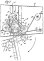
- a helicopter having a fuselage 10 terminating in an aft tail cone 12 and tail rotor pylon 14 which supports the tail rotor 16.
- a usual pilot's compartment 18 is provided in the forward end of the fuselage.
- a main rotor head 20 has four blades 22 which are foldable back over the fuselage as shown in these figures.
- Tail rotor pylon 14 which is an extension of the tapered tail cone 12 is mounted on a vertical hinge pin 24 on the end of the tail cone for folding movement into a position in which it lies alongside tail cone 12 as shown in these figures. With blades 22 folded and tail rotor pylon 14 folded, as shown, the helicopter can be stored in a shipboard hanger or transported in a carrier elevator for storage below deck.
- the blade pitch of tail rotor 16 is controlled by the pilot by means of cables and pulleys mounted in the tail cone and tail rotor pylon and in accordance with this invention an improved cable pulley and linkage mechanism 26 is provided at the junction between the tail cone and the tail rotor pylon for maintaining the cable at substantially constant tension during the folding and unfolding movements of the pylon.
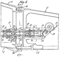
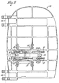
- This mechanism is shown most clearly in Figs. 3, 4 and 5.
- Fig. 4 and 5 there are two cable and pulley mechanisms shown, one above the other, forming the two halves of the cable system. Since they are identical, only one will be described in detail. For this purpose, reference is made particularly to Fig. 3.
- the improved cable control mechanism 26 for cable 28 consists of a pulley 30 fixed to pylon 14, a pulley 32 fixed to tail cone 12 and a free-floating pulley 34. All three pulleys 30, 32 and 34 are small and of the same diameter. Free-floating pulley 34 is supported by two links 36 and 38 of different length. The longer link 36 is pivoted on pylon 14 at 40 which is also the pivot for pulley 30. The shorter link 38 is pivoted at one end on the tail cone at 42. Links 36 and 38 have their free ends pivotally connected by pivot pin 44 which is also the pivot for floating pulley 34.
- Links 36 and 38 together with tail cone and pylon structure provide a 4-bar linkage, indicated on the drawings in dash lines, forming a quadrilateral figure having sides A, B, C and D no two of which are parallel.
- Side A consists of the portion of the tail cone 12 between fold hinge line 46 and pin 42;
- side B consists of link 38;
- side C consists of link 36; and
- side D consists of the portion of tail rotor pylon 14 between pin 40 and fold hinge line 46.
- Side A is sometimes referred to as the "ground bar” since it is the part of the basic structure which does not move relative to the other bars.
- pulley 32 is not mounted on pin 42 at the end of link 38, but instead is critically located on a pin well spaced forward of pin 42 on tail cone 12. Also it should be noted that link 38 between pivots 42 and 44 is shorter than link 36 between pivots 40 and 44 and that side D of the quadrilateral figure is longer than side A.
- Restraint member 49 having shoe 51 at one end is pivotally attached to link 38 by pin 53.
- Slot 57 allows member 49 to pivot on pin 53 during the folding cycle such that shoe 51 functions to restrain the cable in the unfolded pylon position, without adverse cable bending in the folded pylon position.
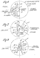
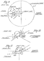
- Figs. 6, 7 and 8 the operation of this improved system of linkage and pulleys is illustrated diagrammatically, the flight position of the parts being shown in Fig. 6, the folded position of the pylon being shown in Fig. 8 and an intermediate position being shown in Fig. 7.
- These figures also show the envelope circle E which is the smallest circle within which the mechanism can be used.
- Fig. 6 shows the position of links and pulleys which determines the size of the envelope circle.
- Aircraft specification requirements dictate that, for the size of cable used, the pulleys must be at least 90 mm in diameter. Also they specify that no portion of the reach of the cable between two pulleys shall contact more than one pulley during tail rotor blade pitch control operation.
- the tail cone at the hinge line measures 380 mm in diameter in the helicopter shown.
- Figs. 9, 10 and 11 which are drawn to the same scale as Figs. 6, 7 and 8 demonstrate why the pulley and linkage system of the US Patent No. 3,901,464 does not anticipate the invention claimed herein.
- his parallelogram linkage shown in dash lines in Figs. 9 and 10
- his envelope circle is too big to allow the use of his linkage system for applicant's purposes.
Landscapes
- Engineering & Computer Science (AREA)
- Mechanical Engineering (AREA)
- Aviation & Aerospace Engineering (AREA)
- Electric Cable Installation (AREA)
- Toys (AREA)
- Laying Of Electric Cables Or Lines Outside (AREA)
- Catching Or Destruction (AREA)
- Medicines Containing Material From Animals Or Micro-Organisms (AREA)
- Inorganic Insulating Materials (AREA)
- Insulated Conductors (AREA)
- Ropes Or Cables (AREA)
- Turbine Rotor Nozzle Sealing (AREA)
- Flexible Shafts (AREA)
- Paper (AREA)
Claims (6)
Priority Applications (1)
| Application Number | Priority Date | Filing Date | Title |
|---|---|---|---|
| AT80900354T ATE3267T1 (de) | 1979-02-15 | 1980-01-21 | Vorrichtung zum einklappen eines hinteren rotor- kabelantriebs. |
Applications Claiming Priority (2)
| Application Number | Priority Date | Filing Date | Title |
|---|---|---|---|
| US12548 | 1979-02-15 | ||
| US06/012,548 US4245801A (en) | 1979-02-15 | 1979-02-15 | Tail rotor control cable-pylon fold accommodation |
Publications (3)
| Publication Number | Publication Date |
|---|---|
| EP0023909A1 EP0023909A1 (de) | 1981-02-18 |
| EP0023909A4 EP0023909A4 (de) | 1981-03-27 |
| EP0023909B1 true EP0023909B1 (de) | 1983-05-11 |
Family
ID=21755485
Family Applications (1)
| Application Number | Title | Priority Date | Filing Date |
|---|---|---|---|
| EP80900354A Expired EP0023909B1 (de) | 1979-02-15 | 1980-08-25 | Vorrichtung zum einklappen eines hinteren rotor-kabelantriebs |
Country Status (12)
| Country | Link |
|---|---|
| US (1) | US4245801A (de) |
| EP (1) | EP0023909B1 (de) |
| JP (1) | JPS55114696A (de) |
| AT (1) | ATE3267T1 (de) |
| AU (1) | AU526518B2 (de) |
| BE (1) | BE881633A (de) |
| CA (1) | CA1130770A (de) |
| DE (1) | DE3062998D1 (de) |
| DK (1) | DK427480A (de) |
| IT (1) | IT1140572B (de) |
| NO (1) | NO147177C (de) |
| WO (1) | WO1980001675A1 (de) |
Cited By (1)
| Publication number | Priority date | Publication date | Assignee | Title |
|---|---|---|---|---|
| RU208636U1 (ru) * | 2021-10-04 | 2021-12-28 | Общество с ограниченной ответственностью «РД-Хели» | Беспилотный винтокрылый летательный аппарат (бвла) |
Families Citing this family (14)
| Publication number | Priority date | Publication date | Assignee | Title |
|---|---|---|---|---|
| US5645249A (en) * | 1994-08-29 | 1997-07-08 | Mcdonnell Douglas Corporation | Helicopter stowable horizontal stabilizer |
| US20090283628A1 (en) * | 2008-05-19 | 2009-11-19 | Frederickson Kirk C | Directional control arrangement to provide stabilizing feedback to a structural bending mode |
| WO2011068445A1 (en) * | 2009-12-02 | 2011-06-09 | Saab Ab | Dismountable helicopter |
| CN101723091B (zh) * | 2009-12-16 | 2012-04-18 | 李游 | 旋翼直升机的旋翼变距控制装置 |
| GB2501145A (en) * | 2012-04-12 | 2013-10-16 | Supercell Oy | Rendering and modifying objects on a graphical user interface |
| CN102923302A (zh) * | 2012-11-12 | 2013-02-13 | 华南农业大学 | 一种直升机柔性连接旋转升力翼 |
| EP2933187B1 (de) * | 2014-04-15 | 2017-01-11 | AIRBUS HELICOPTERS DEUTSCHLAND GmbH | Drehflügelflugzeug mit einem mehrholmigen Heckausleger |
| CN105644778A (zh) * | 2014-11-14 | 2016-06-08 | 江西昌河航空工业有限公司 | 一种直升机应急辅助折叠和展开的方法 |
| FR3034397B1 (fr) * | 2015-03-31 | 2017-03-31 | Airbus Helicopters | Dispositif de repliage/depliage d'une poutre de queue d'un giravion, giravion associe et procede de repliage/depliage correspondant |
| CN104816820B (zh) * | 2015-05-08 | 2019-01-08 | 重庆大学 | 具有活动分角舰载直升机辅助折叠机构 |
| CN104802979B (zh) * | 2015-05-08 | 2017-04-19 | 重庆大学 | 具有固定分角的舰载直升机多连杆辅助折叠机构 |
| CN105799917B (zh) * | 2016-03-17 | 2019-11-19 | 中国直升机设计研究所 | 一种直升机旋翼桨叶系留方法及直升机旋翼桨叶系留装置 |
| CN107010197B (zh) * | 2016-11-22 | 2023-09-12 | 中国人民解放军空军工程大学 | 一种静止螺旋桨特定方向生成和固定机构 |
| CN107600386B (zh) * | 2017-10-18 | 2023-11-07 | 沈阳旋飞航空技术有限公司 | 电动无人机的悬臂 |
Family Cites Families (5)
| Publication number | Priority date | Publication date | Assignee | Title |
|---|---|---|---|---|
| US3116896A (en) * | 1961-04-05 | 1964-01-07 | Eltra Corp | Combination helicopter-automobile |
| US3142459A (en) * | 1963-03-07 | 1964-07-28 | Boeing Co | Aileron control on variable sweep wing designs |
| GB1316320A (en) * | 1970-12-18 | 1973-05-09 | Westland Aircraft Ltd | Rotary wing aircraft with folding rotor blades |
| GB1472540A (en) * | 1973-08-28 | 1977-05-04 | Westland Aircraft Ltd | Helicopters |
| US3901464A (en) * | 1974-11-08 | 1975-08-26 | Us Air Force | Flight control device |
-
1979
- 1979-02-15 US US06/012,548 patent/US4245801A/en not_active Expired - Lifetime
-
1980
- 1980-01-21 AT AT80900354T patent/ATE3267T1/de not_active IP Right Cessation
- 1980-01-21 WO PCT/US1980/000052 patent/WO1980001675A1/en not_active Ceased
- 1980-01-21 DE DE8080900354T patent/DE3062998D1/de not_active Expired
- 1980-01-25 CA CA344,362A patent/CA1130770A/en not_active Expired
- 1980-02-04 AU AU55176/80A patent/AU526518B2/en not_active Ceased
- 1980-02-08 BE BE0/199333A patent/BE881633A/fr not_active IP Right Cessation
- 1980-02-13 IT IT19872/80A patent/IT1140572B/it active
- 1980-02-14 JP JP1769980A patent/JPS55114696A/ja active Granted
- 1980-08-25 EP EP80900354A patent/EP0023909B1/de not_active Expired
- 1980-10-10 DK DK427480A patent/DK427480A/da not_active Application Discontinuation
- 1980-10-10 NO NO803025A patent/NO147177C/no unknown
Cited By (1)
| Publication number | Priority date | Publication date | Assignee | Title |
|---|---|---|---|---|
| RU208636U1 (ru) * | 2021-10-04 | 2021-12-28 | Общество с ограниченной ответственностью «РД-Хели» | Беспилотный винтокрылый летательный аппарат (бвла) |
Also Published As
| Publication number | Publication date |
|---|---|
| IT1140572B (it) | 1986-10-01 |
| JPH0127920B2 (de) | 1989-05-31 |
| NO147177C (no) | 1983-02-16 |
| NO803025L (no) | 1980-10-10 |
| US4245801A (en) | 1981-01-20 |
| CA1130770A (en) | 1982-08-31 |
| AU526518B2 (en) | 1983-01-13 |
| ATE3267T1 (de) | 1983-05-15 |
| DE3062998D1 (en) | 1983-06-16 |
| JPS55114696A (en) | 1980-09-04 |
| BE881633A (fr) | 1980-05-30 |
| EP0023909A1 (de) | 1981-02-18 |
| AU5517680A (en) | 1980-08-21 |
| NO147177B (no) | 1982-11-08 |
| IT8019872A0 (it) | 1980-02-13 |
| DK427480A (da) | 1980-10-10 |
| EP0023909A4 (de) | 1981-03-27 |
| WO1980001675A1 (en) | 1980-08-21 |
Similar Documents
| Publication | Publication Date | Title |
|---|---|---|
| EP0023909B1 (de) | Vorrichtung zum einklappen eines hinteren rotor-kabelantriebs | |
| US5836550A (en) | Mechanism for streamwise fowler deployment of the wing trailing or leading edge | |
| US4336914A (en) | Deployable wing mechanism | |
| US4202519A (en) | Airfoil leading edge slat apparatus | |
| US2859002A (en) | Airfoil aircraft interconnecting boom | |
| CA1113070A (en) | Deployable wing mechanism | |
| US4106727A (en) | Aircraft folding airfoil system | |
| US5158252A (en) | Three-position variable camber Krueger leading edge flap | |
| US4669687A (en) | Airfoil flap member with flap track member | |
| US4424945A (en) | Parafoil | |
| US4776537A (en) | Fuel storage means | |
| US4405105A (en) | Airfoil flap actuation | |
| US5645249A (en) | Helicopter stowable horizontal stabilizer | |
| RU2002124855A (ru) | Летательный аппарат | |
| WO2008125868A2 (en) | Aircraft | |
| US4000868A (en) | Deflector blade of variable camber | |
| US3097701A (en) | Blade folding mechanism | |
| EP4026769A1 (de) | Fahrwerkstürsystem für einen fahrwerksraum | |
| GB2276131A (en) | Variable camber vane | |
| US2538602A (en) | Aircraft control mechanism | |
| US3765622A (en) | Aircraft control means | |
| JPH02504622A (ja) | 特に帆船用のマスト | |
| US2925130A (en) | Means of folding rotor blades | |
| GB2079688A (en) | Aircraft fitted with wing trailing edge flaps actuated by six-bar mechanisms. | |
| US3369780A (en) | Aircraft having flexible wing surfaces |
Legal Events
| Date | Code | Title | Description |
|---|---|---|---|
| PUAI | Public reference made under article 153(3) epc to a published international application that has entered the european phase |
Free format text: ORIGINAL CODE: 0009012 |
|
| AK | Designated contracting states |
Designated state(s): AT CH DE FR GB NL SE |
|
| 17P | Request for examination filed |
Effective date: 19810107 |
|
| GRAA | (expected) grant |
Free format text: ORIGINAL CODE: 0009210 |
|
| AK | Designated contracting states |
Designated state(s): AT CH DE FR GB NL SE |
|
| REF | Corresponds to: |
Ref document number: 3267 Country of ref document: AT Date of ref document: 19830515 Kind code of ref document: T |
|
| REF | Corresponds to: |
Ref document number: 3062998 Country of ref document: DE Date of ref document: 19830616 |
|
| ET | Fr: translation filed | ||
| PGFP | Annual fee paid to national office [announced via postgrant information from national office to epo] |
Ref country code: CH Payment date: 19831216 Year of fee payment: 5 |
|
| PLBE | No opposition filed within time limit |
Free format text: ORIGINAL CODE: 0009261 |
|
| STAA | Information on the status of an ep patent application or granted ep patent |
Free format text: STATUS: NO OPPOSITION FILED WITHIN TIME LIMIT |
|
| 26N | No opposition filed | ||
| PGFP | Annual fee paid to national office [announced via postgrant information from national office to epo] |
Ref country code: FR Payment date: 19841210 Year of fee payment: 6 Ref country code: AT Payment date: 19841210 Year of fee payment: 6 |
|
| PGFP | Annual fee paid to national office [announced via postgrant information from national office to epo] |
Ref country code: NL Payment date: 19841217 Year of fee payment: 6 |
|
| PGFP | Annual fee paid to national office [announced via postgrant information from national office to epo] |
Ref country code: SE Payment date: 19841231 Year of fee payment: 6 |
|
| PG25 | Lapsed in a contracting state [announced via postgrant information from national office to epo] |
Ref country code: AT Effective date: 19860121 |
|
| PG25 | Lapsed in a contracting state [announced via postgrant information from national office to epo] |
Ref country code: SE Effective date: 19860122 |
|
| PG25 | Lapsed in a contracting state [announced via postgrant information from national office to epo] |
Ref country code: CH Effective date: 19860131 |
|
| PG25 | Lapsed in a contracting state [announced via postgrant information from national office to epo] |
Ref country code: NL Effective date: 19860801 |
|
| NLV4 | Nl: lapsed or anulled due to non-payment of the annual fee | ||
| PG25 | Lapsed in a contracting state [announced via postgrant information from national office to epo] |
Ref country code: FR Free format text: LAPSE BECAUSE OF NON-PAYMENT OF DUE FEES Effective date: 19860930 |
|
| REG | Reference to a national code |
Ref country code: CH Ref legal event code: PL |
|
| REG | Reference to a national code |
Ref country code: FR Ref legal event code: ST |
|
| EUG | Se: european patent has lapsed |
Ref document number: 80900354.4 Effective date: 19861028 |
|
| PGFP | Annual fee paid to national office [announced via postgrant information from national office to epo] |
Ref country code: DE Payment date: 19961218 Year of fee payment: 18 |
|
| PGFP | Annual fee paid to national office [announced via postgrant information from national office to epo] |
Ref country code: GB Payment date: 19961219 Year of fee payment: 18 |
|
| PG25 | Lapsed in a contracting state [announced via postgrant information from national office to epo] |
Ref country code: GB Free format text: LAPSE BECAUSE OF NON-PAYMENT OF DUE FEES Effective date: 19980121 |
|
| GBPC | Gb: european patent ceased through non-payment of renewal fee |
Effective date: 19980121 |
|
| PG25 | Lapsed in a contracting state [announced via postgrant information from national office to epo] |
Ref country code: DE Free format text: LAPSE BECAUSE OF NON-PAYMENT OF DUE FEES Effective date: 19981001 |