EP2933187B1 - Drehflügelflugzeug mit einem mehrholmigen Heckausleger - Google Patents
Drehflügelflugzeug mit einem mehrholmigen Heckausleger Download PDFInfo
- Publication number
- EP2933187B1 EP2933187B1 EP14400026.2A EP14400026A EP2933187B1 EP 2933187 B1 EP2933187 B1 EP 2933187B1 EP 14400026 A EP14400026 A EP 14400026A EP 2933187 B1 EP2933187 B1 EP 2933187B1
- Authority
- EP
- European Patent Office
- Prior art keywords
- tail
- boom
- elements
- fuselage
- rotary wing
- Prior art date
- Legal status (The legal status is an assumption and is not a legal conclusion. Google has not performed a legal analysis and makes no representation as to the accuracy of the status listed.)
- Not-in-force
Links
- 230000007935 neutral effect Effects 0.000 claims description 5
- 238000013461 design Methods 0.000 description 22
- 238000005452 bending Methods 0.000 description 18
- 230000005540 biological transmission Effects 0.000 description 8
- 238000010276 construction Methods 0.000 description 7
- 230000010354 integration Effects 0.000 description 7
- 230000009471 action Effects 0.000 description 5
- 230000008878 coupling Effects 0.000 description 5
- 238000010168 coupling process Methods 0.000 description 5
- 238000005859 coupling reaction Methods 0.000 description 5
- 238000012546 transfer Methods 0.000 description 4
- 230000000694 effects Effects 0.000 description 3
- 230000003601 intercostal effect Effects 0.000 description 3
- 230000000873 masking effect Effects 0.000 description 3
- 239000000463 material Substances 0.000 description 3
- 230000009467 reduction Effects 0.000 description 3
- 230000000712 assembly Effects 0.000 description 2
- 238000000429 assembly Methods 0.000 description 2
- 230000008901 benefit Effects 0.000 description 2
- 238000006243 chemical reaction Methods 0.000 description 2
- 239000007789 gas Substances 0.000 description 2
- 230000005484 gravity Effects 0.000 description 2
- 238000007689 inspection Methods 0.000 description 2
- 238000012423 maintenance Methods 0.000 description 2
- 238000004519 manufacturing process Methods 0.000 description 2
- 238000000034 method Methods 0.000 description 2
- 230000008569 process Effects 0.000 description 2
- 239000000243 solution Substances 0.000 description 2
- 230000007704 transition Effects 0.000 description 2
- 238000013459 approach Methods 0.000 description 1
- 239000002131 composite material Substances 0.000 description 1
- 150000001875 compounds Chemical class 0.000 description 1
- 238000002347 injection Methods 0.000 description 1
- 239000007924 injection Substances 0.000 description 1
- 238000009434 installation Methods 0.000 description 1
- 230000003993 interaction Effects 0.000 description 1
- 230000009347 mechanical transmission Effects 0.000 description 1
- 230000001141 propulsive effect Effects 0.000 description 1
- 230000000087 stabilizing effect Effects 0.000 description 1
- 230000003068 static effect Effects 0.000 description 1
- 230000032258 transport Effects 0.000 description 1
Images


Classifications
-
- B—PERFORMING OPERATIONS; TRANSPORTING
- B64—AIRCRAFT; AVIATION; COSMONAUTICS
- B64C—AEROPLANES; HELICOPTERS
- B64C1/00—Fuselages; Constructional features common to fuselages, wings, stabilising surfaces or the like
- B64C1/06—Frames; Stringers; Longerons ; Fuselage sections
- B64C1/061—Frames
- B64C1/063—Folding or collapsing to reduce overall dimensions, e.g. foldable tail booms
-
- B—PERFORMING OPERATIONS; TRANSPORTING
- B64—AIRCRAFT; AVIATION; COSMONAUTICS
- B64C—AEROPLANES; HELICOPTERS
- B64C1/00—Fuselages; Constructional features common to fuselages, wings, stabilising surfaces or the like
- B64C1/26—Attaching the wing or tail units or stabilising surfaces
-
- B—PERFORMING OPERATIONS; TRANSPORTING
- B64—AIRCRAFT; AVIATION; COSMONAUTICS
- B64C—AEROPLANES; HELICOPTERS
- B64C27/00—Rotorcraft; Rotors peculiar thereto
- B64C27/82—Rotorcraft; Rotors peculiar thereto characterised by the provision of an auxiliary rotor or fluid-jet device for counter-balancing lifting rotor torque or changing direction of rotorcraft
- B64C2027/8209—Electrically driven tail rotors
-
- B—PERFORMING OPERATIONS; TRANSPORTING
- B64—AIRCRAFT; AVIATION; COSMONAUTICS
- B64C—AEROPLANES; HELICOPTERS
- B64C27/00—Rotorcraft; Rotors peculiar thereto
- B64C27/82—Rotorcraft; Rotors peculiar thereto characterised by the provision of an auxiliary rotor or fluid-jet device for counter-balancing lifting rotor torque or changing direction of rotorcraft
- B64C2027/8254—Shrouded tail rotors, e.g. "Fenestron" fans
-
- B—PERFORMING OPERATIONS; TRANSPORTING
- B64—AIRCRAFT; AVIATION; COSMONAUTICS
- B64C—AEROPLANES; HELICOPTERS
- B64C27/00—Rotorcraft; Rotors peculiar thereto
- B64C27/82—Rotorcraft; Rotors peculiar thereto characterised by the provision of an auxiliary rotor or fluid-jet device for counter-balancing lifting rotor torque or changing direction of rotorcraft
- B64C2027/8263—Rotorcraft; Rotors peculiar thereto characterised by the provision of an auxiliary rotor or fluid-jet device for counter-balancing lifting rotor torque or changing direction of rotorcraft comprising in addition rudders, tails, fins, or the like
Definitions
- the invention relates to a rotary wing aircraft with a tail supporting a tail rotor, possibly at least one tail rotor being an electrically driven tail rotor.
- the dominant rotary wing aircraft configuration in the present time is based on helicopter basic design including a single main rotor and an auxiliary tail rotor to counter torque and provide directional yaw control.
- the tail rotor is mounted at the rear end of a supporting structure - the tail boom - behind the main fuselage. This tail boom is typically a single beam element.
- a fin arranged at the same location as the tail rotor provides for directional stability during forward flight hence relieving the tail rotor and reducing the power needed for anti-torque.
- One or more horizontal tail planes are arranged as well at the aft portion of the tail boom or on top of the fin in order to provide for pitch stability.
- the large lever arm between the center of gravity and the tail rotor improves the efficiency of the active and passive stabilizing system and reduces the interaction with the main rotor.
- the root attachment of a centrally arranged tail boom is allocated on an upper part of the fuselage, which leads, on the one hand, to a reduction of cabin volume and loading clearance.
- the root attachment sets important requirements on the front root structure of the tail boom in terms of fire resistance due to its integration within the engine deck area of the helicopter, leading to a higher structural complexity and the use of expensive materials and complex interface joints.
- Typical tail booms are impacted by the hot exhaust gases of the helicopter's engines, especially during hover, setting important requirements to the choice of structural materials in terms of their heat resistance which translates to less design flexibility and larger material costs.
- the disassembly of a typical continuous circumferential joint of a single tail boom beam element with a large amount of fasteners from a fuselage or the integration of pivotable features between a single tail boom beam element and a fuselage is complex.
- the integration of pivotable features within conventional tail booms is inefficient since it does not allow large folding angles relative to a fuselage due to the central arrangement of the tail booms with cross-sections widths considerably smaller than the width of the fuselage.
- Integrated tail booms shaped as a smooth continuation of the fuselage hull lead to reductions in drag during forward flight but, on contrary, to an increase of down-load in the hover.
- a streamlined tail boom may be practical on executive transports, but for other purposes rear loading ramps or clamshell doors may be needed which result in typical pod and boom designs with higher drag during forward flight.
- the integration of pivotable or dismountable streamlined tail booms lead moreover to a considerable structural weight increase and to less efficient folding characteristics.
- a typical cylindrical shape of a tail boom is optimal for torsional stiffness but it is generally less efficient when subjected to a transverse flow.
- the unstable characteristics of a transverse airflow across a cylindrical shape are a possible source of shaking in the hover of the helicopter, which is a phenomenon directly linked to the bending stiffness of the tail boom.
- the tail boom houses the transmission and controls of the tail rotor, antennae and other systems, i.e. on-board equipment (e.g. electric, mechanical, electronic, tactical, etc.). Transmission shafts are typically arranged outside and on top of the load carrying tail boom structure to allow for easy inspection and maintenance.
- on-board equipment e.g. electric, mechanical, electronic, tactical, etc.
- a tail boom structure has to be designed according to static, dynamic and fatigue requirements, hence showing a certain bending and torsional stiffness, an adequate strength and an appropriate mass.
- the first typical tail boom is a single, slim beam element which is attached on its front end to the fuselage aft and top region.
- the typical cross-section of those tail booms is essentially cylindrical with a flat top or bottom base.
- the second type of tail boom is one single boom integrated within the fuselage body with a smoothly tapered transition from the central fuselage body to the tail.
- the cross section is however larger than that of the first design hence leading to increased down-loads generated by the down-wash of the main rotor.
- twin boom configurations are seldom and have been especially suggested for high speed rotorcraft configurations, the twin booms being typically parallel and attached at their rear end to the tips of a transverse tail plane.
- Some rotary wing aircrafts are designed with foldable capabilities so as to reduce their overall dimensions to facilitate stowage in confined available spaces. Typical folding capabilities are limited to the folding of the blades rearwardly and the folding of a rear portion of the tail forwardly.
- the document GB2359533 discloses a dismountable helicopter with a modular airframe and rotor unit.
- the torque compensating rotor in the tail of the helicopter is driven by a thin-walled drive shaft, detachably connected to the main power drive.
- the document GB2449743 describes an aircraft which can be dismounted into different parts; inter alia its rear part is entirely separable from the front part of the aircraft.
- the document US6050521 discloses a releasable coupling for a power transmission to a tail rotor of a foldable-tail- section helicopter.
- the coupling consists of two coupling assemblies, one associated with the front section of the helicopter, the other one associated with the tail section of the helicopter.
- the two coupling assemblies are coupled via radial toothings, cooperating telescopically with each other.
- the document US3921938 A shows a typical cantilever tail boom but with an asymmetrical arrangement with respect to the aircraft's longitudinal axis.
- the tail boom is pivotable about its front attachment to the fuselage. This arrangement allows for folding capabilities and a minimum stowage volume.
- the document US20120280079 shows a special design of a typical cantilevered tail boom with a streamlined cross-section of the tail boom in order to generate an anti-torque force by the effect of the downwash from the rotor.
- the document US2973923 describes a helicopter construction having a cabin and a main body that includes cabin framework as well as a tail for a counter torque rotor.
- the main body is formed of welded tubular metallic members, suitably cross braced.
- the main body is box shaped in cross-section, having no appreciable depth throughout.
- the main body has supports that carry a pair of motors for pivoting four rotor blades.
- the document EP2690010 describes a compound helicopter with a pair of tail booms and a pair of fixed main wings and a pair of additional propulsive devices, for lift and thrust during forward cruise flight.
- the document DE102011010097 describes a remote controlled model helicopter.
- Two receiver items are releasably connected to side plates of a helicopter frame.
- the helicopter frame is manufactured as an injection molded component.
- a tail boom mount is disposed at the level of a tail pulley so that a rear strap may be passed through a tail boom for a tail rotor.
- Under the tail boom two struts support the tail boom and are attached to the helicopter frame.
- the document DE202010014056 describes a radio controlled model helicopter.
- a rear fairing has side plates extending from the body to the tail of the model helicopter.
- the rear fairing has an open design for airflow through the cell and the tail boom in the direction of the rotor axis.
- the rear fairing has an integrated side plates fin.
- the rear fairing has for support of a stern tube, located fixings that give the side panels lift and shape.
- the rear fairing has a fastening on a chassis of the model helicopter to produce a self-supporting structure.
- a rotary wing aircraft is provided with a longitudinal axis in x-direction and comprises a fuselage forwardly oriented relative to the longitudinal axis with a port side and a starboard side as lateral sides.
- a main rotor is arranged above the fuselage and an anti-torque rotor is mounted on a tail.
- a tail boom is attached to a rearward oriented part of the fuselage.
- the tail boom is provided with at least two beam boom elements. At least one of the two beam boom elements extends from the port side and at least another one of the two beam boom elements extends from the starboard side of the fuselage to said rear end.
- a front tail boom beam element root of each of the at least two beam boom elements is respectively attached to the corresponding lateral side of the fuselage by a front attachment being a simply supported hinge connection and each of the at least two beam boom elements are canted with respect to the longitudinal axis and interconnected to each other at the rear end of said tail boom.
- At least one of the front attachments is releasable and at least another of the front attachments is pivotable so that the tail boom is pivotable about a z-direction, around at least one of the front attachments.
- front attachments of the respective tail boom beam element roots of each of the at least two beam boom elements at the fuselage are simply supported hinged connections.
- each of the at least two beam boom elements has a height-to-width ratio of at least three.
- each of the at least two beam boom elements has four or less but preferably not less than two securing bolts.
- the number of securing bolts for each of the beam boom elements is chosen among: two, three, four.
- the two front attachments of the at least two beam boom elements are releasable.
- one of the at least two beam boom elements is interconnected to another one of the at least two beam boom elements at its rear end by means of a simply supported hinged connection.
- the hinged rear connection has four or less but preferably not less than two bolts.
- one of the at least two beam boom elements is pivotable with respect to another one of the at least two beam boom elements about the rear hinged connection.
- each of the at least two beam boom elements has an airfoil shape so as to produce an anti-torque lifting force as a result from the down-wash flow.
- a gap is transversally provided between the two tail boom beam elements and this air gap has a transverse dimension that is comprised between an upright height dimension in cross section of the tail boom beam elements and five times this upright height dimension at the root of the tail boom beam elements.
- outer shapes of the at least two beam boom elements are an aerodynamic continuation of the hull of the fuselage.
- the tail boom comprise at least an electrically powered rotor drive.
- electrically powered tail rotor drives are provided.
- the introduction of electrically powered rotor drives opens new design possibilities of the tail boom due to the lack of mechanical force dynamic transmission shafts.
- the replacement of tail rotor shafts and gearboxes with electrical power transfer and rotor drives is deemed a possible future option in order to improve performance, reliability, safety and maintainability for rotary wing aircrafts, e.g. of the light tonnage category.
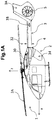
- a known rotary wing aircraft 1 of the helicopter type comprises a fuselage 2 and a single central tail boom 3 in conventional cantilever configuration mounted to a rear part of said fuselage 2.
- a main rotor 2A is mounted to a top deck of the fuselage 2.
- the single central tail boom 3 comprises a fin 3A and one or a plurality of horizontal planes 3B, at the very aft end of the tail boom.
- the single central tail boom 3 has a height 32 and a width 31 and it is attached to the rear part of the fuselage 2 at a tail boom root 4.
- the rear part of said fuselage 2 is provided with a rear access door 34.
- the fin 3A is generally vertical, is attached to a rear end of the tail boom 3 and houses a tail rotor 5 (here of Fenestron ⁇ type).
- the width 31 of the tail boom 3 is considerably less than a fuselage width 33.
- Engines 30 for driving the rotors 2A, 5 are allocated in an engine deck of the rear part of said fuselage 2.
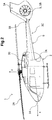
- FIGS 2-7 illustrate embodiments of the invention.
- corresponding features are referred to with the same references than the ones of Figure 1 .
- a rotary wing aircraft 1 according to the invention is provided with a front part 14 in an x-direction (longitudinal direction X).
- an inventive tail 3C includes tail boom beam elements 6A, 6B that are attached respectively to the port side and starboard side of the fuselage 2, longitudinally ahead of the rear part of the fuselage 2 in x-direction at respective lateral tail boom beam element roots 7A, 7B below the engine deck and the engines 30.
- the tail boom beam elements 6A, 6B belongs to the multi beam tail 3C - having at least one fin 3A and one tail rotor 5 - which makes the inventive tail 3C distinct from the prior art tail boom 3 of figure 1 .
- the tail boom beam elements 6A, 6B are straight lined, i.e. the tail beam boom elements 6A, 6B extend in straight line until the transition from the fuselage 2 to the vertical fin tail 3A.
- the port side beam element 6A and the starboard side beam element 6B of the inventive tail 3C provide a framework-type construction for the support of tail 3C.
- the two beam elements 6A and 6B of figures 7 are arranged separately in a y-direction to lateral sides 29 of the fuselage 2 of the rotary wing aircraft 1 with respect to the longitudinal x-direction fuselage at their respective tail boom beam element roots 7A and 7B.
- the port side beam element 6A and the starboard side beam element 6B have a distance between each other at their respective tail boom beam element roots 7A and 7B corresponding to almost the entire width of the fuselage 2 in y-direction (transverse direction Y).
- the port side beam element 6A and the starboard side beam element 6B are arranged symmetrically to the longitudinal x-direction of the rotary wing aircraft 1, while the respective shapes of their cross sections in an x-z plane shall not necessarily be symmetrical to the x-direction. None of the tail boom beam elements 6A and 6B are directly attached to a center portion of the rear part of the fuselage 2, hence offering a large, undisturbed rear part area for large access doors to the fuselage 2.
- the port side beam element 6A and the starboard side beam element 6B are designed as smooth continuation of the hull of the fuselage 2 and the tail boom beam roots 7A and 7B are away from, i.e. below, the engine deck at an upper part of the fuselage 2 and the engines 30.
- the port side beam element 6A and the starboard side beam element 6B are canted for interconnection to each other at their rear portion of the tail 3C towards the fin 3A.
- the rotor 5 shall be an electrically powered tail rotor 5B, thus making useless the mechanical force power transmission between the fuselage 2 and the tail rotor 5B.
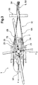
- the port side boom beam element 6A and the starboard side beam element 6B of the rotary wing aircraft 1 feature a main load carrying box 9 confined between two main spars 12 and sheathed by a skin (not shown).
- a skin not shown
- the spars 12 of the port side boom beam element 6A are attached at the corresponding tail boom beam root 7A at two attachment points 13A separate in z-direction.
- Each attachment point 13A is a releasable single-bolt-joint.
- the attachment points 13A are connected to a rear frame 8 with two corresponding intercostals 15 supported by said frame 8 in the fuselage 2.
- a hinged connection 20 At the rear end of the port side boom beam element 6A is a hinged connection 20 with a minimum of two bolts separate in z-direction.
- the starboard side boom beam element 6B and its connection to the fuselage 2 are structurally similar to the ones for the port side boom beam element 6A, including the attachment points 13A and starboard side attachment points 13B.
- the hinged connection 20 of the port side boom beam element 6A interconnects the port side boom beam element 6A to the starboard side boom beam element 6B at their rear ends next to the fin 3A.
- the tail boom beam elements 6A, 6B are tapered along their length 22, with the larger height at the tail boom beam roots 7A, 7B.
- a frame-work type construction 16 composed of two truss elements 17A and 17B corresponds to the tail boom beam elements 6A and 6B in the x-y plane.
- the truss elements represent the neutral lines of both tail boom beam elements.
- the truss elements 17A and 17B are supported at the fuselage 2 at the attachment points 13A and 13B.
- the port side boom beam element 6A is interconnected to the starboard boom beam element 6B at the hinged connection 20.
- the lines of action of the truss elements 17A, 7B are canted in the x-y plane to intersect each other at an intersection point 18.
- the transverse anti-torque force 19 provided by the tail 5 is in line with said intersection point 18.
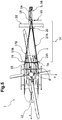
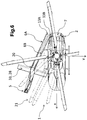
- the rotary wing aircraft 1 is in its folded configuration ready for stowage, the elements 6A, 6B being pivoted against the fuselage 2 at the point 13B.
- Rotor blades 21 (dashed lines) of the main rotor 2A are folded in x-direction forwardly about their root hinges to a stowed position in a front part of the fuselage 2.
- the tail boom beam elements 6A, 6B are folded forwardly about the z-direction through the hinged attachment point 13B to a position alongside the starboard side of the rotary wing aircraft 1.
- the tail boom beam element 6A is folded about the hinged connection 20, against the other element 6B.
- a T-tail (not shown) with an upper tail plane 28, e.g. horizontal, installed atop the fin 3A and above the rotor would allow the tail beam boom elements 6A, 6B to further rotate about the attachment point 13B to be aligned to the rotary wing aircraft's 1 x-direction and would hence reduce the compact stowage volume of the rotary wing aircraft 1 to a minimum.
- the inventive tail 3C is laterally rotatable, so as to be folded sideward against the fuselage, by at least one upwards hinged attachment connection between the respective front end of one of the beam boom elements 6A or 6B and the fuselage 2.
- the two beam boom elements 6A, 6B are pivoted around a rear end upward hinge connection, for compacting the volume of the tail 3C from the operational "V" shaped position as seen on Figure 5 , to the compact position of the beam boom element 6A, 6B as seen on Figure 6 , where the beam boom element 6A, 6B are slightly parallel one to the other.
- an exemplary cross-section 26 in a y-z plane of the tail boom beam elements 6A, 6B is located among the inventive tail 3C, close to the fuselage 2 and the points 13A-B.
- the cross-section 26 has a width 24, i.e. an extension in y-direction, generally considerably less than its height 23, extension in z-direction, namely a height-to-width ratio of at least three (3).
- the upwards dimension is here at minimum three times larger than the corresponding transverse dimension in a given cross-section of the beam boom element.
- the cross-section's airfoil shape and orientation are arranged in order to support the anti-torque force 19 and to minimize the drag generated by the down wash air flow 25.
- FIG. 7 On Figure 7 is shown an air gap G that is transversally provided between the two tail boom beam elements 6A, 6B.
- This air gap G has a transverse dimension GY.
- the maximal dimension GY transversally between both boom elements 6A-6B at their roots close to the fuselage 2 is e.g. in the range of one to five times the height of the upwards cross section of the boom elements 6A-6B at their root.
- the maximal transverse dimension GY is measured at the very rear end of the tail 3C, while there is actually a rearmost gap close to the fin 3A which is almost zero.
Claims (14)
- Drehflügelflugzeug (1) mit einer Längsachse in x-Richtung, welches mindestens aufweist:- einen relativ zu der Längsachse nach vorne ausgerichteten Rumpf (2) mit einer Backbordseite und einer Steuerbordseite als seitlichen Seiten,- einen Hauptrotor (2A), der über dem Rumpf (2) angeordnet ist,- einen Heckrotor (5), der an einem Heck (3C) montiert ist, wobei das Heck (3C) an dem nach hinten ausgerichteten Teil des Rumpfes (2) befestigt ist, wobei das Heck (3C) ein hinteres Ende aufweist, welches den Heckrotor (5) trägt, und- mindestens einen Motor (30) zum Antreiben des mindestens einen Rotors (2A, 5), wobei der Motor (30) am Rumpf (2) montiert ist, wobei das Heck (3C) mit zwei Trägerauslegerelementen (6A, 6B) versehen ist, die sich zu dem hinteren Ende des Rumpfes (2) erstrecken, wobei eines der beiden Trägerauslegerelemente (6A, 6B) sich von der Backbordseite und das andere Trägerauslegerelement (6B, 6A) sich von der Steuerbordseite aus erstreckt, wobei ein vorderer Heckauslegerträgerelementfuß (7A, 7B) eines jeden der beiden Trägerauslegerelemente (6A, 6B) jeweils an der zugehörigen Backbord-/Steuerbordseite des Rumpfes (2) durch eine Frontbefestigung (13A, 13B) befestigt ist,
dadurch gekennzeichnet, dass
die Trägerauslegerelemente (6A, 6B) bezüglich der Längsachse schräg ausgerichtet sind und am hinteren Ende des Hecks (3C) miteinander verbunden sind, und wobei mindestens eine der Frontbefestigungen (13A, 13B) lösbar und mindestens eine andere der Frontbefestigungen (13B, 13A) schwenkbar ist, sodass das Heck (3C) um eine z-Richtung um mindestens eine der Frontbefestigungen (13B, 13A) schwenkbar ist. - Drehflügelflugzeug (1) nach Anspruch 1, wobei die Frontbefestigungen (13A, 13B) der jeweiligen Heckauslegerträgerelementfüße (7A, 7B) eines jeden der beiden Trägerauslegerelemente (6A, 6B) an dem Rumpf (2) einfach durch Gelenkverbindungen getragen werden.
- Drehflügelflugzeug (1) nach Anspruch 1, wobei der Querschnitt eines jeden der beiden Trägerauslegerelemente (6A, 6B) ein Höhezu-Breite-Verhältnis von wenigstens drei aufweist.
- Drehflügelflugzeug (1) nach Anspruch 2, wobei die Frontbefestigungen (13A, 13B) Befestigungsbolzen aufweisen, wobei eine Anzahl von Befestigungsbolzen eines jeden der beiden Trägerauslegerelemente (6A, 6B) ausgewählt ist aus: zwei, drei oder vier Befestigungsbolzen.
- Drehflügelflugzeug (1) nach Anspruch 1, wobei die Frontbefestigungen (13A, 13B) lösbar sind.
- Drehflügelflugzeug (1) nach Anspruch 1, wobei jedes der beiden Trägerauslegerelemente (6A, 6B) mit dem anderen an dessen hinterem Ende durch eine gelagerte Gelenkverbindung (20) verbunden ist.
- Drehflügelflugzeug (1) nach Anspruch 6, wobei jede Gelenkverbindung (20) Befestigungsbolzen aufweist, wobei eine Anzahl von Befestigungsbolzen ausgewählt ist aus: zwei, drei oder vier Befestigungsbolzen.
- Drehflügelflugzeug (1) nach Anspruch 6, wobei eines der Trägerauslegerelemente (6A, 6B) an den hinteren Enden der beiden Trägerauslegerelemente (6A, 6B) relativ zu dem anderen um die Gelenkverbindung (20) schwenkbar ist.
- Drehflügelflugzeug (1) nach einem der Ansprüche 1 bis 8, wobei ein Luftspalt (G) in Querrichtung zwischen den beiden Trägerauslegerelementen (6A, 6B) vorgesehen ist, wobei der Luftspalt (G) eine Querabmessung (GY) aufweist, die zwischen einer vertikalen Höhenabmessung (23) im Querschnitt der Heckträgerauslegerelemente (6A, 6B) und dem Fünffachen dieser vertikalen Höhenabmessung (23) liegt.
- Drehflügelflugzeug (1) nach einem der Ansprüche 6 bis 8, wobei die Trägerauslegerelemente (6A, 6B) jeweils eine neutrale Linie aufweisen, die zwischen dem vorderen Heckauslegerträgerelementfuß und der hinteren Gelenkverbindung (20) geradlinig ist.
- Drehflügelflugzeug (1) nach Anspruch 1, wobei mindestens eines der Trägerauslegerelemente (6A, 6B) von der Frontbefestigung (13A, 13B) bis zu dem hinteren Ende vollkommen geradlinig ausgelegt ist.
- Drehflügelflugzeug (1) nach Anspruch 1, wobei der Querschnitt eines jeden der Trägerauslegerelemente (6A, 6B) eine Tragflächenform aufweist, um eine drehmomentausgleichende Auftriebskraft zu erzeugen als ein Ergebnis der Abwindströmung von dem Hauptrotor (2A).
- Drehflügelflugzeug (1) nach Anspruch 1, wobei der Rumpf eine Hülle aufweist, wobei die Trägerauslegerelemente (6A, 6B) äußere seitliche Formen aufweisen, die eine aerodynamische Fortsetzung der Hülle des Rumpfes (2) bilden.
- Drehflügelflugzeug (1) nach Anspruch 1, wobei das Drehflügelflugzeug (1) mindestens einen elektrisch gespeisten Rotorantrieb (D) für einen elektrisch gespeisten Heckrotor (5B) aufweist.
Priority Applications (2)
| Application Number | Priority Date | Filing Date | Title |
|---|---|---|---|
| EP14400026.2A EP2933187B1 (de) | 2014-04-15 | 2014-04-15 | Drehflügelflugzeug mit einem mehrholmigen Heckausleger |
| US14/679,072 US9592899B2 (en) | 2014-04-15 | 2015-04-06 | Rotary wing aircraft with a multiple beam tail |
Applications Claiming Priority (1)
| Application Number | Priority Date | Filing Date | Title |
|---|---|---|---|
| EP14400026.2A EP2933187B1 (de) | 2014-04-15 | 2014-04-15 | Drehflügelflugzeug mit einem mehrholmigen Heckausleger |
Publications (2)
| Publication Number | Publication Date |
|---|---|
| EP2933187A1 EP2933187A1 (de) | 2015-10-21 |
| EP2933187B1 true EP2933187B1 (de) | 2017-01-11 |
Family
ID=51167835
Family Applications (1)
| Application Number | Title | Priority Date | Filing Date |
|---|---|---|---|
| EP14400026.2A Not-in-force EP2933187B1 (de) | 2014-04-15 | 2014-04-15 | Drehflügelflugzeug mit einem mehrholmigen Heckausleger |
Country Status (2)
| Country | Link |
|---|---|
| US (1) | US9592899B2 (de) |
| EP (1) | EP2933187B1 (de) |
Families Citing this family (13)
| Publication number | Priority date | Publication date | Assignee | Title |
|---|---|---|---|---|
| US10703471B2 (en) | 2016-06-03 | 2020-07-07 | Bell Helicopter Textron Inc. | Anti-torque control using matrix of fixed blade pitch motor modules |
| US10377479B2 (en) | 2016-06-03 | 2019-08-13 | Bell Helicopter Textron Inc. | Variable directional thrust for helicopter tail anti-torque system |
| US10526085B2 (en) | 2016-06-03 | 2020-01-07 | Bell Textron Inc. | Electric distributed propulsion anti-torque redundant power and control system |
| AU2018266343B2 (en) * | 2017-05-08 | 2023-09-21 | Insitu, Inc. | Modular aircraft with vertical takeoff and landing capability |
| US10611460B2 (en) * | 2017-05-11 | 2020-04-07 | Bell Helicopter Textron Inc. | Aircraft vertical stabilizer design |
| US10518865B2 (en) | 2017-05-11 | 2019-12-31 | Bell Helicopter Textron Inc. | Aircraft horizontal stabilizer design |
| US11186185B2 (en) | 2017-05-31 | 2021-11-30 | Textron Innovations Inc. | Rotor brake effect by using electric distributed anti-torque generators and opposing electric motor thrust to slow a main rotor |
| US10518905B2 (en) * | 2017-07-10 | 2019-12-31 | Textron Innnovations Inc. | System and method for rotorcraft blade storage |
| ES2933378T3 (es) * | 2018-04-27 | 2023-02-06 | Textron Systems Corp | Conjunto de rotor de paso variable para aplicaciones de aeronave de empuje vectorizado accionada eléctricamente |
| CN109229366B (zh) * | 2018-08-02 | 2021-07-16 | 哈尔滨飞机工业集团有限责任公司 | 一种涵道尾桨直升机数字化尾减速器整流罩 |
| CN111434579B (zh) * | 2019-01-11 | 2022-09-09 | 海鹰航空通用装备有限责任公司 | 一种无人机尾撑快速拆装结构 |
| US20200339252A1 (en) * | 2019-04-29 | 2020-10-29 | Bell Helicopter Textron Inc. | Electrically-powered swiveling tail rotor systems |
| US11866163B1 (en) | 2021-03-25 | 2024-01-09 | Piasecki Aircraft Corporation | Low-drag tail rotor for a compound aircraft |
Family Cites Families (21)
| Publication number | Priority date | Publication date | Assignee | Title |
|---|---|---|---|---|
| US2973923A (en) * | 1957-05-03 | 1961-03-07 | Omega Aircraft Corp | Helicopter construction |
| US3116896A (en) * | 1961-04-05 | 1964-01-07 | Eltra Corp | Combination helicopter-automobile |
| DE1164240B (de) * | 1962-10-09 | 1964-02-27 | Dornier Werke Gmbh | Fuer den Transport verpackbarer leichter Hubschrauber |
| GB1472540A (en) | 1973-08-28 | 1977-05-04 | Westland Aircraft Ltd | Helicopters |
| US4245801A (en) * | 1979-02-15 | 1981-01-20 | United Technologies Corporation | Tail rotor control cable-pylon fold accommodation |
| US4293109A (en) * | 1979-09-19 | 1981-10-06 | The United States Of America As Represented By The Secretary Of The Navy | Pivotable cable guard for retaining a swingable-movable cable |
| GB9114085D0 (en) | 1991-06-29 | 1997-09-17 | Rolls Royce Plc | Improvements in or relating to helicopters |
| IT1293676B1 (it) | 1997-08-01 | 1999-03-08 | Finmeccanica Spa | Innesto rilasciabile per una linea di trasmissione del moto ad un rotore di coda di un elicottero. |
| US6435453B1 (en) | 1999-08-20 | 2002-08-20 | Cartercopters, L.L.C. | High speed rotor aircraft |
| CA2301350A1 (en) | 2000-02-25 | 2001-08-25 | Michael W. Piasecki | Universal vtol power and rotor system module |
| US6729576B2 (en) | 2002-08-13 | 2004-05-04 | Sikorsky Aircraft Corporation | Composite tail cone assembly |
| RU2246426C1 (ru) | 2003-07-21 | 2005-02-20 | Открытое акционерное общество "Казанский вертолетный завод" | Вертолет |
| DE102006004798A1 (de) | 2006-02-01 | 2007-08-02 | Uli Streich | Kleinhubschrauber mit abnehmbarem Heckausleger |
| GB0710499D0 (en) | 2007-06-01 | 2007-07-11 | Broadbent Michael C | Aircraft and method for storing the aircraft |
| DE102008015073B4 (de) | 2008-03-19 | 2014-02-13 | Eurocopter Deutschland Gmbh | Hubschrauber mit Mitteln zur aerodynamischen Unterstützung des Drehmomentausgleichs |
| US8840058B2 (en) | 2010-09-20 | 2014-09-23 | Textron Innovations Inc. | Airfoil shaped tail boom |
| DE202010014056U1 (de) * | 2010-10-07 | 2010-12-09 | Kiesewetter, Uwe | Heckverkleidung zur aerodynamischen Optimierung von funkferngesteuerten Modellhubschraubern |
| DE102011010097A1 (de) * | 2011-02-01 | 2012-08-02 | Alex Küng | Helikopterrahmen |
| NL1039163C2 (en) * | 2011-11-11 | 2013-05-14 | Pal V Europ N V | Vehicle. |
| DE202012002493U1 (de) | 2012-03-13 | 2012-06-12 | Eurocopter Deutschland Gmbh | Hubschrauberheck |
| EP2690010B1 (de) * | 2012-07-27 | 2014-09-03 | AIRBUS HELICOPTERS DEUTSCHLAND GmbH | Verbundhubschrauber mit Heckausleger |
-
2014
- 2014-04-15 EP EP14400026.2A patent/EP2933187B1/de not_active Not-in-force
-
2015
- 2015-04-06 US US14/679,072 patent/US9592899B2/en active Active
Non-Patent Citations (1)
| Title |
|---|
| None * |
Also Published As
| Publication number | Publication date |
|---|---|
| US20160272296A1 (en) | 2016-09-22 |
| US9592899B2 (en) | 2017-03-14 |
| EP2933187A1 (de) | 2015-10-21 |
Similar Documents
| Publication | Publication Date | Title |
|---|---|---|
| EP2933187B1 (de) | Drehflügelflugzeug mit einem mehrholmigen Heckausleger | |
| US11208203B2 (en) | Vertical take-off and landing aircraft | |
| US9321526B2 (en) | Compound helicopter | |
| EP3650341B1 (de) | Flugschrauber mit einem starren flügelanordnung | |
| EP3141478B1 (de) | Flugschrauber | |
| US7143973B2 (en) | Avia tilting-rotor convertiplane | |
| EP1704089B1 (de) | Kipprotorflugzeug | |
| US9266607B2 (en) | Compound helicopter with tail booms | |
| EP2563663B1 (de) | Flugzeugantriebssystem | |
| EP2690012A1 (de) | Halbkonvertierbarer Drehflügler | |
| EP2998221B1 (de) | Vertikal startendes und landendes flugzeug | |
| US10836481B2 (en) | Biplane tiltrotor aircraft | |
| CN112533824A (zh) | 用于改进封闭机翼飞行器概念的方法以及对应的飞行器构造 | |
| US20230234703A1 (en) | Convertiplane with stopped rotors, and repositionable rotor blades | |
| EP4151521A1 (de) | Flugzeug mit einem nach vorne gepfeilten flügel in schulter-flügelkonfiguration | |
| US20230322376A1 (en) | Aircraft with side body articulating propulsion | |
| RU222496U1 (ru) | Беспилотный летательный аппарат вертикального взлета и посадки | |
| RU2693362C1 (ru) | Летательный аппарат горизонтального полёта с вертикальным взлётом и посадкой и несущая платформа для летательного аппарата горизонтального полёта с вертикальным взлётом и посадкой | |
| RU2173654C2 (ru) | Планер многорежимного самолета-моноплана | |
| CZ36702U1 (cs) | Letadlo s kolmým vzletem a přistáním | |
| GB2603885A (en) | An improved rotorcraft | |
| PL243775B1 (pl) | Samolot pionowego startu i lądowania | |
| CN113264181A (zh) | 无尾复合式直升机 | |
| Wernicke | Tilt-prop-rotor Composite Research Aircraft |
Legal Events
| Date | Code | Title | Description |
|---|---|---|---|
| PUAI | Public reference made under article 153(3) epc to a published international application that has entered the european phase |
Free format text: ORIGINAL CODE: 0009012 |
|
| AK | Designated contracting states |
Kind code of ref document: A1 Designated state(s): AL AT BE BG CH CY CZ DE DK EE ES FI FR GB GR HR HU IE IS IT LI LT LU LV MC MK MT NL NO PL PT RO RS SE SI SK SM TR |
|
| AX | Request for extension of the european patent |
Extension state: BA ME |
|
| 17P | Request for examination filed |
Effective date: 20151029 |
|
| RBV | Designated contracting states (corrected) |
Designated state(s): AL AT BE BG CH CY CZ DE DK EE ES FI FR GB GR HR HU IE IS IT LI LT LU LV MC MK MT NL NO PL PT RO RS SE SI SK SM TR |
|
| RIC1 | Information provided on ipc code assigned before grant |
Ipc: B64C 27/82 20060101AFI20160822BHEP Ipc: B64C 1/26 20060101ALI20160822BHEP Ipc: B64C 1/06 20060101ALI20160822BHEP |
|
| GRAP | Despatch of communication of intention to grant a patent |
Free format text: ORIGINAL CODE: EPIDOSNIGR1 |
|
| INTG | Intention to grant announced |
Effective date: 20161028 |
|
| RIN1 | Information on inventor provided before grant (corrected) |
Inventor name: FINK, AXEL |
|
| GRAS | Grant fee paid |
Free format text: ORIGINAL CODE: EPIDOSNIGR3 |
|
| GRAA | (expected) grant |
Free format text: ORIGINAL CODE: 0009210 |
|
| AK | Designated contracting states |
Kind code of ref document: B1 Designated state(s): AL AT BE BG CH CY CZ DE DK EE ES FI FR GB GR HR HU IE IS IT LI LT LU LV MC MK MT NL NO PL PT RO RS SE SI SK SM TR |
|
| REG | Reference to a national code |
Ref country code: GB Ref legal event code: FG4D |
|
| REG | Reference to a national code |
Ref country code: CH Ref legal event code: EP |
|
| REG | Reference to a national code |
Ref country code: AT Ref legal event code: REF Ref document number: 861004 Country of ref document: AT Kind code of ref document: T Effective date: 20170115 |
|
| REG | Reference to a national code |
Ref country code: IE Ref legal event code: FG4D |
|
| REG | Reference to a national code |
Ref country code: DE Ref legal event code: R096 Ref document number: 602014006196 Country of ref document: DE |
|
| REG | Reference to a national code |
Ref country code: FR Ref legal event code: PLFP Year of fee payment: 4 |
|
| REG | Reference to a national code |
Ref country code: LT Ref legal event code: MG4D |
|
| REG | Reference to a national code |
Ref country code: NL Ref legal event code: MP Effective date: 20170111 |
|
| REG | Reference to a national code |
Ref country code: AT Ref legal event code: MK05 Ref document number: 861004 Country of ref document: AT Kind code of ref document: T Effective date: 20170111 |
|
| PG25 | Lapsed in a contracting state [announced via postgrant information from national office to epo] |
Ref country code: NL Free format text: LAPSE BECAUSE OF FAILURE TO SUBMIT A TRANSLATION OF THE DESCRIPTION OR TO PAY THE FEE WITHIN THE PRESCRIBED TIME-LIMIT Effective date: 20170111 |
|
| PG25 | Lapsed in a contracting state [announced via postgrant information from national office to epo] |
Ref country code: HR Free format text: LAPSE BECAUSE OF FAILURE TO SUBMIT A TRANSLATION OF THE DESCRIPTION OR TO PAY THE FEE WITHIN THE PRESCRIBED TIME-LIMIT Effective date: 20170111 Ref country code: IS Free format text: LAPSE BECAUSE OF FAILURE TO SUBMIT A TRANSLATION OF THE DESCRIPTION OR TO PAY THE FEE WITHIN THE PRESCRIBED TIME-LIMIT Effective date: 20170511 Ref country code: FI Free format text: LAPSE BECAUSE OF FAILURE TO SUBMIT A TRANSLATION OF THE DESCRIPTION OR TO PAY THE FEE WITHIN THE PRESCRIBED TIME-LIMIT Effective date: 20170111 Ref country code: LT Free format text: LAPSE BECAUSE OF FAILURE TO SUBMIT A TRANSLATION OF THE DESCRIPTION OR TO PAY THE FEE WITHIN THE PRESCRIBED TIME-LIMIT Effective date: 20170111 Ref country code: GR Free format text: LAPSE BECAUSE OF FAILURE TO SUBMIT A TRANSLATION OF THE DESCRIPTION OR TO PAY THE FEE WITHIN THE PRESCRIBED TIME-LIMIT Effective date: 20170412 Ref country code: NO Free format text: LAPSE BECAUSE OF FAILURE TO SUBMIT A TRANSLATION OF THE DESCRIPTION OR TO PAY THE FEE WITHIN THE PRESCRIBED TIME-LIMIT Effective date: 20170411 |
|
| PG25 | Lapsed in a contracting state [announced via postgrant information from national office to epo] |
Ref country code: RS Free format text: LAPSE BECAUSE OF FAILURE TO SUBMIT A TRANSLATION OF THE DESCRIPTION OR TO PAY THE FEE WITHIN THE PRESCRIBED TIME-LIMIT Effective date: 20170111 Ref country code: AT Free format text: LAPSE BECAUSE OF FAILURE TO SUBMIT A TRANSLATION OF THE DESCRIPTION OR TO PAY THE FEE WITHIN THE PRESCRIBED TIME-LIMIT Effective date: 20170111 Ref country code: PT Free format text: LAPSE BECAUSE OF FAILURE TO SUBMIT A TRANSLATION OF THE DESCRIPTION OR TO PAY THE FEE WITHIN THE PRESCRIBED TIME-LIMIT Effective date: 20170511 Ref country code: PL Free format text: LAPSE BECAUSE OF FAILURE TO SUBMIT A TRANSLATION OF THE DESCRIPTION OR TO PAY THE FEE WITHIN THE PRESCRIBED TIME-LIMIT Effective date: 20170111 Ref country code: LV Free format text: LAPSE BECAUSE OF FAILURE TO SUBMIT A TRANSLATION OF THE DESCRIPTION OR TO PAY THE FEE WITHIN THE PRESCRIBED TIME-LIMIT Effective date: 20170111 Ref country code: ES Free format text: LAPSE BECAUSE OF FAILURE TO SUBMIT A TRANSLATION OF THE DESCRIPTION OR TO PAY THE FEE WITHIN THE PRESCRIBED TIME-LIMIT Effective date: 20170111 Ref country code: SE Free format text: LAPSE BECAUSE OF FAILURE TO SUBMIT A TRANSLATION OF THE DESCRIPTION OR TO PAY THE FEE WITHIN THE PRESCRIBED TIME-LIMIT Effective date: 20170111 Ref country code: BG Free format text: LAPSE BECAUSE OF FAILURE TO SUBMIT A TRANSLATION OF THE DESCRIPTION OR TO PAY THE FEE WITHIN THE PRESCRIBED TIME-LIMIT Effective date: 20170411 |
|
| REG | Reference to a national code |
Ref country code: DE Ref legal event code: R097 Ref document number: 602014006196 Country of ref document: DE |
|
| PG25 | Lapsed in a contracting state [announced via postgrant information from national office to epo] |
Ref country code: SK Free format text: LAPSE BECAUSE OF FAILURE TO SUBMIT A TRANSLATION OF THE DESCRIPTION OR TO PAY THE FEE WITHIN THE PRESCRIBED TIME-LIMIT Effective date: 20170111 Ref country code: CZ Free format text: LAPSE BECAUSE OF FAILURE TO SUBMIT A TRANSLATION OF THE DESCRIPTION OR TO PAY THE FEE WITHIN THE PRESCRIBED TIME-LIMIT Effective date: 20170111 Ref country code: EE Free format text: LAPSE BECAUSE OF FAILURE TO SUBMIT A TRANSLATION OF THE DESCRIPTION OR TO PAY THE FEE WITHIN THE PRESCRIBED TIME-LIMIT Effective date: 20170111 Ref country code: IT Free format text: LAPSE BECAUSE OF FAILURE TO SUBMIT A TRANSLATION OF THE DESCRIPTION OR TO PAY THE FEE WITHIN THE PRESCRIBED TIME-LIMIT Effective date: 20170111 Ref country code: RO Free format text: LAPSE BECAUSE OF FAILURE TO SUBMIT A TRANSLATION OF THE DESCRIPTION OR TO PAY THE FEE WITHIN THE PRESCRIBED TIME-LIMIT Effective date: 20170111 |
|
| PLBE | No opposition filed within time limit |
Free format text: ORIGINAL CODE: 0009261 |
|
| STAA | Information on the status of an ep patent application or granted ep patent |
Free format text: STATUS: NO OPPOSITION FILED WITHIN TIME LIMIT |
|
| PG25 | Lapsed in a contracting state [announced via postgrant information from national office to epo] |
Ref country code: DK Free format text: LAPSE BECAUSE OF FAILURE TO SUBMIT A TRANSLATION OF THE DESCRIPTION OR TO PAY THE FEE WITHIN THE PRESCRIBED TIME-LIMIT Effective date: 20170111 Ref country code: SM Free format text: LAPSE BECAUSE OF FAILURE TO SUBMIT A TRANSLATION OF THE DESCRIPTION OR TO PAY THE FEE WITHIN THE PRESCRIBED TIME-LIMIT Effective date: 20170111 |
|
| REG | Reference to a national code |
Ref country code: CH Ref legal event code: PL |
|
| 26N | No opposition filed |
Effective date: 20171012 |
|
| REG | Reference to a national code |
Ref country code: IE Ref legal event code: MM4A |
|
| PG25 | Lapsed in a contracting state [announced via postgrant information from national office to epo] |
Ref country code: MC Free format text: LAPSE BECAUSE OF FAILURE TO SUBMIT A TRANSLATION OF THE DESCRIPTION OR TO PAY THE FEE WITHIN THE PRESCRIBED TIME-LIMIT Effective date: 20170111 |
|
| PG25 | Lapsed in a contracting state [announced via postgrant information from national office to epo] |
Ref country code: LI Free format text: LAPSE BECAUSE OF NON-PAYMENT OF DUE FEES Effective date: 20170430 Ref country code: CH Free format text: LAPSE BECAUSE OF NON-PAYMENT OF DUE FEES Effective date: 20170430 Ref country code: LU Free format text: LAPSE BECAUSE OF NON-PAYMENT OF DUE FEES Effective date: 20170415 Ref country code: SI Free format text: LAPSE BECAUSE OF FAILURE TO SUBMIT A TRANSLATION OF THE DESCRIPTION OR TO PAY THE FEE WITHIN THE PRESCRIBED TIME-LIMIT Effective date: 20170111 |
|
| REG | Reference to a national code |
Ref country code: BE Ref legal event code: MM Effective date: 20170430 |
|
| REG | Reference to a national code |
Ref country code: FR Ref legal event code: PLFP Year of fee payment: 5 |
|
| PG25 | Lapsed in a contracting state [announced via postgrant information from national office to epo] |
Ref country code: IE Free format text: LAPSE BECAUSE OF NON-PAYMENT OF DUE FEES Effective date: 20170415 |
|
| PG25 | Lapsed in a contracting state [announced via postgrant information from national office to epo] |
Ref country code: BE Free format text: LAPSE BECAUSE OF NON-PAYMENT OF DUE FEES Effective date: 20170430 |
|
| PG25 | Lapsed in a contracting state [announced via postgrant information from national office to epo] |
Ref country code: MT Free format text: LAPSE BECAUSE OF NON-PAYMENT OF DUE FEES Effective date: 20170415 |
|
| PG25 | Lapsed in a contracting state [announced via postgrant information from national office to epo] |
Ref country code: HU Free format text: LAPSE BECAUSE OF FAILURE TO SUBMIT A TRANSLATION OF THE DESCRIPTION OR TO PAY THE FEE WITHIN THE PRESCRIBED TIME-LIMIT; INVALID AB INITIO Effective date: 20140415 |
|
| PG25 | Lapsed in a contracting state [announced via postgrant information from national office to epo] |
Ref country code: CY Free format text: LAPSE BECAUSE OF FAILURE TO SUBMIT A TRANSLATION OF THE DESCRIPTION OR TO PAY THE FEE WITHIN THE PRESCRIBED TIME-LIMIT Effective date: 20170111 |
|
| PG25 | Lapsed in a contracting state [announced via postgrant information from national office to epo] |
Ref country code: MK Free format text: LAPSE BECAUSE OF FAILURE TO SUBMIT A TRANSLATION OF THE DESCRIPTION OR TO PAY THE FEE WITHIN THE PRESCRIBED TIME-LIMIT Effective date: 20170111 |
|
| PG25 | Lapsed in a contracting state [announced via postgrant information from national office to epo] |
Ref country code: TR Free format text: LAPSE BECAUSE OF FAILURE TO SUBMIT A TRANSLATION OF THE DESCRIPTION OR TO PAY THE FEE WITHIN THE PRESCRIBED TIME-LIMIT Effective date: 20170111 |
|
| PG25 | Lapsed in a contracting state [announced via postgrant information from national office to epo] |
Ref country code: AL Free format text: LAPSE BECAUSE OF FAILURE TO SUBMIT A TRANSLATION OF THE DESCRIPTION OR TO PAY THE FEE WITHIN THE PRESCRIBED TIME-LIMIT Effective date: 20170111 |
|
| PGFP | Annual fee paid to national office [announced via postgrant information from national office to epo] |
Ref country code: GB Payment date: 20220425 Year of fee payment: 9 Ref country code: FR Payment date: 20220421 Year of fee payment: 9 Ref country code: DE Payment date: 20220420 Year of fee payment: 9 |
|
| REG | Reference to a national code |
Ref country code: DE Ref legal event code: R119 Ref document number: 602014006196 Country of ref document: DE |
|
| GBPC | Gb: european patent ceased through non-payment of renewal fee |
Effective date: 20230415 |
|
| PG25 | Lapsed in a contracting state [announced via postgrant information from national office to epo] |
Ref country code: GB Free format text: LAPSE BECAUSE OF NON-PAYMENT OF DUE FEES Effective date: 20230415 |
|
| PG25 | Lapsed in a contracting state [announced via postgrant information from national office to epo] |
Ref country code: GB Free format text: LAPSE BECAUSE OF NON-PAYMENT OF DUE FEES Effective date: 20230415 Ref country code: FR Free format text: LAPSE BECAUSE OF NON-PAYMENT OF DUE FEES Effective date: 20230430 Ref country code: DE Free format text: LAPSE BECAUSE OF NON-PAYMENT OF DUE FEES Effective date: 20231103 |