EP0022686A1 - Spherical solar collector with simplified structure - Google Patents
Spherical solar collector with simplified structure Download PDFInfo
- Publication number
- EP0022686A1 EP0022686A1 EP80400833A EP80400833A EP0022686A1 EP 0022686 A1 EP0022686 A1 EP 0022686A1 EP 80400833 A EP80400833 A EP 80400833A EP 80400833 A EP80400833 A EP 80400833A EP 0022686 A1 EP0022686 A1 EP 0022686A1
- Authority
- EP
- European Patent Office
- Prior art keywords
- sphere
- fluid
- solar collector
- internal
- bulb
- Prior art date
- Legal status (The legal status is an assumption and is not a legal conclusion. Google has not performed a legal analysis and makes no representation as to the accuracy of the status listed.)
- Withdrawn
Links
Images

Classifications
-
- F—MECHANICAL ENGINEERING; LIGHTING; HEATING; WEAPONS; BLASTING
- F24—HEATING; RANGES; VENTILATING
- F24S—SOLAR HEAT COLLECTORS; SOLAR HEAT SYSTEMS
- F24S23/00—Arrangements for concentrating solar-rays for solar heat collectors
- F24S23/70—Arrangements for concentrating solar-rays for solar heat collectors with reflectors
- F24S23/77—Arrangements for concentrating solar-rays for solar heat collectors with reflectors with flat reflective plates
-
- F—MECHANICAL ENGINEERING; LIGHTING; HEATING; WEAPONS; BLASTING
- F24—HEATING; RANGES; VENTILATING
- F24S—SOLAR HEAT COLLECTORS; SOLAR HEAT SYSTEMS
- F24S10/00—Solar heat collectors using working fluids
- F24S10/60—Solar heat collectors using working fluids the working fluids trickling freely over absorbing elements
-
- Y—GENERAL TAGGING OF NEW TECHNOLOGICAL DEVELOPMENTS; GENERAL TAGGING OF CROSS-SECTIONAL TECHNOLOGIES SPANNING OVER SEVERAL SECTIONS OF THE IPC; TECHNICAL SUBJECTS COVERED BY FORMER USPC CROSS-REFERENCE ART COLLECTIONS [XRACs] AND DIGESTS
- Y02—TECHNOLOGIES OR APPLICATIONS FOR MITIGATION OR ADAPTATION AGAINST CLIMATE CHANGE
- Y02B—CLIMATE CHANGE MITIGATION TECHNOLOGIES RELATED TO BUILDINGS, e.g. HOUSING, HOUSE APPLIANCES OR RELATED END-USER APPLICATIONS
- Y02B10/00—Integration of renewable energy sources in buildings
- Y02B10/20—Solar thermal
-
- Y—GENERAL TAGGING OF NEW TECHNOLOGICAL DEVELOPMENTS; GENERAL TAGGING OF CROSS-SECTIONAL TECHNOLOGIES SPANNING OVER SEVERAL SECTIONS OF THE IPC; TECHNICAL SUBJECTS COVERED BY FORMER USPC CROSS-REFERENCE ART COLLECTIONS [XRACs] AND DIGESTS
- Y02—TECHNOLOGIES OR APPLICATIONS FOR MITIGATION OR ADAPTATION AGAINST CLIMATE CHANGE
- Y02E—REDUCTION OF GREENHOUSE GAS [GHG] EMISSIONS, RELATED TO ENERGY GENERATION, TRANSMISSION OR DISTRIBUTION
- Y02E10/00—Energy generation through renewable energy sources
- Y02E10/40—Solar thermal energy, e.g. solar towers
- Y02E10/44—Heat exchange systems
Definitions
- the present invention relates to a spherical type solar collector, having a relatively simplified structure.
- This solar collector belongs to the kind of those comprising two concentric spheres, the outer sphere being translucent and the inner sphere being absorbent with respect to solar radiation, as well as inlet and outlet conduits for the fluid to be heated.
- the present invention provides a sensor with a simplified, therefore economical structure, capable of producing hot water with a flow rate and a temperature sufficient for certain applications, such as, for example, heating water for swimming pools.
- the inlet duct extends upwards, inside the internal spherical chamber of the sensor, the inner end of said duct carrying a spray head, suitable for projecting the fluid on the inner wall of the absorbent inner sphere, so that the fluid flows by heating along this inner wall, before being collected at the base of the absorbent inner sphere.
- the fluid projected by a kind of nozzle on the internal wall of the interior sphere, collects the solar calories accumulated in the space delimited by the two concentric spheres, by flowing along this wall. Heated fluid is thus collected, by the effect of gravity alone, at the base of the interior sphere, and evacuated by the outlet conduit which directs it to a place of use and / or storage.
- the sensor object of the invention comprises a vertical support foot through which the aforementioned inlet duct, the internal end of which carries the spray head, as well as by the outlet duct which collects the heated fluid at the base of the absorbent inner sphere.
- Such a spherical solar collector, with a support leg, can give rise to an improved version, also constituting a candelabra and thus finding utility both during the day and during the hours of darkness.
- the volume delimited by the translucent outer sphere of the sensor is divided, by a substantially horizontal plane wall, into two halves, including that upper comprises an absorbent interior half-sphere which, with the aforementioned flat wall, defines an internal hemispherical chamber, in which the fluid to be heated is sprayed, while the lower half forms another hemispherical chamber inside which is disposed at the minus an electric bulb, the assembly being mounted, at a certain height above the ground, at the top of the support leg through which the supply and return conduits of the fluid to be heated, as well as by the supply wires of the bulb, so as to constitute a solar collector combined with a candelabra.
- the upper part of this device forms the actual solar collector, in the form of a hemisphere, but fully incorporating the principle of spraying described above.
- the lower part constitutes a means of lighting, the translucent external sphere fulfilling, at this part, the role of a light diffuser.
- the whole has the shape of a globe, allowing a good integration in particular in an urban environment.
- the fact that only the lower half of this globe is used for lighting does not in any way constitute an insufficiency, since the upper part of the diffuser of a candelabra usually emits, towards the sky, light energy which is wasted.
- planar separating wall located above the bulb, can be provided reflecting, which allows, in the case of the present invention, to return to the ground the light energy of the bulb which, usually is lost to the atmosphere. It therefore becomes possible to reduce the power of the bulb, thereby saving energy for lighting.
- the solar collector shown in FIG. 1 comprises two concentric spheres 1 and 2.
- the outer sphere 1 is formed by the assembly, along a horizontal joint plane, of two hemispheres 3 and 4 made of translucent material, for example material transparent synthetic such as polymetacrylate (known under the trade name of PLEXIGLAS).
- the inner sphere 2, separated from the outer sphere 1 by a space 5 filled with air, can also be formed by the assembly of two half-spheres; this second sphere 2, having to absorb solar radiation, is made for example of metal painted in a matt black color.
- the inner sphere 2 is held inside the outer sphere 1 by means of a vertical support leg 6, which passes through the lower outer hemisphere 4.
- a pump 9 located outside the sensor; this conduit 7 extends vertically, upwards, inside the chamber 8, and the internal end of this conduit 7, located in the upper region of the chamber 8, carries a spray head 10.
- the fluid to be heated for example water
- the fluid to be heated is sprayed into the internal chamber 8. It thus strikes the internal wall of the internal sphere 2, and flows along this wall; in doing so, the fluid recovers the calories stored in space 5 and by the sphere 2.
- the heated fluid is collected, at the base of the interior sphere 2, by the outlet duct 11, which directs it to a place of use or storage.
- a reflector 12 constituted by two reflecting flat surfaces 13 and 14 which form a certain obtuse angle with respect to each other.
- the reflecting surface 13 is arranged horizontally, on the ground, below the sensor.
- the other reflecting surface 14 is inclined and facing south.
- the spherical solar collector with a simplified structure, which has just been described, is applicable to the economical production of hot water, in particular for heating swimming pools, and in general to all thermo-solar conversions at low temperature.
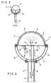
- FIGS. 2 and 3 correspond to a more particular application, in which the solar collector also constitutes a candelabrum.
- the senor seen externally comprises a vertical support leg 6, at the top of which is mounted a globe, the visible part of which is the outer sphere 1, formed by the assembly, along a plane of horizontal joint, of two hemispheres 3 and 4 in translucent material, such as metacrylate.
- the globe formed by these two half-spheres is supported by arches 15 available from the outside.
- the wall 16 and the interior hemisphere 2 delimit an internal hemispherical chamber 8, in which the fluid to be heated is sprayed.
- This fluid is supplied by a conduit 7 which passes through the support leg 6, also passes vertically through the lower half of the sphere, as well as the wall 16, and extends vertically upwards inside the chamber 8, to end with a spray head 10.
- the electrical supply to the ampule 18 is carried out by wires not indicated in the drawing but which obviously cross the support foot 6.
- the material of the hemisphere 4, under which is housed the bulb 18, is chosen with a color and other qualities that make it a good light diffuser.
- the wall 16, located above the bulb 18, is made reflective, which makes it possible to return towards the ground the light energy that the bulb emits upwards.
- an additional differential thermostat is provided, to control the circulation pump for the heat-transfer fluid, not shown, from a temperature probe 20 placed under the wall 16 which surmounts the bulb 18, the installation always comprising, in the usual way, a main differential thermostat which controls the supply of solar hot water into the stock to be heated, during the day, from a probe measuring the temperature of the stock.
- the switching to the "night” thermostat and the "day” thermostat is done automatically, by means of an electric timer.
- the solar collector combined with a candelabra which has just been described with reference to FIGS. 2 and 3, is applicable to the lighting of traffic lanes, squares, tenants adjoining buildings or industrial premises, parks , swimming pools (for which it also provides hot water), etc.
- the thermostats mentioned above may be common to the whole installation.
Abstract
Ce capteur solaire comprend deux sphères concentriques, la sphère extérieure 1 étant translucide et la sphère intérieure 2 étant absorbante vis-à-vis du rayonnement solaire. Le fluide à chauffer est amené par un conduit d'entrée 7, sur lequel est intercalée une pompe 9, et pulvérisé par une tête 10 dans la chambre sphérique interne 8. Il s'écoule le long de la paroi interne de la sphère intérieure 2, en se réchauffant, et est recueilli à la base de cette sphère intérieure, par un conduit de sortie 11. Ce capteur s'applique notamment à la production d'eau chaude, par exemple pour le chauffage des piscines; placé au sommet d'un pied-support 6, il peut constituer en outre un candélabre.This solar collector comprises two concentric spheres, the outer sphere 1 being translucent and the inner sphere 2 being absorbent against solar radiation. The fluid to be heated is brought through an inlet conduit 7, on which is interposed a pump 9, and sprayed by a head 10 into the internal spherical chamber 8. It flows along the internal wall of the internal sphere 2 , by heating up, and is collected at the base of this interior sphere, by an outlet duct 11. This sensor applies in particular to the production of hot water, for example for heating swimming pools; placed at the top of a support leg 6, it can also constitute a candelabrum.
Description
La présente invention se rapporte à un capteur solaire du type sphérique, présentant une structure relativement simplifiée.The present invention relates to a spherical type solar collector, having a relatively simplified structure.
Ce capteur solaire appartient au genre de ceux comprenant deux sphères concentriques, la sphère extérieure étant translucide et la sphère intérieure étant absorbante vis-à-vis du rayonnement solaire, ainsi que des conduits d'entrée et de sortie pour le fluide à chauffer.This solar collector belongs to the kind of those comprising two concentric spheres, the outer sphere being translucent and the inner sphere being absorbent with respect to solar radiation, as well as inlet and outlet conduits for the fluid to be heated.
On a déjà envisagé l'utilisation de tels capteurs pour la production d'eau chaude par "effet de serre", la forme sphérique permettant de produire de l'eau chaude avec un rendement qui n'est pas sensiblement modifié par la direction et l'angle d'incidence des rayons solaires. Dans ces capteurs, il convient de prévoir une circulation du fluide à chauffer, telle que le fluide se réchauffe au contact de la paroi de la sphère intérieure absorbante. Les projets actuellement connus prévoient, à cet effet, de faire passer le fluide à chauffer à travers un certain nombre de conduits et dans des chambres internes au capteur, notamment des chambres délimitées par deux parois sphériques ou hémisphériques concentriques. Il en résulte que la fabrication de tels capteurs solaires sphériques, reste, à l'heure actuelle, relativement complexe et coûteuse.We have already considered the use of such sensors for the production of hot water by "greenhouse effect", the spherical shape making it possible to produce hot water with a yield which is not appreciably modified by the direction and the angle of incidence of the sun's rays. In these sensors, a circulation of the fluid to be heated should be provided, such that the fluid heats up in contact with the wall of the absorbent interior sphere. Currently known projects provide for this purpose, to pass the fluid to be heated through a number of conduits and into chambers internal to the sensor, in particular chambers delimited by two concentric spherical or hemispherical walls. The result that the manufacture of such spherical solar collectors, remains, at present, relatively complex and expensive.
Pour éviter cet inconvénient, la présente invention fournit un capteur à structure simplifiée, donc économique, capable de produire de l'eau chaude avec un débit et une température suffisantes pour certaines applications, tel que, par exemple, le chauffage d'eau pour les piscines.To avoid this drawback, the present invention provides a sensor with a simplified, therefore economical structure, capable of producing hot water with a flow rate and a temperature sufficient for certain applications, such as, for example, heating water for swimming pools.
A cet effet, dans le capteur selon l'invention, le conduit d'entrée se prolonge vers le haut, à l'intérieur de la chamtte sphérique interne du capteur, l'extrémité interne dudit conduit portant une tête de pulvérisation, apte à projeter le fluide sur la paroi interne de la sphère intérieure absorbante, de telle sorte que le fluide s'écoule en se réchauffant le long de cette paroi interne, avant d'être recueilli à la base de la sphère intérieure absorbante.To this end, in the sensor according to the invention, the inlet duct extends upwards, inside the internal spherical chamber of the sensor, the inner end of said duct carrying a spray head, suitable for projecting the fluid on the inner wall of the absorbent inner sphere, so that the fluid flows by heating along this inner wall, before being collected at the base of the absorbent inner sphere.
Le fluide, projeté par une sorte de gicleur sur la paroi interne de la sphère intérieure, récupère les calories solaires accumulées dans l'espace délimité par les deux sphères concentriques, en s'écoulant le long de cette paroi. Du fluide réchauffé est ainsi recueilli, par l'effet de la seule gravité, à la base de la sphère intérieure, et évacué par le conduit de sortie qui le dirige vers un lieu d'utilisation et/ou de stockage.The fluid, projected by a kind of nozzle on the internal wall of the interior sphere, collects the solar calories accumulated in the space delimited by the two concentric spheres, by flowing along this wall. Heated fluid is thus collected, by the effect of gravity alone, at the base of the interior sphere, and evacuated by the outlet conduit which directs it to a place of use and / or storage.
Avantageusement, le capteur objet de l'invention comprend un pied-support vertical traversé par le conduit d'entrée précité, dont l'extrémité interne porte la tête de pulvérisation, ainsi que par le conduit de sortie qui recueille le fluide chauffé à la base de la sphère intérieure absorbante.Advantageously, the sensor object of the invention comprises a vertical support foot through which the aforementioned inlet duct, the internal end of which carries the spray head, as well as by the outlet duct which collects the heated fluid at the base of the absorbent inner sphere.
Un tel capteur solaire sphérique, avec pied-support, peut donner lieu à une version perfectionnée, constituant aussi un candélabre et trouvant ainsi une utilité à la fois durant le jour et pendant les heures d'obscurité.Such a spherical solar collector, with a support leg, can give rise to an improved version, also constituting a candelabra and thus finding utility both during the day and during the hours of darkness.
A cet effet, le volume délimité par la sphère extérieure translucide du capteur est divisé, par une paroi plane sensiblement horizontale, en deux moitiés dont celle supérieure comprend une demi-sphère intérieure absorbante qui, avec la paroi plane précitée, définit une chambre interne hémisphérique, dans laquelle est pulvérisé le fluide à chauffer, tandis que la moitié inférieure forme une autre chambre hémisphérique à l'intérieur de laquelle est disposée au moins une ampoule électrique, l'ensemble étant monté, à une certaine hauteur au-dessus du sol, au sommet du pied-support traversé par les conduits d'amenée et de retour du fluide à chauffer, ainsi que par les fils d'alimentation de l'ampoule, de manière à constituer un capteur solaire combiné à un candélabre.To this end, the volume delimited by the translucent outer sphere of the sensor is divided, by a substantially horizontal plane wall, into two halves, including that upper comprises an absorbent interior half-sphere which, with the aforementioned flat wall, defines an internal hemispherical chamber, in which the fluid to be heated is sprayed, while the lower half forms another hemispherical chamber inside which is disposed at the minus an electric bulb, the assembly being mounted, at a certain height above the ground, at the top of the support leg through which the supply and return conduits of the fluid to be heated, as well as by the supply wires of the bulb, so as to constitute a solar collector combined with a candelabra.
La partie supérieure de cet appareil forme le capteur solaire proprement dit, en forme de demi-sphère,mais reprenant intégralement le principe de pulvérisation exposé précédemment. La partie inférieure constitue un moyen d'éclairage, la sphère extérieure translucide remplissant, au niveau de cette partie, le rôle d'un diffuseur de lumière. L'ensemble possède une forme de globe, permettant une bonne intégration notamment dans un environnement urbain. Le fait que seule la moitié inférieure de ce globe soit utilisée pour l'éclairage ne constitue en aucun cas une insuffisance, car la partie supérieure du diffuseur d'un candélabre émet habituellement, vers le ciel, une énergie lumineuse qui est gaspillée. Bien au contraire, la paroi plane séparatrice, située au-dessus de l'ampoule, peut être prévue réfléchissante, ce qui permet, dans le cas de la présente invention, de renvoyer vers le sol l'énergie lumineuse de l'ampoule qui, habituellement, est perdue dans l'atmosphère. Il devient donc possible de réduire la puissance de l'ampoule, d'où une économie d'énergie pour l'éclairage.The upper part of this device forms the actual solar collector, in the form of a hemisphere, but fully incorporating the principle of spraying described above. The lower part constitutes a means of lighting, the translucent external sphere fulfilling, at this part, the role of a light diffuser. The whole has the shape of a globe, allowing a good integration in particular in an urban environment. The fact that only the lower half of this globe is used for lighting does not in any way constitute an insufficiency, since the upper part of the diffuser of a candelabra usually emits, towards the sky, light energy which is wasted. On the contrary, the planar separating wall, located above the bulb, can be provided reflecting, which allows, in the case of the present invention, to return to the ground the light energy of the bulb which, usually is lost to the atmosphere. It therefore becomes possible to reduce the power of the bulb, thereby saving energy for lighting.
Un autre résultat remarquable procure par cette forme de réalisation constituant aussi un candélabre, et apportant une économie d'énergie supplémentaire, consiste en la possibilité de récupérer la chaleur résiduelle de l'ampoule, pour chauffer le fluide durant la nuit. Pour récupérer cette énergie, il convient bien entendu de compléter les moyens de commande de l'installation, de manière à faire circuler aussi le fluide caloporteur durant les heures de nuit, lorsque l'ampoule fournit une chaleur utilisable. A cet effet, il est prévu par exemple un thermostat différentiel supplémentaire avec une sonde de température placée sous la paroi séparatrice qui surmonte l'ampoule, pour commander la pompe de circulation du fluide et chauffer ce dernier par récupération de la chaleur résiduelle de l'ampoule.Another remarkable result obtained by this embodiment also constituting a candelabra, and bringing an additional energy saving, consists in the possibility of recovering the residual heat of the bulb, to heat the fluid overnight. To recover this energy, it is of course necessary to com add to the control means of the installation, so as to also circulate the heat transfer fluid during the night hours, when the bulb provides usable heat. For this purpose, there is provided for example an additional differential thermostat with a temperature probe placed under the separating wall which surmounts the bulb, to control the fluid circulation pump and heat the latter by recovering the residual heat from the bulb.
De toute façon l'invention sera mieux comprise à l'aide de la description qui suit, en référence aux dessins schématiques annexés représentant, à titre d'exemples non limitatifs, deux formes de réalisation de ce capteur solaire sphérique :
- Figure 1 est une vue en coupe verticale d'un premier capteur solaire conforme à l'invention ;
- Figure 2 est une vue générale, en perspective, d'un autre capteur solaire conforme à la présente invention, constituant aussi un candélabre;
- Figure 3 est une vue en coupe verticale, à plus grande échelle, du capteur selon la figure 2.
- Figure 1 is a vertical sectional view of a first solar collector according to the invention;
- Figure 2 is a general perspective view of another solar collector according to the present invention, also constituting a candelabrum;
- Figure 3 is a vertical sectional view, on a larger scale, of the sensor according to Figure 2.
Le capteur solaire représenté à la figure 1 comprend deux sphères concentriques 1 et 2. La sphère extérieure 1 est formée par l'assemblage, suivant un plan de joint horizontal, de deux demi-sphères 3 et 4 en matériau translucide, par exemple en matériau synthétique transparent tel que polymétacrylate (connu sous la dénomination commerciale de PLEXIGLAS). La sphère intérieure 2, séparée de la sphère extérieure 1 par un espace 5 rempli d'air, peut être elle aussi formée par l'assemblage de deux demi-sphères ; cette seconde sphère 2, devant absorber le rayonnement solaire, est réalisée par exemple en métal peint d'une couleur noir mat.The solar collector shown in FIG. 1 comprises two
La sphère intérieure 2 est maintenue à l'intérieur de la sphère extérieure 1 au moyen d'un pied-support vertical 6, qui traverse la demi-sphère extérieure inférieure 4.The
Un conduit d'entrée 7, amenant vers le capteur le fluide à chauffer, pénètre par le bas dans la chambre sphérique interne 8 du capteur, en passant à travers le pied-support 6. Sur le conduit 7 est intercalée une pompe 9, située à l'extérieur du capteur ; ce conduit 7 se prolonge verticalement, vers le haut, à l'intérieur de la chambre 8, et l'extrémité interne de ce conduit 7, située dans la région supérieure de la chambre 8, porte une tête de pulvérisation 10.An
Un conduit de sortie 11, partant du point le plus bas de la chambre interne 8, sort enfin du capteur en traversant le pied-support 6.An
Le fluide à chauffer, par exemple de l'eau, est pulvérisé dans la chambre interne 8. Il vient ainsi frapper la paroi interne de la sphère intérieure 2, et s'écoule le long de cette paroi ; ce faisant, le fluide récupère les calories emmagasinées dans l'espace 5 et par la sphère 2. Le fluide chauffé est recuilli, à la base de la sphère intérieure 2, par le conduit de sortie 11, qui le dirige vers un lieu d'utilisation ou de stockage.The fluid to be heated, for example water, is sprayed into the
A ce capteur est associé un réflecteur 12, constitué par deux surfaces planes réfléchissantes 13 et 14 qui forment un certain angle obtus l'une par rapport à l'autre. La surface réfléchissante 13 est disposée horizontalement, sur le sol, au-dessous du capteur. L'autre surface réfléchissante 14 est inclinée et tournée vers le Sud.With this sensor is associated a
Le capteur solaire sphérique,à structure simplifiée, qui vient d'être décrit, est applicable à la production économique d'eau chaude, notamment pour le chauffage des piscines, et de façon générale à toutes les conversions thermo-solaires à basse température.The spherical solar collector, with a simplified structure, which has just been described, is applicable to the economical production of hot water, in particular for heating swimming pools, and in general to all thermo-solar conversions at low temperature.
Les figures 2 et 3 correspondent à une application plus particulière, dans laquelle le capteur solaire constitue aussi un candélabre.Figures 2 and 3 correspond to a more particular application, in which the solar collector also constitutes a candelabrum.
Comme le montre la figure 2, le capteur vu extérieurement comprend dans ce cas un pied-support vertical 6, au sommet duquel est monté un globe, dont la partie visible est la sphère extérieure 1, formée par l'assemblage, suivant un plan de joint horizontal, de deux demi-sphères 3 et 4 en matériau translucide, tel que métacrylate. Le globe formé de ces deux demi-sphères est supporté par des arceaux 15 à disposition extérieure.As shown in Figure 2, the sensor seen externally in this case comprises a
La figure 3 montre la structure interne de ce capteur solaire combiné à un candélabre :
- La moitié supérieure, séparée de la moitié inférieure par une paroi plane circulaire 16, constitue le capteur solaire proprement dit, et est réalisée selon la même conception que le capteur sphérique décrit en référence à la figure 1. Sous la demi-sphère extérieure 3 supérieure en matériau translucide, est prévue une demi-sphère intérieure 2, concentrique à la demi-sphère extérieure 3 et séparée de celle-ci par un
espace 5 rempli d'air ; la demi-sphère intérieure 2, devant absorber le rayonnement solaire, est réalisée par exemple en métal peint d'une couleur noir mat.
- The upper half, separated from the lower half by a circular
flat wall 16, constitutes the solar collector proper, and is produced according to the same design as the spherical collector described with reference to FIG. 1. Under the upperexternal hemisphere 3 made of translucent material, aninterior hemisphere 2 is provided, concentric with theexterior hemisphere 3 and separated from the latter by aspace 5 filled with air; theinterior hemisphere 2, which has to absorb solar radiation, is made for example from painted metal with a matt black color.
La paroi 16 et la demi-sphère intérieure 2 délimitent une chambre interne hémisphérique 8, dans laquelle est pulvérisé le fluide à chauffer. Ce fluide est amené par un conduit 7 qui passe à travers le pied-support 6, traverse aussi verticalement la moitié inférieure de la sphère, ainsi que la paroi 16, et se prolonge verticalement vers le haut à l'intérieur de la chambre 8, pour se terminer par une tête de pulvérisation 10. Un conduit de sortie 11, partant du point le plus bas de la chambre 8, donc partant au nDeau de la paroi 16, traverse lui-aussi, verticalement, la moitié inférieure de la sphère et le pied-support 6, pour recueillir le fluide chauffé et le diriger vers un lieu d'utilisation et/ou de stockage.The
La demi-sphère extérieure 4 inférieure, en matériau translucide légèrement teinté en blanc, délimite, avec la paroi horizontale 16, une autre chambre hémisphérique 17, à l'intérieur de laquelle est disposée une ampoule électrique 18, tenue par exemple au moyen d'un support 19 fixé sous la paroi 16. L'alimentation électrique de l'ampuule 18 est réalisée par des fils non indiqués sur le dessin mais qui traversent, évidemment, le pied-support 6. Le matériau de la demi-sphère 4, sous laquelle est logée l'ampoule 18, est choisi avec une couleur et d'autres qualités qui en font un bon diffuseur de la lumière. De plus, la paroi 16, située au-dessus de l'ampoule 18, est rendue réfléchissante, ce qui permet de renvoyer vers le sol l'énergie lumineuse que l'ampoule émet vers le haut.The lower external hemisphere 4, of translucent material slightly tinted in white, delimits, with the
Il est possible également de récupérer la chaleur résiduelle de l'ampoule 18, pendant la nuit, pour chauffer le fluide caloporteur. A cet effet, un thermostat différentiel supplémentaire est prévu, pour commander la pompe de circulation du fluide caloporteur, non représentée, à partir d'une sonde de température 20 placée sous la paroi 16 qui surmonte l'ampoule 18 l'installation comprenant toujours, de manière habituelle, un thermostat différentiel principal qui commande l'apport d'eau chaude solaire dans le stock à chauffer, pendant le jour, à partir d'une sonde mesurant la température du stock. La commutation sur le thermostat "nuit" et le thermostat "jour" est faite automatiquement, au moyen d'une minuterie électrique. Si l'on considère, dans la quantité d'énergie totale dissipée par une ampoule électrique, la part de l'énergie diffusée sous forme lumineuse, en la comparant à la quantité d'énergie absorbée, on s'aperçoit de l'intérêt réel qu'il y aurait à récupérer, comme on vient de le décrire, la quantité d'énergie perdue sous forme de chaleur résiduelle par l'ampoule 18.It is also possible to recover the residual heat from the
Le capteur solaire combiné à un candélabre, qui vient d'être décrit en référence aux figures 2 et 3, est applicable à l'éclairage de voies de circulation, de places, de tenains attenant à des immeubles ou à des locaux industriels, de parcs, de piscines (pour lesquelles il fournit aussi l'eau chaude), etc... Dans le cas d'une installation comprenant plusieurs capteurs similaires qui fonctionnent dans des conditions comparables, il est évident que les thermostats mentionnés plus haut peuvent être communs à toute l'installation.The solar collector combined with a candelabra, which has just been described with reference to FIGS. 2 and 3, is applicable to the lighting of traffic lanes, squares, tenants adjoining buildings or industrial premises, parks , swimming pools (for which it also provides hot water), etc. In the case of an installation comprising several similar sensors which operate under comparable conditions, it is obvious that the thermostats mentioned above may be common to the whole installation.
Comme il va de soi, l'invention ne se limite pas aux seules formes de réalisation de ce capteur solaire sphérique qui ont été décrites ci-dessus, à titre d'exemples ; elle en embrasse au contraire, toutes les variantes relevant du même principe.It goes without saying that the invention is not limited only embodiments of this spherical solar collector which have been described above, by way of examples; on the contrary, it embraces all variants relating to the same principle.
Claims (5)
Applications Claiming Priority (4)
| Application Number | Priority Date | Filing Date | Title |
|---|---|---|---|
| FR7918336 | 1979-07-16 | ||
| FR7918336A FR2461896A1 (en) | 1979-07-16 | 1979-07-16 | Solar energy collector - has vertical pipe and pump for spraying water over inner surface of inner one of two concentric spheres |
| FR8007224 | 1980-03-31 | ||
| FR808007224A FR2479433B2 (en) | 1980-03-31 | 1980-03-31 | SPHERICAL SOLAR COLLECTOR, WITH SIMPLIFIED STRUCTURE |
Publications (1)
| Publication Number | Publication Date |
|---|---|
| EP0022686A1 true EP0022686A1 (en) | 1981-01-21 |
Family
ID=26221268
Family Applications (1)
| Application Number | Title | Priority Date | Filing Date |
|---|---|---|---|
| EP80400833A Withdrawn EP0022686A1 (en) | 1979-07-16 | 1980-06-10 | Spherical solar collector with simplified structure |
Country Status (5)
| Country | Link |
|---|---|
| US (1) | US4344418A (en) |
| EP (1) | EP0022686A1 (en) |
| ES (1) | ES8104869A1 (en) |
| IL (1) | IL60374A0 (en) |
| OA (1) | OA06580A (en) |
Cited By (7)
| Publication number | Priority date | Publication date | Assignee | Title |
|---|---|---|---|---|
| EP0069103A1 (en) * | 1981-06-18 | 1983-01-05 | PATENTS AND RESEARCHES ESTABLISHMENT Société de droit du Liechtenstein dite: | Thermal solar collector with a film of flowing fluid |
| FR2512528A1 (en) * | 1981-09-10 | 1983-03-11 | Sanahuja Joseph | Solar energy collecting sphere - has photocells providing current and water container providing supply of heated water, and entire structure supported on central axis |
| US4404961A (en) * | 1980-11-17 | 1983-09-20 | Stuhlman Frank A | Apparatus for collecting solar energy |
| FR2556825A1 (en) * | 1983-12-16 | 1985-06-21 | Leroy Claude | MONOBLOC SOLAR WATER HEATER DEVICE AND SPHERICAL SHAPE |
| GB2211286A (en) * | 1987-10-05 | 1989-06-28 | John Delacretaz | Solar energy collector |
| DE19502070A1 (en) * | 1994-10-04 | 1996-04-11 | Stefan Reschberger | Solar thermal plant for generating electrical power and heat in adverse northern regions e.g. central and northern Europe, |
| US5620660A (en) * | 1993-12-03 | 1997-04-15 | Eppendorf-Netheler-Hinz Gmbh | Pipette system |
Families Citing this family (11)
| Publication number | Priority date | Publication date | Assignee | Title |
|---|---|---|---|---|
| US4537180A (en) * | 1981-10-21 | 1985-08-27 | Minor John W | Solar heating and storage unit |
| US4757803A (en) * | 1987-06-29 | 1988-07-19 | Dixon Larry J | Solar heater for mounting on a boat |
| US5676128A (en) * | 1995-07-10 | 1997-10-14 | Sun It Enterprises | Solar device for cooking or sterilizing and method or use thereof |
| US5915376A (en) * | 1996-02-20 | 1999-06-29 | Mclean; Vincent C. | Evacuated solar collector |
| US7669592B2 (en) * | 2006-03-20 | 2010-03-02 | Steven Polk | Solar power plant |
| US8165435B2 (en) * | 2009-03-16 | 2012-04-24 | Fernando Ramon Martin-Lopez | Solar energy collector |
| US20110088685A1 (en) * | 2009-10-16 | 2011-04-21 | Polk Sr Dale E | Solar dish collector system and associated methods |
| MX2011002035A (en) * | 2011-02-11 | 2012-08-30 | Fricaeco America S A De C V | Solar liquid heater. |
| JP2012202556A (en) * | 2011-03-23 | 2012-10-22 | Toshiba Corp | Solar heat collecting apparatus and solar power generating system |
| US9534811B2 (en) * | 2014-12-31 | 2017-01-03 | Fricaeco America, SAPI de C.V. | Solar fluid preheating system having a thermosiphonic aperture and concentrating and accelerating convective nanolenses |
| CN107469512B (en) * | 2017-07-03 | 2020-01-14 | 西安理工大学 | Haze system is subtracted in cooling that can remote control on being applied to street lamp |
Citations (5)
| Publication number | Priority date | Publication date | Assignee | Title |
|---|---|---|---|---|
| FR2178311A5 (en) * | 1972-03-27 | 1973-11-09 | Salmand Bernard | |
| FR2280857A1 (en) * | 1975-12-22 | 1976-02-27 | Claude Publicite Fr | Light unit with diffusing sphere - and screw mechanism in tubular mast to raise top hemisphere |
| US4056093A (en) * | 1975-12-05 | 1977-11-01 | Barger Harold E | Solar heater |
| US4136670A (en) * | 1977-06-13 | 1979-01-30 | Davis Theodore L | Solar heating collector apparatus |
| US4137903A (en) * | 1977-08-19 | 1979-02-06 | Annett Ii Charles E | Solar heat absorber |
Family Cites Families (2)
| Publication number | Priority date | Publication date | Assignee | Title |
|---|---|---|---|---|
| US3934573A (en) * | 1975-02-28 | 1976-01-27 | Dandini Alessandro O | Spherical system for the concentration and extraction of solar energy |
| US4237868A (en) * | 1978-09-14 | 1980-12-09 | Overton Charlie N | Solar heating balloon |
-
1980
- 1980-06-10 EP EP80400833A patent/EP0022686A1/en not_active Withdrawn
- 1980-06-23 IL IL60374A patent/IL60374A0/en unknown
- 1980-07-07 ES ES493168A patent/ES8104869A1/en not_active Expired
- 1980-07-09 US US06/167,013 patent/US4344418A/en not_active Expired - Lifetime
- 1980-07-12 OA OA57164A patent/OA06580A/en unknown
Patent Citations (5)
| Publication number | Priority date | Publication date | Assignee | Title |
|---|---|---|---|---|
| FR2178311A5 (en) * | 1972-03-27 | 1973-11-09 | Salmand Bernard | |
| US4056093A (en) * | 1975-12-05 | 1977-11-01 | Barger Harold E | Solar heater |
| FR2280857A1 (en) * | 1975-12-22 | 1976-02-27 | Claude Publicite Fr | Light unit with diffusing sphere - and screw mechanism in tubular mast to raise top hemisphere |
| US4136670A (en) * | 1977-06-13 | 1979-01-30 | Davis Theodore L | Solar heating collector apparatus |
| US4137903A (en) * | 1977-08-19 | 1979-02-06 | Annett Ii Charles E | Solar heat absorber |
Cited By (10)
| Publication number | Priority date | Publication date | Assignee | Title |
|---|---|---|---|---|
| US4404961A (en) * | 1980-11-17 | 1983-09-20 | Stuhlman Frank A | Apparatus for collecting solar energy |
| EP0069103A1 (en) * | 1981-06-18 | 1983-01-05 | PATENTS AND RESEARCHES ESTABLISHMENT Société de droit du Liechtenstein dite: | Thermal solar collector with a film of flowing fluid |
| FR2512528A1 (en) * | 1981-09-10 | 1983-03-11 | Sanahuja Joseph | Solar energy collecting sphere - has photocells providing current and water container providing supply of heated water, and entire structure supported on central axis |
| FR2556825A1 (en) * | 1983-12-16 | 1985-06-21 | Leroy Claude | MONOBLOC SOLAR WATER HEATER DEVICE AND SPHERICAL SHAPE |
| EP0147345A2 (en) * | 1983-12-16 | 1985-07-03 | Claude Leroy | Solar water heater |
| EP0147345A3 (en) * | 1983-12-16 | 1985-12-18 | Claude Leroy | Spherical monoblock for a solar water heater |
| GB2211286A (en) * | 1987-10-05 | 1989-06-28 | John Delacretaz | Solar energy collector |
| GB2211286B (en) * | 1987-10-05 | 1991-07-17 | John Delacretaz | Solar collector |
| US5620660A (en) * | 1993-12-03 | 1997-04-15 | Eppendorf-Netheler-Hinz Gmbh | Pipette system |
| DE19502070A1 (en) * | 1994-10-04 | 1996-04-11 | Stefan Reschberger | Solar thermal plant for generating electrical power and heat in adverse northern regions e.g. central and northern Europe, |
Also Published As
| Publication number | Publication date |
|---|---|
| OA06580A (en) | 1981-07-31 |
| US4344418A (en) | 1982-08-17 |
| IL60374A0 (en) | 1980-09-16 |
| ES493168A0 (en) | 1981-04-01 |
| ES8104869A1 (en) | 1981-04-01 |
Similar Documents
| Publication | Publication Date | Title |
|---|---|---|
| EP0022686A1 (en) | Spherical solar collector with simplified structure | |
| US4222372A (en) | Solar collector assembly | |
| US20110232631A1 (en) | Mosaic solar collector | |
| CH641269A5 (en) | CONCENTRATION DEVICE FOR CAPTURING AND FOCUSING SOLAR ENERGY AND CONVERTER APPARATUS COMPRISING THIS DEVICE. | |
| CA2789190C (en) | Solar collector having fresnel mirrors | |
| US8794229B2 (en) | Solar concentrator | |
| FR2873191A1 (en) | Rigging non-tracting focusing vacuum piping solar water heater | |
| US20120037152A9 (en) | Solar half parabolic shell smelter with a heliostat on a turntable | |
| US8800549B2 (en) | Solar energy collecting assembly | |
| US20160315583A1 (en) | Solar water-collecting, air-conditioning, light-transmitting and power generating house | |
| FR2479433A2 (en) | Solar energy collector - has vertical pipe and pump for spraying water over inner surface of inner one of two concentric spheres | |
| FR2558245A1 (en) | Solar heating system | |
| RU2569423C1 (en) | Solar heater with protection against precipitation | |
| RU2225966C1 (en) | Solar unit with concentrator | |
| FR2509844A1 (en) | SOLAR PLANAR SENSOR WITH CONCENTRATION AND GREENHOUSE EFFECT | |
| JPS5892753A (en) | Intensifying collector of solar heat | |
| FR2478279A1 (en) | Focussing mirror for solar radiation - has cylindrical-parabolic configuration with centre of gravity coinciding with focus for self-balancing | |
| FR2461210A1 (en) | Spherical type solar heat collector - has two separate water circuits in concentric spheres connected in series with one acting as pre-heat circuit | |
| CN210688777U (en) | Energy-concerving and environment-protective space can air heating system | |
| CN201954771U (en) | Solar energy device capable of heating inside and outside by spotlighting through strip convex lens | |
| FR2578963A1 (en) | Concentration and pointing system for a solar energy collector and accessories | |
| JPH08296905A (en) | Cone-shaped solar water-heater | |
| CN218544573U (en) | Can realize assembled yurt of heat supply leaded light | |
| FR2461896A1 (en) | Solar energy collector - has vertical pipe and pump for spraying water over inner surface of inner one of two concentric spheres | |
| CN107710421B (en) | The concentration photovoltaic system of floating |
Legal Events
| Date | Code | Title | Description |
|---|---|---|---|
| PUAI | Public reference made under article 153(3) epc to a published international application that has entered the european phase |
Free format text: ORIGINAL CODE: 0009012 |
|
| AK | Designated contracting states |
Designated state(s): AT BE CH DE GB IT LU NL SE |
|
| 17P | Request for examination filed |
Effective date: 19810124 |
|
| ITCL | It: translation for ep claims filed |
Representative=s name: JACOBACCI CASETTA & PERANI S.P.A. |
|
| TCAT | At: translation of patent claims filed | ||
| DET | De: translation of patent claims | ||
| STAA | Information on the status of an ep patent application or granted ep patent |
Free format text: STATUS: THE APPLICATION HAS BEEN WITHDRAWN |
|
| 18W | Application withdrawn |
Withdrawal date: 19820329 |
|
| RIN1 | Information on inventor provided before grant (corrected) |
Inventor name: LEROY, CLAUDE |