EP0022686A1 - Kugelförmiger Solarkollektor mit vereinfachter Struktur - Google Patents
Kugelförmiger Solarkollektor mit vereinfachter Struktur Download PDFInfo
- Publication number
- EP0022686A1 EP0022686A1 EP80400833A EP80400833A EP0022686A1 EP 0022686 A1 EP0022686 A1 EP 0022686A1 EP 80400833 A EP80400833 A EP 80400833A EP 80400833 A EP80400833 A EP 80400833A EP 0022686 A1 EP0022686 A1 EP 0022686A1
- Authority
- EP
- European Patent Office
- Prior art keywords
- sphere
- fluid
- solar collector
- internal
- bulb
- Prior art date
- Legal status (The legal status is an assumption and is not a legal conclusion. Google has not performed a legal analysis and makes no representation as to the accuracy of the status listed.)
- Withdrawn
Links
Images

Classifications
-
- F—MECHANICAL ENGINEERING; LIGHTING; HEATING; WEAPONS; BLASTING
- F24—HEATING; RANGES; VENTILATING
- F24S—SOLAR HEAT COLLECTORS; SOLAR HEAT SYSTEMS
- F24S23/00—Arrangements for concentrating solar-rays for solar heat collectors
- F24S23/70—Arrangements for concentrating solar-rays for solar heat collectors with reflectors
- F24S23/77—Arrangements for concentrating solar-rays for solar heat collectors with reflectors with flat reflective plates
-
- F—MECHANICAL ENGINEERING; LIGHTING; HEATING; WEAPONS; BLASTING
- F24—HEATING; RANGES; VENTILATING
- F24S—SOLAR HEAT COLLECTORS; SOLAR HEAT SYSTEMS
- F24S10/00—Solar heat collectors using working fluids
- F24S10/60—Solar heat collectors using working fluids the working fluids trickling freely over absorbing elements
-
- Y—GENERAL TAGGING OF NEW TECHNOLOGICAL DEVELOPMENTS; GENERAL TAGGING OF CROSS-SECTIONAL TECHNOLOGIES SPANNING OVER SEVERAL SECTIONS OF THE IPC; TECHNICAL SUBJECTS COVERED BY FORMER USPC CROSS-REFERENCE ART COLLECTIONS [XRACs] AND DIGESTS
- Y02—TECHNOLOGIES OR APPLICATIONS FOR MITIGATION OR ADAPTATION AGAINST CLIMATE CHANGE
- Y02B—CLIMATE CHANGE MITIGATION TECHNOLOGIES RELATED TO BUILDINGS, e.g. HOUSING, HOUSE APPLIANCES OR RELATED END-USER APPLICATIONS
- Y02B10/00—Integration of renewable energy sources in buildings
- Y02B10/20—Solar thermal
-
- Y—GENERAL TAGGING OF NEW TECHNOLOGICAL DEVELOPMENTS; GENERAL TAGGING OF CROSS-SECTIONAL TECHNOLOGIES SPANNING OVER SEVERAL SECTIONS OF THE IPC; TECHNICAL SUBJECTS COVERED BY FORMER USPC CROSS-REFERENCE ART COLLECTIONS [XRACs] AND DIGESTS
- Y02—TECHNOLOGIES OR APPLICATIONS FOR MITIGATION OR ADAPTATION AGAINST CLIMATE CHANGE
- Y02E—REDUCTION OF GREENHOUSE GAS [GHG] EMISSIONS, RELATED TO ENERGY GENERATION, TRANSMISSION OR DISTRIBUTION
- Y02E10/00—Energy generation through renewable energy sources
- Y02E10/40—Solar thermal energy, e.g. solar towers
- Y02E10/44—Heat exchange systems
Definitions
- the present invention relates to a spherical type solar collector, having a relatively simplified structure.
- This solar collector belongs to the kind of those comprising two concentric spheres, the outer sphere being translucent and the inner sphere being absorbent with respect to solar radiation, as well as inlet and outlet conduits for the fluid to be heated.
- the present invention provides a sensor with a simplified, therefore economical structure, capable of producing hot water with a flow rate and a temperature sufficient for certain applications, such as, for example, heating water for swimming pools.
- the inlet duct extends upwards, inside the internal spherical chamber of the sensor, the inner end of said duct carrying a spray head, suitable for projecting the fluid on the inner wall of the absorbent inner sphere, so that the fluid flows by heating along this inner wall, before being collected at the base of the absorbent inner sphere.
- the fluid projected by a kind of nozzle on the internal wall of the interior sphere, collects the solar calories accumulated in the space delimited by the two concentric spheres, by flowing along this wall. Heated fluid is thus collected, by the effect of gravity alone, at the base of the interior sphere, and evacuated by the outlet conduit which directs it to a place of use and / or storage.
- the sensor object of the invention comprises a vertical support foot through which the aforementioned inlet duct, the internal end of which carries the spray head, as well as by the outlet duct which collects the heated fluid at the base of the absorbent inner sphere.
- Such a spherical solar collector, with a support leg, can give rise to an improved version, also constituting a candelabra and thus finding utility both during the day and during the hours of darkness.
- the volume delimited by the translucent outer sphere of the sensor is divided, by a substantially horizontal plane wall, into two halves, including that upper comprises an absorbent interior half-sphere which, with the aforementioned flat wall, defines an internal hemispherical chamber, in which the fluid to be heated is sprayed, while the lower half forms another hemispherical chamber inside which is disposed at the minus an electric bulb, the assembly being mounted, at a certain height above the ground, at the top of the support leg through which the supply and return conduits of the fluid to be heated, as well as by the supply wires of the bulb, so as to constitute a solar collector combined with a candelabra.
- the upper part of this device forms the actual solar collector, in the form of a hemisphere, but fully incorporating the principle of spraying described above.
- the lower part constitutes a means of lighting, the translucent external sphere fulfilling, at this part, the role of a light diffuser.
- the whole has the shape of a globe, allowing a good integration in particular in an urban environment.
- the fact that only the lower half of this globe is used for lighting does not in any way constitute an insufficiency, since the upper part of the diffuser of a candelabra usually emits, towards the sky, light energy which is wasted.
- planar separating wall located above the bulb, can be provided reflecting, which allows, in the case of the present invention, to return to the ground the light energy of the bulb which, usually is lost to the atmosphere. It therefore becomes possible to reduce the power of the bulb, thereby saving energy for lighting.
- the solar collector shown in FIG. 1 comprises two concentric spheres 1 and 2.
- the outer sphere 1 is formed by the assembly, along a horizontal joint plane, of two hemispheres 3 and 4 made of translucent material, for example material transparent synthetic such as polymetacrylate (known under the trade name of PLEXIGLAS).
- the inner sphere 2, separated from the outer sphere 1 by a space 5 filled with air, can also be formed by the assembly of two half-spheres; this second sphere 2, having to absorb solar radiation, is made for example of metal painted in a matt black color.
- the inner sphere 2 is held inside the outer sphere 1 by means of a vertical support leg 6, which passes through the lower outer hemisphere 4.
- a pump 9 located outside the sensor; this conduit 7 extends vertically, upwards, inside the chamber 8, and the internal end of this conduit 7, located in the upper region of the chamber 8, carries a spray head 10.
- the fluid to be heated for example water
- the fluid to be heated is sprayed into the internal chamber 8. It thus strikes the internal wall of the internal sphere 2, and flows along this wall; in doing so, the fluid recovers the calories stored in space 5 and by the sphere 2.
- the heated fluid is collected, at the base of the interior sphere 2, by the outlet duct 11, which directs it to a place of use or storage.
- a reflector 12 constituted by two reflecting flat surfaces 13 and 14 which form a certain obtuse angle with respect to each other.
- the reflecting surface 13 is arranged horizontally, on the ground, below the sensor.
- the other reflecting surface 14 is inclined and facing south.
- the spherical solar collector with a simplified structure, which has just been described, is applicable to the economical production of hot water, in particular for heating swimming pools, and in general to all thermo-solar conversions at low temperature.
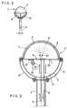
- FIGS. 2 and 3 correspond to a more particular application, in which the solar collector also constitutes a candelabrum.
- the senor seen externally comprises a vertical support leg 6, at the top of which is mounted a globe, the visible part of which is the outer sphere 1, formed by the assembly, along a plane of horizontal joint, of two hemispheres 3 and 4 in translucent material, such as metacrylate.
- the globe formed by these two half-spheres is supported by arches 15 available from the outside.
- the wall 16 and the interior hemisphere 2 delimit an internal hemispherical chamber 8, in which the fluid to be heated is sprayed.
- This fluid is supplied by a conduit 7 which passes through the support leg 6, also passes vertically through the lower half of the sphere, as well as the wall 16, and extends vertically upwards inside the chamber 8, to end with a spray head 10.
- the electrical supply to the ampule 18 is carried out by wires not indicated in the drawing but which obviously cross the support foot 6.
- the material of the hemisphere 4, under which is housed the bulb 18, is chosen with a color and other qualities that make it a good light diffuser.
- the wall 16, located above the bulb 18, is made reflective, which makes it possible to return towards the ground the light energy that the bulb emits upwards.
- an additional differential thermostat is provided, to control the circulation pump for the heat-transfer fluid, not shown, from a temperature probe 20 placed under the wall 16 which surmounts the bulb 18, the installation always comprising, in the usual way, a main differential thermostat which controls the supply of solar hot water into the stock to be heated, during the day, from a probe measuring the temperature of the stock.
- the switching to the "night” thermostat and the "day” thermostat is done automatically, by means of an electric timer.
- the solar collector combined with a candelabra which has just been described with reference to FIGS. 2 and 3, is applicable to the lighting of traffic lanes, squares, tenants adjoining buildings or industrial premises, parks , swimming pools (for which it also provides hot water), etc.
- the thermostats mentioned above may be common to the whole installation.
Applications Claiming Priority (4)
| Application Number | Priority Date | Filing Date | Title |
|---|---|---|---|
| FR7918336 | 1979-07-16 | ||
| FR7918336A FR2461896A1 (fr) | 1979-07-16 | 1979-07-16 | Capteur solaire spherique, a structure simplifiee |
| FR8007224 | 1980-03-31 | ||
| FR808007224A FR2479433B2 (fr) | 1980-03-31 | 1980-03-31 | Capteur solaire spherique, a structure simplifiee |
Publications (1)
| Publication Number | Publication Date |
|---|---|
| EP0022686A1 true EP0022686A1 (de) | 1981-01-21 |
Family
ID=26221268
Family Applications (1)
| Application Number | Title | Priority Date | Filing Date |
|---|---|---|---|
| EP80400833A Withdrawn EP0022686A1 (de) | 1979-07-16 | 1980-06-10 | Kugelförmiger Solarkollektor mit vereinfachter Struktur |
Country Status (5)
| Country | Link |
|---|---|
| US (1) | US4344418A (de) |
| EP (1) | EP0022686A1 (de) |
| ES (1) | ES8104869A1 (de) |
| IL (1) | IL60374A0 (de) |
| OA (1) | OA06580A (de) |
Cited By (7)
| Publication number | Priority date | Publication date | Assignee | Title |
|---|---|---|---|---|
| EP0069103A1 (de) * | 1981-06-18 | 1983-01-05 | PATENTS AND RESEARCHES ESTABLISHMENT Société de droit du Liechtenstein dite: | Thermischer Sonnenkollektor mit einem strömenden Flüssigkeitsfilm |
| FR2512528A1 (fr) * | 1981-09-10 | 1983-03-11 | Sanahuja Joseph | Capteur solaire produisant du courant electrique et de l'eau chaude |
| US4404961A (en) * | 1980-11-17 | 1983-09-20 | Stuhlman Frank A | Apparatus for collecting solar energy |
| FR2556825A1 (fr) * | 1983-12-16 | 1985-06-21 | Leroy Claude | Dispositif de chauffe-eau solaire monobloc et de forme spherique |
| GB2211286A (en) * | 1987-10-05 | 1989-06-28 | John Delacretaz | Solar energy collector |
| DE19502070A1 (de) * | 1994-10-04 | 1996-04-11 | Stefan Reschberger | Solarthermische Anlage zur Erzeugung elektrischer Energie und Wärme |
| US5620660A (en) * | 1993-12-03 | 1997-04-15 | Eppendorf-Netheler-Hinz Gmbh | Pipette system |
Families Citing this family (11)
| Publication number | Priority date | Publication date | Assignee | Title |
|---|---|---|---|---|
| US4537180A (en) * | 1981-10-21 | 1985-08-27 | Minor John W | Solar heating and storage unit |
| US4757803A (en) * | 1987-06-29 | 1988-07-19 | Dixon Larry J | Solar heater for mounting on a boat |
| US5676128A (en) * | 1995-07-10 | 1997-10-14 | Sun It Enterprises | Solar device for cooking or sterilizing and method or use thereof |
| US5915376A (en) * | 1996-02-20 | 1999-06-29 | Mclean; Vincent C. | Evacuated solar collector |
| US7669592B2 (en) * | 2006-03-20 | 2010-03-02 | Steven Polk | Solar power plant |
| US8165435B2 (en) * | 2009-03-16 | 2012-04-24 | Fernando Ramon Martin-Lopez | Solar energy collector |
| US20110088685A1 (en) * | 2009-10-16 | 2011-04-21 | Polk Sr Dale E | Solar dish collector system and associated methods |
| MX2011002035A (es) * | 2011-02-11 | 2012-08-30 | Fricaeco America S A De C V | Calentador solar de líquidos. |
| JP2012202556A (ja) * | 2011-03-23 | 2012-10-22 | Toshiba Corp | 太陽熱集熱装置及び太陽熱発電システム |
| US9534811B2 (en) * | 2014-12-31 | 2017-01-03 | Fricaeco America, SAPI de C.V. | Solar fluid preheating system having a thermosiphonic aperture and concentrating and accelerating convective nanolenses |
| CN107469512B (zh) * | 2017-07-03 | 2020-01-14 | 西安理工大学 | 应用于路灯上能远程控制的降温减霾系统 |
Citations (5)
| Publication number | Priority date | Publication date | Assignee | Title |
|---|---|---|---|---|
| FR2178311A5 (de) * | 1972-03-27 | 1973-11-09 | Salmand Bernard | |
| FR2280857A1 (fr) * | 1975-12-22 | 1976-02-27 | Claude Publicite Fr | Systeme lumineux a sphere diffusante |
| US4056093A (en) * | 1975-12-05 | 1977-11-01 | Barger Harold E | Solar heater |
| US4136670A (en) * | 1977-06-13 | 1979-01-30 | Davis Theodore L | Solar heating collector apparatus |
| US4137903A (en) * | 1977-08-19 | 1979-02-06 | Annett Ii Charles E | Solar heat absorber |
Family Cites Families (2)
| Publication number | Priority date | Publication date | Assignee | Title |
|---|---|---|---|---|
| US3934573A (en) * | 1975-02-28 | 1976-01-27 | Dandini Alessandro O | Spherical system for the concentration and extraction of solar energy |
| US4237868A (en) * | 1978-09-14 | 1980-12-09 | Overton Charlie N | Solar heating balloon |
-
1980
- 1980-06-10 EP EP80400833A patent/EP0022686A1/de not_active Withdrawn
- 1980-06-23 IL IL60374A patent/IL60374A0/xx unknown
- 1980-07-07 ES ES493168A patent/ES8104869A1/es not_active Expired
- 1980-07-09 US US06/167,013 patent/US4344418A/en not_active Expired - Lifetime
- 1980-07-12 OA OA57164A patent/OA06580A/xx unknown
Patent Citations (5)
| Publication number | Priority date | Publication date | Assignee | Title |
|---|---|---|---|---|
| FR2178311A5 (de) * | 1972-03-27 | 1973-11-09 | Salmand Bernard | |
| US4056093A (en) * | 1975-12-05 | 1977-11-01 | Barger Harold E | Solar heater |
| FR2280857A1 (fr) * | 1975-12-22 | 1976-02-27 | Claude Publicite Fr | Systeme lumineux a sphere diffusante |
| US4136670A (en) * | 1977-06-13 | 1979-01-30 | Davis Theodore L | Solar heating collector apparatus |
| US4137903A (en) * | 1977-08-19 | 1979-02-06 | Annett Ii Charles E | Solar heat absorber |
Cited By (10)
| Publication number | Priority date | Publication date | Assignee | Title |
|---|---|---|---|---|
| US4404961A (en) * | 1980-11-17 | 1983-09-20 | Stuhlman Frank A | Apparatus for collecting solar energy |
| EP0069103A1 (de) * | 1981-06-18 | 1983-01-05 | PATENTS AND RESEARCHES ESTABLISHMENT Société de droit du Liechtenstein dite: | Thermischer Sonnenkollektor mit einem strömenden Flüssigkeitsfilm |
| FR2512528A1 (fr) * | 1981-09-10 | 1983-03-11 | Sanahuja Joseph | Capteur solaire produisant du courant electrique et de l'eau chaude |
| FR2556825A1 (fr) * | 1983-12-16 | 1985-06-21 | Leroy Claude | Dispositif de chauffe-eau solaire monobloc et de forme spherique |
| EP0147345A2 (de) * | 1983-12-16 | 1985-07-03 | Claude Leroy | Solarwassererhitzer |
| EP0147345A3 (en) * | 1983-12-16 | 1985-12-18 | Claude Leroy | Spherical monoblock for a solar water heater |
| GB2211286A (en) * | 1987-10-05 | 1989-06-28 | John Delacretaz | Solar energy collector |
| GB2211286B (en) * | 1987-10-05 | 1991-07-17 | John Delacretaz | Solar collector |
| US5620660A (en) * | 1993-12-03 | 1997-04-15 | Eppendorf-Netheler-Hinz Gmbh | Pipette system |
| DE19502070A1 (de) * | 1994-10-04 | 1996-04-11 | Stefan Reschberger | Solarthermische Anlage zur Erzeugung elektrischer Energie und Wärme |
Also Published As
| Publication number | Publication date |
|---|---|
| ES493168A0 (es) | 1981-04-01 |
| OA06580A (fr) | 1981-07-31 |
| IL60374A0 (en) | 1980-09-16 |
| US4344418A (en) | 1982-08-17 |
| ES8104869A1 (es) | 1981-04-01 |
Similar Documents
| Publication | Publication Date | Title |
|---|---|---|
| EP0022686A1 (de) | Kugelförmiger Solarkollektor mit vereinfachter Struktur | |
| US4222372A (en) | Solar collector assembly | |
| US20110232631A1 (en) | Mosaic solar collector | |
| CH641269A5 (fr) | Dispositif de concentration destine a capter et a focaliser l'energie solaire et appareil convertisseur comprenant ce dispositif. | |
| CA2789190C (fr) | Capteur solaire a miroirs de fresnel | |
| US8794229B2 (en) | Solar concentrator | |
| FR2873191A1 (fr) | Chauffe-eau solaire a tube a vide ayant un foyer qui suit librement un profil a deux pentes | |
| US20120037152A9 (en) | Solar half parabolic shell smelter with a heliostat on a turntable | |
| US8800549B2 (en) | Solar energy collecting assembly | |
| US20160315583A1 (en) | Solar water-collecting, air-conditioning, light-transmitting and power generating house | |
| FR2479433A2 (fr) | Capteur solaire spherique, a structure simplifiee | |
| FR2558245A1 (fr) | Installation de chauffage solaire | |
| RU2569423C1 (ru) | Солнечный нагреватель с защитой от атмосферных осадков | |
| RU2225966C1 (ru) | Солнечный модуль с концентратором (варианты) | |
| FR2509844A1 (fr) | Capteur solaire plan a effet de concentration et de serre | |
| JPS5892753A (ja) | 太陽熱の高温化集熱器 | |
| FR2478279A1 (fr) | Concentrateur solaire cylindro-parabolique | |
| FR2461210A1 (fr) | Capteur solaire du type spherique | |
| CN210688777U (zh) | 一种节能环保的太空能空气加热系统 | |
| CN201954771U (zh) | 用条凸镜聚光内外加热太阳能装置 | |
| FR2578963A1 (fr) | Systeme de concentration et de pointage pour capteur d'energie solaire et accessoires | |
| JPH08296905A (ja) | 円錐型太陽熱温水器 | |
| CN218544573U (zh) | 可实现供热导光的装配式蒙古包 | |
| FR2461896A1 (fr) | Capteur solaire spherique, a structure simplifiee | |
| CN107710421B (zh) | 漂浮的集中光伏系统 |
Legal Events
| Date | Code | Title | Description |
|---|---|---|---|
| PUAI | Public reference made under article 153(3) epc to a published international application that has entered the european phase |
Free format text: ORIGINAL CODE: 0009012 |
|
| AK | Designated contracting states |
Designated state(s): AT BE CH DE GB IT LU NL SE |
|
| 17P | Request for examination filed |
Effective date: 19810124 |
|
| ITCL | It: translation for ep claims filed |
Representative=s name: JACOBACCI CASETTA & PERANI S.P.A. |
|
| TCAT | At: translation of patent claims filed | ||
| DET | De: translation of patent claims | ||
| STAA | Information on the status of an ep patent application or granted ep patent |
Free format text: STATUS: THE APPLICATION HAS BEEN WITHDRAWN |
|
| 18W | Application withdrawn |
Withdrawal date: 19820329 |
|
| RIN1 | Information on inventor provided before grant (corrected) |
Inventor name: LEROY, CLAUDE |