EP0022133B1 - Apparatus for coating articles with enamel slip - Google Patents
Apparatus for coating articles with enamel slip Download PDFInfo
- Publication number
- EP0022133B1 EP0022133B1 EP80890074A EP80890074A EP0022133B1 EP 0022133 B1 EP0022133 B1 EP 0022133B1 EP 80890074 A EP80890074 A EP 80890074A EP 80890074 A EP80890074 A EP 80890074A EP 0022133 B1 EP0022133 B1 EP 0022133B1
- Authority
- EP
- European Patent Office
- Prior art keywords
- parts
- shell
- container
- slip
- objects
- Prior art date
- Legal status (The legal status is an assumption and is not a legal conclusion. Google has not performed a legal analysis and makes no representation as to the accuracy of the status listed.)
- Expired
Links
- 210000003298 dental enamel Anatomy 0.000 title claims description 8
- 239000011248 coating agent Substances 0.000 title claims 2
- 238000000576 coating method Methods 0.000 title claims 2
- 241000272165 Charadriidae Species 0.000 claims description 5
- 239000007779 soft material Substances 0.000 claims description 3
- 238000007789 sealing Methods 0.000 claims description 2
- 239000011148 porous material Substances 0.000 description 4
- 238000001816 cooling Methods 0.000 description 2
- 238000001035 drying Methods 0.000 description 1
- 229920001821 foam rubber Polymers 0.000 description 1
- 239000002184 metal Substances 0.000 description 1
- 230000035515 penetration Effects 0.000 description 1
- 239000002002 slurry Substances 0.000 description 1
Images
Classifications
-
- C—CHEMISTRY; METALLURGY
- C23—COATING METALLIC MATERIAL; COATING MATERIAL WITH METALLIC MATERIAL; CHEMICAL SURFACE TREATMENT; DIFFUSION TREATMENT OF METALLIC MATERIAL; COATING BY VACUUM EVAPORATION, BY SPUTTERING, BY ION IMPLANTATION OR BY CHEMICAL VAPOUR DEPOSITION, IN GENERAL; INHIBITING CORROSION OF METALLIC MATERIAL OR INCRUSTATION IN GENERAL
- C23D—ENAMELLING OF, OR APPLYING A VITREOUS LAYER TO, METALS
- C23D11/00—Continuous processes; Apparatus therefor
-
- B—PERFORMING OPERATIONS; TRANSPORTING
- B01—PHYSICAL OR CHEMICAL PROCESSES OR APPARATUS IN GENERAL
- B01J—CHEMICAL OR PHYSICAL PROCESSES, e.g. CATALYSIS OR COLLOID CHEMISTRY; THEIR RELEVANT APPARATUS
- B01J3/00—Processes of utilising sub-atmospheric or super-atmospheric pressure to effect chemical or physical change of matter; Apparatus therefor
- B01J3/006—Processes utilising sub-atmospheric pressure; Apparatus therefor
-
- B—PERFORMING OPERATIONS; TRANSPORTING
- B05—SPRAYING OR ATOMISING IN GENERAL; APPLYING FLUENT MATERIALS TO SURFACES, IN GENERAL
- B05C—APPARATUS FOR APPLYING FLUENT MATERIALS TO SURFACES, IN GENERAL
- B05C3/00—Apparatus in which the work is brought into contact with a bulk quantity of liquid or other fluent material
- B05C3/02—Apparatus in which the work is brought into contact with a bulk quantity of liquid or other fluent material the work being immersed in the liquid or other fluent material
- B05C3/09—Apparatus in which the work is brought into contact with a bulk quantity of liquid or other fluent material the work being immersed in the liquid or other fluent material for treating separate articles
-
- C—CHEMISTRY; METALLURGY
- C23—COATING METALLIC MATERIAL; COATING MATERIAL WITH METALLIC MATERIAL; CHEMICAL SURFACE TREATMENT; DIFFUSION TREATMENT OF METALLIC MATERIAL; COATING BY VACUUM EVAPORATION, BY SPUTTERING, BY ION IMPLANTATION OR BY CHEMICAL VAPOUR DEPOSITION, IN GENERAL; INHIBITING CORROSION OF METALLIC MATERIAL OR INCRUSTATION IN GENERAL
- C23D—ENAMELLING OF, OR APPLYING A VITREOUS LAYER TO, METALS
- C23D5/00—Coating with enamels or vitreous layers
- C23D5/02—Coating with enamels or vitreous layers by wet methods
Definitions
- the invention relates to a device for covering objects, preferably mufflers or similar hollow bodies with enamel slip, with an evacuable container consisting of two, preferably pivotable, shell-like parts that can be moved and moved away from one another, for receiving the objects to be covered, at least one of which Parts can be connected to a vacuum source, devices for supplying and removing enamel slip being provided.
- DE-A 2 028 079 discloses a device for applying enamel slip from a storage container to objects to be enamelled in an order space, which is formed by a trough which is closed by a cover and which is connected to a suction or pressure line and dips into the slurry of the storage container via a suction pipe which can be closed by a valve, a support, for example a grate, being provided in the order space for receiving the object to be enamelled.
- the container receiving the objects to be treated consists of a trough and a lid, which form a horizontal division plane.
- AT-B 265 814 which comprises a vessel (bell or caisson) which is open at the bottom and which can be connected to a vacuum source.
- the objects to be coated are held above an enamel slip reservoir above the slip level, and the bell is lowered over the objects until their edge dips into the slip. The bell is then evacuated to vent fine cracks, pores and the like of the objects and to then suck the slip into the bell.
- the evacuable container is divided in the vertical plane and the edges of the shell-like parts are bordered with a seal made of soft material, in which the holders for the objects are sealed can impress.
- the division according to the application saves time-consuming steps, such as e.g. B. placing the enamelled goods on a grate or re-attaching and pivoting the lid back or back.
- the measure according to the invention offers the possibility that, after opening the container, the objects to be enamelled are suspended on a thin wire of an endlessly circulating conveyor system and moved into the treatment room, remain in the treatment room and can then also be moved out of it.
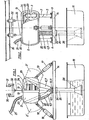
- the generally designated 1 container is divided according to a vertical plane and therefore consists of two shell-like parts 2 and 3. Each of these parts 2, 3 is rigidly attached to two stilts or supports 4, 5 or 6, 7 respectively. The stilts 4, 5; 6, 7 are mounted in joints 8, 9 and 10, 11 and can be pivoted about horizontal axes. Each of the parts 2, 3 carries on its edge a self-contained seal 12 or 13 made of very soft material, such as foam rubber with closed pores or the like.
- the joints 8 to 11 are mounted on a frame 14 which is held in a stationary manner above a slip storage container 15 in a manner not shown.
- Pneumatic working cylinders 16, 17 are also articulated on the frame 14, the piston rods 18 and 19 of which each engage one of the shell-like parts 2, 3.
- the shell-like part 2 is provided on its upper side with a valve 20, from which a hose 21 leading to a vacuum wave (not shown) extends.
- Another hose connector 22 is located on the underside of part 2; from this connector, a hose 23 leads to one attached to the frame 14 th connector 24.
- This connector 24 carries a pipe socket 25 with valve 26th
- two transport rails 30, 31 are provided above the container 1 for carriages 32 movable thereon in the manner of a monorail, orbit or the like.
- a support rod 34 is fastened to wires, thin rods or to sheet metal strips 33 which extend from the carriage 32, to which the objects 29 to be coated are fastened by means of wire pieces 35 or the like.
- the bead-like, very soft seals 12, 13 meet each other and also fit snugly and sealingly against the wires 33 or the like.
- the container is closed.
- the valve 26 is now closed and after opening the valve 20, the air contained in the container 1 is largely extracted via the hose 21.
- the valve 26 is opened.
- slip is sucked in through the hose 23 into the container until it is completely filled.
- the objects 29 are now completely immersed in slip, which, due to the previous suction of the air, can penetrate into all the gaps, pores, cracks and other free spaces in the objects 29.
- the valve 26 After a residence time given by experience, during which the valve 26 can be closed, the hose 21 is pressurized with the air pressure or with excess pressure, the valves 20 and 26 are opened. The slip in the container 2 is thereby very quickly pressed back into the storage container 15.
- the shell-like parts 2 and 3 are pivoted back into the positions 2 'and 3'; the container 1 is thereby opened.
- the objects 29, which are now evenly coated with slip, can be brought to further treatment stations (for example drying, cooling, burning, cooling, final assembly and so on) by means of the carriage 32.
- the invention is not restricted to the exemplary embodiment shown.
- a purely mechanical drive for moving the shell-like parts 2 and 3 can also be provided. It may also be advantageous not to fasten the two shell-like parts 2 and 3 to stilts (parts 4 to 7, as shown), but to guide them on slide rails or the like and thus to make them mutually parallel or separable .
Landscapes
- Chemical & Material Sciences (AREA)
- Organic Chemistry (AREA)
- Engineering & Computer Science (AREA)
- Materials Engineering (AREA)
- Mechanical Engineering (AREA)
- Metallurgy (AREA)
- Chemical Kinetics & Catalysis (AREA)
- Coating Apparatus (AREA)
- Application Of Or Painting With Fluid Materials (AREA)
Description
Die Erfindung betrifft eine Vorrichtung zum Überziehen von Gegenständen, vorzugsweise von Auspufftöpfen oder dergleichen Hohlkörpern mit Emailschlicker, mit einem evakuierbaren, aus zwei gegeneinander und voneinander weg bewegbaren, vorzugsweise schwenkbaren, schalenartigen Teilen bestehenden Behältern zur Aufnahme der zu überziehenden Gegenstände, von welchen zumindest einer der Teile mit einer Unterdruckquelle verbindbar ist, wobei Einrichtungen zur Zufuhr und zum Wegbringen von Emailschlicker vorgesehen sind.The invention relates to a device for covering objects, preferably mufflers or similar hollow bodies with enamel slip, with an evacuable container consisting of two, preferably pivotable, shell-like parts that can be moved and moved away from one another, for receiving the objects to be covered, at least one of which Parts can be connected to a vacuum source, devices for supplying and removing enamel slip being provided.
Durch die DE-A 2 028 079 ist eine Einrichtung zum Auftragen von Emailschlicker aus einem Vorratsbehälter auf zu emaillierende Gegenstände in einem Auftragsraum bekannt geworden, welcher von einer durch einen Deckel abgeschlossenen Wanne gebildet ist, welche an eine Saug- bzw. Druckleitung angeschlossen ist und über ein durch Ventil abschließbares Ansaugrohr in den Schlicker des Vorratsbehälters taucht, wobei im Auftragsraum eine Auflage, beispielsweise ein Rost zur Aufnahme des zu emaillierenden Gegenstandes vorgesehen ist. Bei dieser Einrichtung besteht der die zu behandelnden Gegenstände aufnehmende Behälter aus einer Wanne und einem Deckel, die eine horizontale Teilungsebene bilden.DE-A 2 028 079 discloses a device for applying enamel slip from a storage container to objects to be enamelled in an order space, which is formed by a trough which is closed by a cover and which is connected to a suction or pressure line and dips into the slurry of the storage container via a suction pipe which can be closed by a valve, a support, for example a grate, being provided in the order space for receiving the object to be enamelled. In this device, the container receiving the objects to be treated consists of a trough and a lid, which form a horizontal division plane.
Durch die AT-B 265 814 ist eine andere Vorrichtung dieser Art bekannt geworden, die ein nach unten offenes Gefäß (Glocke oder Caisson) umfaßt, welches mit einer Unterdruckquelle in Verbindung gebracht werden kann. Die zu überziehenden Gegenstände werden über einem Vorratsgefäß für Emailschlicker oberhalb des Schlickerspiegels gehalten, und die Glocke wird über die Gegenstände abgesenkt, bis ihr Rand in den Schlicker eintaucht. Die Glocke wird sodann evakuiert, um auch feine Spalten, Poren und dergleichen der Gegenstände zu entlüften und um danach den Schlicker in die Glocke einzusaugen.Another device of this type has become known from AT-B 265 814 which comprises a vessel (bell or caisson) which is open at the bottom and which can be connected to a vacuum source. The objects to be coated are held above an enamel slip reservoir above the slip level, and the bell is lowered over the objects until their edge dips into the slip. The bell is then evacuated to vent fine cracks, pores and the like of the objects and to then suck the slip into the bell.
Mit diesen Vorrichtungen kann wohl ein sehr gutes Eindringen des Emailschlickers in Poren, Schlitze und dergleichen kleine Hohlräume der Gegenstände erzielt werden ; nachteilig ist jedoch, daß die zu überziehenden, nur einzeln nach Verschwenken des Deckels bzw. Heben der Glocke in zeitraubender Arbeit auf die Halterung gebracht und nach dem Überziehen wieder weggenommen werden können. Des weiteren mußte die Glocke, um das Anbringen und Wegnehmen der Gegenstände zu erleichtern, sehr hoch angehoben werden ; andererseits mußt die Glocke aber auch weit abgesenkt werden, um auch nach dem Absinken des Schlickerspiegels infolge des Einsaugens des Schlickers in die Glocke die Abdichtung zwischen Glockenrand und Schlicker sicherzustellen. Alle diese Umstände machten ein schnelles Arbeiten und damit das rasche Überziehen vieler Gegenstände in kurzen Zeitabständen unmöglich.With these devices, a very good penetration of the enamel slip into pores, slits and the like, small cavities of the objects can be achieved; it is disadvantageous, however, that the covers which are to be pulled over can only be brought onto the holder in time-consuming work after pivoting the cover or lifting the bell and can be removed again after the pulling over. Furthermore, the bell had to be raised very high in order to make it easier to attach and remove the objects; on the other hand, the bell must also be lowered far enough to ensure the seal between the edge of the bell and the slip even after the slip level has dropped as a result of the slip being sucked into the bell. All of these circumstances made it possible to work quickly and thus to quickly cover many objects at short intervals.
Zur Behebung dieser Nachteile wird vorgeschlagen, daß bei einer Einrichtung der eingangs angegebenen Art erfindungsgemäß der evakuierbare Behälter in vertikaler Ebene geteilt ist und die Ränder der schalenartigen Teile mit einer aus weichem Material bestehenden Dichtung eingefaßt sind, in welche sich die Halterungen für die Gegenstände unter Abdichtung eindrücken können. Durch die anmeldungsgemäße Teilung werden zeitaufwendige Schritte eingespart, wie z. B. das Ablegen des Emailliergutes auf einem Rost bzw. das erneute Anhängen sowie das Weg- bzw. Zurückschwenken des Deckels. Die erfindungsgemäße Maßnahme bietet die Möglichkeit, daß nach Öffnen des Behälters die zu emaillierenden Gegenstände auf einem dünnen Draht eines endlos umlaufenden Fördersystems hängend in den Behandlungsraum eingefahren, in diesem verbleiben und sodann aus diesem auch hinausgefahren werden können. Schließlich wurden auch die durch die vertikale Teilung des Behälters entstehenden Dichtungsprobleme gelöst.To remedy these disadvantages, it is proposed that, in a device of the type mentioned in the invention, the evacuable container is divided in the vertical plane and the edges of the shell-like parts are bordered with a seal made of soft material, in which the holders for the objects are sealed can impress. The division according to the application saves time-consuming steps, such as e.g. B. placing the enamelled goods on a grate or re-attaching and pivoting the lid back or back. The measure according to the invention offers the possibility that, after opening the container, the objects to be enamelled are suspended on a thin wire of an endlessly circulating conveyor system and moved into the treatment room, remain in the treatment room and can then also be moved out of it. Finally, the sealing problems caused by the vertical division of the container were also solved.
Weitere Merkmale der Erfindung werden im folgenden an Hand der Zeichnung erläutert, welche in keineswegs einschränkender Weise ein Ausführungsbeispiel der erfindungsgemäßen Vorrichtung veranschaulicht. Hiebei zeigt Figur 1 die Vorrichtung von der Seite, in geschlossenem Zustand, wobei der geöffnete Zustand durch unterbrochene Linien angedeutet ist, und Figur 2 zeigt die Vorrichtung von vorn ; in beiden Figuren sind Teile des Behälters weggebrochen, um die zu überziehenden Gegenstände erkennbar zu machen.Further features of the invention are explained below with reference to the drawing, which illustrates an exemplary embodiment of the device according to the invention in no way restrictive. Hiebei shows Figure 1 the device from the side, in the closed state, the open state is indicated by broken lines, and Figure 2 shows the device from the front; in both figures, parts of the container have been broken away to make the objects to be covered recognizable.
Der allgemein mit 1 bezeichnete Behälter ist nach einer vertikalen Ebene geteilt und besteht demnach aus zwei schalenartigen Teilen 2 und 3. Jeder dieser Teile 2, 3 ist starr an je zwei Stelzen oder Stützen 4, 5 beziehhungsweise 6, 7 befestigt. Die zu je einem Teil 2 beziehungsweise 3 gehörenden Stelzen 4, 5 ; 6, 7 sind in Gelenken 8, 9 beziehungsweise 10, 11 gelagert und um horizontale Achsen verschwenkbar. Jeder der Teile 2, 3 trägt an seinem Rande eine in sich geschlossene Dichtung 12 beziehungsweise 13 aus sehr weichem Material, etwa Schaumgummi mit geschlossenen Poren oder dergleichen.The generally designated 1 container is divided according to a vertical plane and therefore consists of two shell-
Die Gelenke 8 bis 11 sind auf einem Rahmen 14 montiert, welcher in nicht näher gezeigter Weise oberhalb eines Schlicker-Vorratsbehälters 15 ortsfest gehalten ist.The
Am Rahmen 14 sind des weiteren pneumatische Arbeitszylinder 16, 17 angelenkt, deren Kolbenstangen 18 und 19 an je einem der schalenartigen Teile 2, 3 angreifen.
Der schalenartige Teil 2 ist an seiner Oberseite mit einem Ventil 20 versehen, von welchem ein zu einer Unterdruckwelle (nicht gezeigt) führender Schlauch 21 ausgeht. Ein weiteres Schlauch-Anschlußstück 22 befindet sich an der Unterseite des Teiles 2 ; von diesem Anschlußstück führt ein Schlauch 23 zu einem am Rahmen 14 angebrachten Verbindungsstück 24. Dieses Verbindungsstück 24 trägt einen Rohrstutzen 25 mit Ventil 26.The shell-
Zum Zubringen sowie zum Wiederwegführen der zu überziehenden Gegenstände 29, zum Beispiel Auspufftöpfe für Kraftfahrzeuge, sind oberhalb des Behälters 1 zwei Transportschienen 30, 31 für daran verfahrbare Wagen 32 nach Art einer Hängebahn, Umlaufbahn oder dergleichen vorgesehen. An Drähten, dünnen Stangen oder an Blechstreifen 33, die vom Wagen 32 ausgehen, ist eine Tragstange 34 befestigt, an welcher mittels Drahtstücken 35 oder dergleichen die zu überziehenden Gegenstände 29 befestigt sind.In order to bring in and to take away the
Die erfindungsgemäße Vorrichtung arbeitet in der folgenden Weise :
- Durch die gleichzeitige Wirkung der
Arbeitszylinder Behälter 1 geöffnet, das heißt, die beidenschalenartigen Teile 2 und 3 werden in die inFigur 1 mit 2 ' und 3 ' bezeichneten Stellungen gebracht. Die beidenTeile Wagen 32hängenden Gegenstände 29 zwischen die beidenTeile 2 und 3 eingefahren werden können. DieArbeitszylinder 16 und 17 werden jetzt im Ausfahrsinn ihrer Kolben zur Wirkung gebracht und klappen hiedurch die beidenTeile 2 und 3 gegeneinander.
- Due to the simultaneous action of the working
cylinders container 1 is opened, that is to say the two shell-like parts parts objects 29 hanging on thecarriage 32 can be inserted between the twoparts cylinders parts
Die wulstartigen, sehr weichen Dichtungen 12, 13 treffen dabei aufeinander und legen sich dabei auch an die Drähte 33 oder dergleichen satt und abdichtend an. Der Behälter ist dadurch geschlossen.The bead-like, very
Das Ventil 26 wird nunmehr geschlossen und nach Öffnen des Ventils 20 wird über den Schlauch 21 die im Behälter 1 enthaltene Luft weitestgehend abgesaugt. Mit dem Erreichen eines hinreichenden Unterdruckes im Behälter 1 wird das Ventil 26 geöffnet. Dadurch wird Schlicker über den Schlauch 23 in den Behälter bis zu dessen vollständigen Füllung eingesaugt. Damit sind nun die Gegenstände 29 völlig in Schlicker getaucht, welcher infolge des vorhergegangenen Absaugens der Luft in alle Spalten, Poren, Ritzen und sonstigen freien Räume der Gegenstände 29 eindringen kann.The
Nach einer durch Erfahrung gegebenen Verweilzeit, während welcher das Ventil 26 geschlossen sein kann, wird der Schlauch 21 mit dem Luftdruck oder mit Überdruck beaufschlagt, die Ventile 20 und 26 werden geöffnet. Der im Behälter 2 befindliche Schlicker wird dadurch sehr rasch in den Vorratsbehälter 15 zurückgedrückt.After a residence time given by experience, during which the
Durch Inbetriebsetzen der Arbeitszylinder 16 und 17 im Einziehsinne ihrer Kolben werden die schalenartigen Teile 2 und 3 wieder in die Stellungen 2' und 3' verschwenkt ; der Behälter 1 ist dadurch geöffnet. Die jetzt gleichmässig mit Schlicker überzogenen Gegenstände 29 können mittels des Wagens 32 zu weiteren Behandlungsstationen (zum Beispiel trocknen, kühlen, brennen, kühlen, fertigmontieren und so weiter) verbracht werden.By starting the working
Die Erfindung ist nicht auf das gezeigte Ausführungsbeispiel beschränkt. So kann anstelle der pneumatischen (oder hydraulischen) Motoren (Teile 16 bis 19) auch ein rein mechanischer Antrieb zum Bewegen der schalenartigen Teile 2 und 3 vorgesehen sein. Es kann auch von Vorteil sein, die beiden schalenartigen Teile 2 und 3 nicht an Stelzen (Teile 4 bis 7, wie gezeigt) zu befestigen, sondern sie auf Gleitschienen oder dergleichen zu führen und damit zu sich selbst parallel bleibend auseinander- beziehungsweise zusammenschiebbar zu machen.The invention is not restricted to the exemplary embodiment shown. Instead of the pneumatic (or hydraulic) motors (
Claims (5)
Applications Claiming Priority (2)
| Application Number | Priority Date | Filing Date | Title |
|---|---|---|---|
| AT462579A AT359356B (en) | 1979-07-02 | 1979-07-02 | DEVICE FOR COVERING OBJECTS WITH ENAMEL SLIPPER |
| AT4625/79 | 1979-07-02 |
Publications (2)
| Publication Number | Publication Date |
|---|---|
| EP0022133A1 EP0022133A1 (en) | 1981-01-07 |
| EP0022133B1 true EP0022133B1 (en) | 1983-03-09 |
Family
ID=3566325
Family Applications (1)
| Application Number | Title | Priority Date | Filing Date |
|---|---|---|---|
| EP80890074A Expired EP0022133B1 (en) | 1979-07-02 | 1980-06-30 | Apparatus for coating articles with enamel slip |
Country Status (6)
| Country | Link |
|---|---|
| US (1) | US4267794A (en) |
| EP (1) | EP0022133B1 (en) |
| JP (1) | JPS5610370A (en) |
| AT (1) | AT359356B (en) |
| CA (1) | CA1135049A (en) |
| DE (1) | DE3062273D1 (en) |
Families Citing this family (4)
| Publication number | Priority date | Publication date | Assignee | Title |
|---|---|---|---|---|
| US4827866A (en) * | 1986-02-24 | 1989-05-09 | Northrop Corporation | Method and apparatus for treating an article in a heated environment |
| TW499696B (en) * | 1999-04-27 | 2002-08-21 | Tokyo Electron Ltd | Processing apparatus and processing method |
| EP3647665A1 (en) * | 2018-10-30 | 2020-05-06 | Electrolux Appliances Aktiebolag | Suspension device for an oven cavity |
| CN115305470B (en) * | 2022-07-22 | 2023-08-29 | 东莞市天美新自动化设备有限公司 | Automatic enameling system for double-liner robot of water heater |
Family Cites Families (10)
| Publication number | Priority date | Publication date | Assignee | Title |
|---|---|---|---|---|
| US360952A (en) * | 1887-04-12 | Geoegb w | ||
| US1974918A (en) * | 1931-07-24 | 1934-09-25 | Halowax Corp | Condenser construction |
| US2416475A (en) * | 1945-03-14 | 1947-02-25 | Friedman Irving | Apparatus for cleaning watchworks and the like mechanisms |
| FR1208790A (en) * | 1957-11-26 | 1960-02-25 | Eisen & Stahlind Ag | Cable impregnation tank |
| US3017828A (en) * | 1959-03-12 | 1962-01-23 | Miehle Goss Dexter Inc | Doctor blade mechanism |
| AT265814B (en) * | 1966-11-17 | 1968-10-25 | Austria Email Ag | Method and device for applying enamel slip to the outer and inner walls of objects to be enamelled |
| AT288819B (en) * | 1969-06-09 | 1971-03-25 | Austria Email Ag | Device for applying enamel slip |
| AT314311B (en) * | 1972-02-24 | 1974-03-25 | Titze Dipl Ing Dr Techn Karl | Process for internal and external enamelling of hollow bodies |
| US3769934A (en) * | 1973-01-26 | 1973-11-06 | Dow Chemical Co | Sample preparing apparatus |
| JPS54143452A (en) * | 1978-04-28 | 1979-11-08 | Kawasaki Heavy Ind Ltd | Impregnation of synthetic resin liquid and its device |
-
1979
- 1979-07-02 AT AT462579A patent/AT359356B/en not_active IP Right Cessation
-
1980
- 1980-06-23 US US06/161,785 patent/US4267794A/en not_active Expired - Lifetime
- 1980-06-27 CA CA000355027A patent/CA1135049A/en not_active Expired
- 1980-06-30 EP EP80890074A patent/EP0022133B1/en not_active Expired
- 1980-06-30 DE DE8080890074T patent/DE3062273D1/en not_active Expired
- 1980-07-02 JP JP9049680A patent/JPS5610370A/en active Granted
Also Published As
| Publication number | Publication date |
|---|---|
| DE3062273D1 (en) | 1983-04-14 |
| AT359356B (en) | 1980-11-10 |
| ATA462579A (en) | 1980-03-15 |
| US4267794A (en) | 1981-05-19 |
| JPS6316987B2 (en) | 1988-04-12 |
| EP0022133A1 (en) | 1981-01-07 |
| CA1135049A (en) | 1982-11-09 |
| JPS5610370A (en) | 1981-02-02 |
Similar Documents
| Publication | Publication Date | Title |
|---|---|---|
| EP0022133B1 (en) | Apparatus for coating articles with enamel slip | |
| DE2401961A1 (en) | METHOD AND DEVICE FOR PRESSING COMPOSITE DISCS | |
| DE2903649C2 (en) | Device for coating spacer frames for insulating glass with adhesive or sealing compound | |
| CH650030A5 (en) | DEVICE FOR SOLVENT TREATMENT OF PARTICULAR METAL TREATMENT. | |
| DE2904041C2 (en) | Method and device for consolidating the edge area of panels made of a porous material | |
| DE2407876C3 (en) | Device for rotating frames, in particular spacer frames for multi-pane insulating glass | |
| DE1193722B (en) | Method and device for molding pieces of cheese | |
| DE2547542C3 (en) | Device for the manufacture of objects from cementitious material | |
| DE2034390C3 (en) | Method for cutting open a solidified but not yet hardened aerated concrete body and device for carrying out the method | |
| DE2424850A1 (en) | Clothing item automatic bagging system - has suction head lifting bag and thrusting over holder after inflation | |
| DE2314204C3 (en) | Transport device for workpieces to be immersed in containers or baths | |
| DE1993884U (en) | DEVICE FOR MACHINING CERAMIC SHAPES. | |
| DE2025908A1 (en) | ||
| DE4439136A1 (en) | Rapid mechanical removal of thin walled dip moulded vulcanised goods from mould | |
| DE1937040C (en) | Device for toughening vertically hanging glass panes | |
| DE1584604A1 (en) | Method and device for finishing ceramic moldings formed on production lines | |
| DE586330C (en) | Method and device for preventing the deformation of ceramic briquettes which are cut from an endless strand of mass produced on the extruder | |
| EP0789646A1 (en) | Method and device for stripping thin-walled, non-reinforced vulcanized dipped articles, in particular surgical or examination gloves, from a dipping mould | |
| DE1803474C3 (en) | Device for electroplating metallic objects | |
| DD270679A1 (en) | DEVICE FOR GARNING PREPARED CERAMIC OBJECTS | |
| DE1531096C (en) | Method and device for emptying closed sacks | |
| DE1174564B (en) | Transport device for Kaeseraeder | |
| DE624409C (en) | Device for the production of sheet-like workpieces from pulp | |
| DE7804127U1 (en) | DEVICE FOR DEGINATING SLAUGHTER PIGS WITH HOT WATER | |
| DE1170837B (en) | Immersion device for coating plates to be finished into printing forms |
Legal Events
| Date | Code | Title | Description |
|---|---|---|---|
| PUAI | Public reference made under article 153(3) epc to a published international application that has entered the european phase |
Free format text: ORIGINAL CODE: 0009012 |
|
| AK | Designated contracting states |
Designated state(s): BE CH DE FR GB IT LU NL SE |
|
| 17P | Request for examination filed |
Effective date: 19810701 |
|
| ITF | It: translation for a ep patent filed | ||
| GRAA | (expected) grant |
Free format text: ORIGINAL CODE: 0009210 |
|
| AK | Designated contracting states |
Designated state(s): BE CH DE FR GB IT LI LU NL SE |
|
| REF | Corresponds to: |
Ref document number: 3062273 Country of ref document: DE Date of ref document: 19830414 |
|
| ET | Fr: translation filed | ||
| PG25 | Lapsed in a contracting state [announced via postgrant information from national office to epo] |
Ref country code: LU Free format text: LAPSE BECAUSE OF NON-PAYMENT OF DUE FEES Effective date: 19830630 |
|
| PGFP | Annual fee paid to national office [announced via postgrant information from national office to epo] |
Ref country code: FR Payment date: 19840601 Year of fee payment: 5 |
|
| PGFP | Annual fee paid to national office [announced via postgrant information from national office to epo] |
Ref country code: SE Payment date: 19840630 Year of fee payment: 5 Ref country code: BE Payment date: 19840630 Year of fee payment: 5 |
|
| PGFP | Annual fee paid to national office [announced via postgrant information from national office to epo] |
Ref country code: CH Payment date: 19840726 Year of fee payment: 5 |
|
| PGFP | Annual fee paid to national office [announced via postgrant information from national office to epo] |
Ref country code: LU Payment date: 19860411 Year of fee payment: 7 |
|
| PGFP | Annual fee paid to national office [announced via postgrant information from national office to epo] |
Ref country code: NL Payment date: 19870630 Year of fee payment: 8 |
|
| PG25 | Lapsed in a contracting state [announced via postgrant information from national office to epo] |
Ref country code: LI Effective date: 19880630 Ref country code: GB Effective date: 19880630 Ref country code: CH Effective date: 19880630 |
|
| PG25 | Lapsed in a contracting state [announced via postgrant information from national office to epo] |
Ref country code: SE Effective date: 19880701 |
|
| BERE | Be: lapsed |
Owner name: AUSTRIA EMAIL-EHT A.G. Effective date: 19880630 |
|
| PG25 | Lapsed in a contracting state [announced via postgrant information from national office to epo] |
Ref country code: NL Effective date: 19890101 |
|
| NLV4 | Nl: lapsed or anulled due to non-payment of the annual fee | ||
| GBPC | Gb: european patent ceased through non-payment of renewal fee | ||
| PG25 | Lapsed in a contracting state [announced via postgrant information from national office to epo] |
Ref country code: FR Free format text: LAPSE BECAUSE OF NON-PAYMENT OF DUE FEES Effective date: 19890228 |
|
| REG | Reference to a national code |
Ref country code: CH Ref legal event code: PL |
|
| REG | Reference to a national code |
Ref country code: FR Ref legal event code: ST |
|
| PG25 | Lapsed in a contracting state [announced via postgrant information from national office to epo] |
Ref country code: BE Effective date: 19890630 |
|
| PGFP | Annual fee paid to national office [announced via postgrant information from national office to epo] |
Ref country code: DE Payment date: 19900515 Year of fee payment: 11 |
|
| PG25 | Lapsed in a contracting state [announced via postgrant information from national office to epo] |
Ref country code: DE Effective date: 19920401 |
|
| EUG | Se: european patent has lapsed |
Ref document number: 80890074.0 Effective date: 19890510 |
|
| PLBE | No opposition filed within time limit |
Free format text: ORIGINAL CODE: 0009261 |
|
| STAA | Information on the status of an ep patent application or granted ep patent |
Free format text: STATUS: NO OPPOSITION FILED WITHIN TIME LIMIT |