EP0021856B2 - Weld electrode tracking system - Google Patents
Weld electrode tracking system Download PDFInfo
- Publication number
- EP0021856B2 EP0021856B2 EP80302260A EP80302260A EP0021856B2 EP 0021856 B2 EP0021856 B2 EP 0021856B2 EP 80302260 A EP80302260 A EP 80302260A EP 80302260 A EP80302260 A EP 80302260A EP 0021856 B2 EP0021856 B2 EP 0021856B2
- Authority
- EP
- European Patent Office
- Prior art keywords
- arc
- weld groove
- electrode
- oscillation
- null
- Prior art date
- Legal status (The legal status is an assumption and is not a legal conclusion. Google has not performed a legal analysis and makes no representation as to the accuracy of the status listed.)
- Expired
Links
Images
Classifications
-
- B—PERFORMING OPERATIONS; TRANSPORTING
- B23—MACHINE TOOLS; METAL-WORKING NOT OTHERWISE PROVIDED FOR
- B23K—SOLDERING OR UNSOLDERING; WELDING; CLADDING OR PLATING BY SOLDERING OR WELDING; CUTTING BY APPLYING HEAT LOCALLY, e.g. FLAME CUTTING; WORKING BY LASER BEAM
- B23K9/00—Arc welding or cutting
- B23K9/12—Automatic feeding or moving of electrodes or work for spot or seam welding or cutting
- B23K9/127—Means for tracking lines during arc welding or cutting
-
- B—PERFORMING OPERATIONS; TRANSPORTING
- B23—MACHINE TOOLS; METAL-WORKING NOT OTHERWISE PROVIDED FOR
- B23K—SOLDERING OR UNSOLDERING; WELDING; CLADDING OR PLATING BY SOLDERING OR WELDING; CUTTING BY APPLYING HEAT LOCALLY, e.g. FLAME CUTTING; WORKING BY LASER BEAM
- B23K9/00—Arc welding or cutting
- B23K9/10—Other electric circuits therefor; Protective circuits; Remote controls
Definitions
- This invention relates to an improved welding electrode tracking system for tracking a welding electrode within a weld groove of a workpiece.
- the tracking system senses the position of the welding torch or arc relative to the weld joint and uses this information in a feedback manner to reposition the torch relative to the weld joint as necessary to maintain the weld torch at a preselected orientation to the weld joint.
- Methods of sensing the torch position include: (1) visual inspection; (2) contacting electro-mechanical probes; and (3) non-contacting transducers. Each of these methods has met with varying degrees of success, depending primarily on the weld joint geometry and the arc visibility.
- German Offenlegungsschrift No. 2,546,894 discloses a welding electrode tracking system wherein the arc struck between the welding electrode and a workpiece is oscillated laterally within a weld groove a predetermined distance on either side of a pre-established null.
- the system includes means for automatically adjusting the pre-established null position as a function of the difference between the magnitudes of the voltage drops sensed between the welding electrode and side walls of the weld groove at the extremes of lateral displacement of the arc. While this system represents an improvement in terms of the accuracy in welding electrode repositioning, additional improvements can be made.
- the invention resides in a welding electrode tracking system for tracking a welding electrode within a weld groove of a workpiece, comprising first means for oscillating the arc struck between the welding electrode and the workpiece on either side of a pre-established null, laterally within the weld groove; second means for providing an indication of the width of oscillation of the arc from the pre-established null; third means for providing an electrical output representative of the voltage drop between the welding electrode and a side wall of the weld groove when the welding arc is displaced by the first means towards the weld groove side wall, characterized in that the first means for oscillating the arc act by oscillating the electrode, the system further including fourth means for reversing the lateral movement of the electrode carried out by the first means in response to a preselected output from the third means, fifth means responsive to the second means for comparing the measured width of oscillation on either side of the null, and sixth means responsive to the fifth means for automatically adjusting the null at a pre-established programmed position between the extreme
- this invention provides an improved welding electrode tracking system which does not impair the visibility of the weld groove with sensors and is responsive, with a minimum of lag time, to reposition the welding electrode when it departs from a prescribed, programmed orientation with the weld groove.
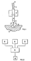
- the arc struck between a welding electrode 10 and workpiece 16 is oscillated within a weld groove 12 in a direction 14 traverse to the longitudinal dimension of the weld groove.
- the arc voltage between the electrode (the edge of the plasma cone, for example) and the side wall at the extremities of oscillation are measured.
- the width of oscillation from a pre- established null at which the side wall voltages are measured is also monitored.
- the null reference for oscillation can then be maintained at any predetermined location along the oscillation path by adjusting the null as a function of the magnitude of the voltage drop between the electrode and the weld groove side wall and the given width of oscillation at which the voltage is measured.
- a plasma arc is struck between a tungsten electrode 22 and the workpiece 16, which is normally grounded.
- the weld puddle in the bottom of the weld groove is purged of air by a stream of inert gas, for example a mixture of argon and helium, which is directed from the torch 10 by and through the nozzle 24.
- the purging gas forms an inert barrier to prevent impurities from being absorbed into the weld metal as it solidifies.
- the weld material is added to the puddle through a separate wire feed system, which is not shown.
- it is desirable to cool the torch and generally water conduits within the torch are employed for this purpose.
- the cabling for supplying the electricity, water and gas to the torch is figuratively illustrated by reference character 18. It should be appreciated that in some applications the separate water, gas and electrical conduits are provided by concentric passages in the cabling.
- tungsten torch 10 is shown coupled to a support bracket 26, which can be reciprocally driven in such a fashion by any one of several commercially available oscillators, which are normally employed for this purpose.
- Other forms of arc oscillation (whether or not implemented through oscillation of the torch) presently used in the art can be similarly employed for this purpose.
- a pivoting oscillator employing a torch support fixture similar to that described in U.S. Patent 2,082,967, issued June 8, 1937.
- a fixture can be oscillated by a stepping motor and the oscillation excursion measurements made in a manner similar to that described in the following embodiment.
- the automatic voltage control system (32) basically monitors the voltage between the tungsten electrode 22 and the bottom of the weld groove 12 and compares that voltage with a preselected voltage. The difference indicated by the comparison is used as an error signal to drive a stepping motor connected to the fixturing 26 to reposition the torch with respect to the bottom of the weld groove in a direction to minimize the error.
- the arc voltage to the bottom of the weld groove is monitored and any deviation from the set point is employed to correct the spacing between the electrode and the bottom of the weld groove.
- automatic voltage control system operation is inactivated during oscillator action to avoid erroneous readings encountered as the arc traverses the weld groove to the side wall at the lateral extensions of oscillation.
- the welding electrode is driven from a constant current source so that voltage fluctuations are not erroneously noted by the automatic voltage control system during its operation. Constant current control is also desirable to assure the integrity of the weldment.
- Oscillation of the welding arc is accomplished by lateral displacement of the torch, as the torch traverses the weld groove, by a cross slide manipulator driven by a stepping motor. Oscillators of this type specifically designed for welding applications are commercially available. Desirably the forward travel of the torch within the weld groove is maintained at a constant rate.
- the oscillator is controlled to move the torch K-1 steps to the right with the automatic voltage control operative for the first K-2 steps; where K-2 is less than K-1; and where the spacing between the tungstens and the bottom of the weld groove is less than the spacing between the tungsten and the side wall of the weld groove at the K-2 lateral displacement; and further where the spacing between the tungsten and the bottom of the weld groove is greater than the spacing between the tungsten and the side wall of the weld groove at the K-1 lateral displacement.
- the arc voltage is sampled a selected multiple number of times, for example eight times, with the automatic voltage control disconnected.
- the voltage reading is supplied by a voltage monitoring circuit 28 coupled between the tungsten electrode electrical connection to the torch 20 and ground.
- the multiple voltage samples are inputted to a microcomputer 34 via an analog-to-digital converter.
- the multiple samples of arc voltage are averaged in the microcomputer, and the result is stored in the memory; the torch is then moved left K-1 steps back to its original lateral position with the automatic voltage control operative in the last K-2 steps, and then K-1 steps further to the left with the automatic voltage control again operative in the first K-2 steps.
- the arc voltage is again sampled a multiple number of times and the average is computed in the microcomputer.
- the torch is next moved K-1 steps to the right returning to its original null position.
- the automatic voltage control is again operative in the last K-2 steps. Simultaneously with the last operation the microcomputer compares the two average arc voltage samples. If the averaged voltage on the right excursion is less than that on the left excursion, the torch is moved K-3 steps to the left, where K-3 is a predetermined number, desirably traversing a small increment. If the average voltage on the right excursion is more than that on the left excursion, the torch is moved K-3 steps to the right. If the two voltages are equal, no correction to lateral travel is made. The process is then again repeated to provide continued accurate positioning of the weld torch within the groove as the torch traverses the weld seam. The accuracy of the voltage measurements can be enhanced by having the microcomputer disregard measurements outside of an anticipated range in computing the averages called for by this invention. A number of such noise rejection techniques are known in the art.
- Block diagram 30 in Figure 2 figuratively represents the oscillator control and monitoring system that provides an output indicative of the width of the lateral excu- sion of the oscillator.
- This output representative of the oscillation width of the torch from a pre- established reference null, is communicated to the microprocessor 34 which connects and disconnects the automatic voltage control stepping motor and lateral manipulator controls during the appropriate portions of the oscillation cycle.
- the microprocessor 34 also provides appropriate output commands to control the arc voltage control positioning system, the width of oscillation and the oscillation null position.
- the lateral correction provided by the tracking system of the invention could also be made proportional to the difference in the two averaged side wall voltages rather than being a fixed number of steps K-3.
- the microprocessor would provide an output proportional to the difference to direct the stepping motor to move an appropriate number of steps.
- a separate stepping motor 36 is figuratively illustrated for accomplishing the lateral displacement of the oscillator manipulator fixture for repositioning the null of oscillation. It should be further appreciated that the stepping oscillator can be replaced with a continuous oscillator with the width of oscillation monitored through an encoder output.
- the automatic voltage control can be inactivated during the lateral search mode, with periods of oscillation alternated with a normal travel mode without oscillation with the automatic voltage control operative; or a dwell period can be programmed between oscillations to accommodate the automatic voltage control operation.
- the arc is programmed to move or step laterally during oscillation until the side wall is sensed by the abrupt change in voltage experienced when the arc shifts to the weld groove side wall.
- the microprocessor can then determine the number of steps taken in each direction of lateral displacement of oscillation before the change in voltage is sensed, compare the number of steps taken on either side of the null of oscillation and make the appropriate correction to the lateral displacement to locate the welding electrode at a programmed position within the weld groove.
- the null would be programm- ably situated along the centreline of the groove.
- a preselected offset can be added or subtracted from either measured voltage, or to the result of the comparision of voltages; or, alternately, where the voltage measured determines the width of oscillation in each direction, a preselected offset can be added to the comparison of the lateral excursion widths.
- a reference measurement can be taken and either the measured voltage or the width of oscillation (measured on the side of the groove within which the oscillation is implemented) whichever embodiment is used, can be compared to the reference to determine whether the arc should be repositioned.
- the single sidewall sensing mode operates in the same manner as described above except that all samples are taken either on the right extremity of oscillation or the left extremity of oscillation, but not both. For example, suppose the samples are taken on the left extremity. Then successive averaged samples on the left extremity are compared for corrective action rather than samples at the left and right extremity. This means that samples are taken once per cycle of oscillation (on the left side) rather than twice per cycle of oscillation (on left and right sides).
- This mode of operation you can track one side of the joint.
- This mode is also preferable for fillet welds (for example) formed by butting one member against another at right angles.
- Single sidewall sensing may be employed as an alternate tracking method during full width oscillation as well.
- the tracking systems of this invention are thus extremely flexible and amenable to programmed operation, in that a number of references can be stored in the microprocessor and applied at varying points during a given pass, or between passes. It should be appreciated that the flexibility of the system of this invention will enable an operator to manually control the torch positioning and oscillating parameters until an optimum weld puddle is established. Then the operator can continue the welding pass, or implement subsequent passes under the established optimum operating conditions, automatically, through the programmed closed loop operation of this invention.
- a further improvement is provided by monitoring the voltage between the welding electrode and the bottom of the weld groove over a plurality of oscillations, for example eight, and averaging the monitored voltage samples prior to being compared to the reference to establish whether any correction is required by the automatic voltage control system.
- the arc voltage is monitored each oscillation cycle, however, correction is only applied after a plurality of such cycles.
- the automatic voltage control spacing correction is made only during the period of the oscillation cycle that the automatic voltage control voltage monitoring is performed so that the movement into or away from the weld groove caused by the automatic voltage control does not affect the side wall voltage readings.
- oscillation variables and monitored parameters controlled by this invention can also be processed by a hard wired circuit arrangement similar to the circuit illustrated in Figure 5 of U.S. Patent No. 4,308,098 where the economics of microprocessor prove not to be feasible.
- the foregoing circuit is capable of averaging and storing the monitored values as required by this invention and can be used in connection with comparators and interface circuitry to provide the necessary outputs to control the varius operations of this invention.
Landscapes
- Engineering & Computer Science (AREA)
- Physics & Mathematics (AREA)
- Plasma & Fusion (AREA)
- Mechanical Engineering (AREA)
- Arc Welding In General (AREA)
- Butt Welding And Welding Of Specific Article (AREA)
- Arc Welding Control (AREA)
Applications Claiming Priority (2)
| Application Number | Priority Date | Filing Date | Title |
|---|---|---|---|
| US06/054,517 US4336440A (en) | 1979-07-03 | 1979-07-03 | Weld tracking/electronic arc sensing system |
| US54517 | 1979-07-03 |
Publications (3)
| Publication Number | Publication Date |
|---|---|
| EP0021856A1 EP0021856A1 (en) | 1981-01-07 |
| EP0021856B1 EP0021856B1 (en) | 1983-07-20 |
| EP0021856B2 true EP0021856B2 (en) | 1990-08-22 |
Family
ID=21991641
Family Applications (1)
| Application Number | Title | Priority Date | Filing Date |
|---|---|---|---|
| EP80302260A Expired EP0021856B2 (en) | 1979-07-03 | 1980-07-03 | Weld electrode tracking system |
Country Status (8)
| Country | Link |
|---|---|
| US (1) | US4336440A (en:Method) |
| EP (1) | EP0021856B2 (en:Method) |
| JP (2) | JPS5611184A (en:Method) |
| KR (1) | KR880001472B1 (en:Method) |
| DE (1) | DE3064252D1 (en:Method) |
| ES (1) | ES8105606A1 (en:Method) |
| FR (1) | FR2460746A1 (en:Method) |
| IT (1) | IT1132146B (en:Method) |
Families Citing this family (22)
| Publication number | Priority date | Publication date | Assignee | Title |
|---|---|---|---|---|
| US4446353A (en) * | 1980-01-24 | 1984-05-01 | Crutcher Resources Corporation | Center tracking welder unit with floating reference |
| JPS5877775A (ja) * | 1981-10-07 | 1983-05-11 | Yaskawa Electric Mfg Co Ltd | 溶接ロボツトの制御方式 |
| US4495400A (en) * | 1982-04-26 | 1985-01-22 | Crutcher Resources Corporation | Method and apparatus for positioning a welding torch in automatic electric welding |
| US4477713A (en) * | 1982-07-09 | 1984-10-16 | Crc Welding Systems, Inc. | Sidewall-matching adaptive control system for welding |
| US4531192A (en) * | 1982-09-23 | 1985-07-23 | Crc Welding Systems, Inc. | Apparatus and method for sensing a workpiece with an electrical arc |
| US4538233A (en) * | 1982-10-19 | 1985-08-27 | Cincinnati Milacron Inc. | Apparatus and method for oscillatory motion control |
| US4532408A (en) * | 1982-10-22 | 1985-07-30 | The Ohio State University | Apparatus and method for viewing molten pools in arc welding |
| US4595820A (en) * | 1982-10-22 | 1986-06-17 | The Ohio State University | Apparatus and methods for controlling a welding process |
| US4635206A (en) * | 1984-10-15 | 1987-01-06 | Cincinnati Milacron Inc. | Method and apparatus for oscillating a tool carried by a manipulator |
| GB2180183B (en) * | 1985-07-31 | 1989-09-06 | Mitsubishi Electric Corp | Automatic welding machine correcting for a variable groove width |
| GB2345016B (en) | 1998-12-24 | 2003-04-02 | Saipem Spa | Method and apparatus for welding pipes together |
| GB9828727D0 (en) | 1998-12-24 | 1999-02-17 | Saipem Spa | Apparatus and method for welding pipes together |
| TW445192B (en) | 1999-04-12 | 2001-07-11 | Tri Tool Inc | Control method and apparatus for an arc welding system |
| DE69925043D1 (de) | 1999-07-21 | 2005-06-02 | Saipem Spa | Verbesserungen zur verlegung von unterwasserrohren |
| ATE349293T1 (de) | 2000-10-24 | 2007-01-15 | Saipem Spa | Verfahren und vorrichtung zum verschweissen von rohren |
| GB2373750A (en) | 2001-03-27 | 2002-10-02 | Saipem Spa | Welding pipe-in-pipe pipelines |
| WO2007079041A2 (en) * | 2005-12-30 | 2007-07-12 | Roger Hirsch | Resistance welding machine pinch point safety sensor |
| NL1037804C2 (nl) * | 2010-03-12 | 2011-09-13 | Richard Andr Zurburg | Werkwijze en inrichting voor het assembleren van buizen en fittingen. |
| JP5538181B2 (ja) | 2010-10-26 | 2014-07-02 | 川崎重工業株式会社 | アーク溶接の制御システムおよび制御方法 |
| US10807179B2 (en) * | 2017-02-17 | 2020-10-20 | General Electric Company | Method of build-up welding |
| JP6763818B2 (ja) * | 2017-04-20 | 2020-09-30 | 株式会社ダイヘン | アーク溶接装置及びアーク溶接方法 |
| CN110653463B (zh) * | 2018-06-29 | 2021-09-21 | 南京理工大学 | 一种实时测量螺柱焊过程中偏弧的方法 |
Family Cites Families (14)
| Publication number | Priority date | Publication date | Assignee | Title |
|---|---|---|---|---|
| US2082967A (en) * | 1935-08-16 | 1937-06-08 | Air Reduction | Apparatus for cutting swinging bevels |
| US3646309A (en) * | 1971-01-26 | 1972-02-29 | Atomic Energy Commission | Self-adaptive welding torch controller |
| JPS52100352A (en) * | 1976-02-20 | 1977-08-23 | Matsushita Electric Industrial Co Ltd | Apparatus for following weld line |
| JPS529657A (en) * | 1975-07-14 | 1977-01-25 | Matsushita Electric Industrial Co Ltd | Groove line follow up device |
| US4350868A (en) * | 1975-07-14 | 1982-09-21 | Matsushita Electric Industrial Co., Ltd. | Follow-up control apparatus for controlling the movement of a welding weaving device |
| DE2546894A1 (de) * | 1975-10-20 | 1977-04-28 | Puschner Peter | Verfahren zur steuerung maschineller schweissvorgaenge |
| CH611824A5 (en:Method) * | 1975-07-25 | 1979-06-29 | Puschner Peter | |
| US4188525A (en) * | 1976-02-03 | 1980-02-12 | Merrick Welding International | Welding torch oscillation apparatus |
| IT1058816B (it) * | 1976-04-13 | 1982-05-10 | 2 A Spa | Procedimento per fissare la ..spirale.. ad un nastro tessuto per chiusure lampo.. nastro ottenuto mediante tale procedimento.. e telaio senza navetta per la sua fabbricazione |
| US4095077A (en) * | 1976-06-25 | 1978-06-13 | Westinghouse Electric Corp. | Automatic hot filler wire welding method and apparatus |
| US4151395A (en) * | 1976-07-06 | 1979-04-24 | CRC-Crose, International, Inc. | Method and apparatus for electric arc and analogous welding under precision control |
| DE2645788A1 (de) * | 1976-10-09 | 1978-04-13 | Drews Paul | Mechanisierte schweissanlage |
| JPS5382637A (en) * | 1976-12-28 | 1978-07-21 | Matsushita Electric Industrial Co Ltd | Followwup control method of welding wire in unconsumed electrode arc welding method and its device |
| DE2715644A1 (de) * | 1977-04-07 | 1978-10-12 | Drews Paul Prof Dr Ing | Fuehrungssystem der elektrode einer lichtbogenschweissmaschine in schweissspaltmitte |
-
1979
- 1979-07-03 US US06/054,517 patent/US4336440A/en not_active Expired - Lifetime
-
1980
- 1980-07-01 IT IT23154/80A patent/IT1132146B/it active
- 1980-07-02 FR FR8014730A patent/FR2460746A1/fr active Granted
- 1980-07-03 KR KR1019800002639A patent/KR880001472B1/ko not_active Expired
- 1980-07-03 EP EP80302260A patent/EP0021856B2/en not_active Expired
- 1980-07-03 DE DE8080302260T patent/DE3064252D1/de not_active Expired
- 1980-07-03 JP JP9002980A patent/JPS5611184A/ja active Pending
- 1980-07-03 ES ES493088A patent/ES8105606A1/es not_active Expired
-
1983
- 1983-07-20 JP JP1983111589U patent/JPS5949470U/ja active Pending
Also Published As
| Publication number | Publication date |
|---|---|
| ES493088A0 (es) | 1981-06-16 |
| FR2460746A1 (fr) | 1981-01-30 |
| EP0021856B1 (en) | 1983-07-20 |
| JPS5949470U (ja) | 1984-04-02 |
| ES8105606A1 (es) | 1981-06-16 |
| KR880001472B1 (ko) | 1988-08-13 |
| EP0021856A1 (en) | 1981-01-07 |
| IT8023154A0 (it) | 1980-07-01 |
| DE3064252D1 (en) | 1983-08-25 |
| FR2460746B1 (en:Method) | 1985-01-04 |
| JPS5611184A (en) | 1981-02-04 |
| KR830003270A (ko) | 1983-06-18 |
| IT1132146B (it) | 1986-06-25 |
| US4336440A (en) | 1982-06-22 |
Similar Documents
| Publication | Publication Date | Title |
|---|---|---|
| EP0021856B2 (en) | Weld electrode tracking system | |
| EP0201641B1 (en) | Welding torch position detection system and method | |
| US4525619A (en) | Automatic weld line following method | |
| US9862050B2 (en) | Auto steering in a weld joint | |
| US6927360B2 (en) | Method for continuously regulating or tracking a position of a welding torch or a welding head | |
| US5510595A (en) | Machine for automatic in situ welding according to a curvilinear section profile and having programmable extrapolation control | |
| CN108883487B (zh) | 电弧仿形焊接方法以及电弧仿形焊接装置 | |
| DE3274728D1 (en) | A method controlling an arc welding torch of a welding robot | |
| JP3205264U (ja) | 溶接継手において自動アークステアリングと共にアーク溶接を行う方法及びアーク溶接システム | |
| US5066847A (en) | Automatic welding machine path correction method | |
| US6150631A (en) | Method of detecting root gap and arc welding method using the former | |
| EP0198090A1 (en) | System for correcting a path of an automatic welding machine | |
| JPH1058238A (ja) | 放電切断方法及び装置 | |
| JPH0825024B2 (ja) | 自動溶接装置 | |
| JPH0263684A (ja) | 溶接線倣い方法 | |
| JPH064194B2 (ja) | アーク溶接ロボットによる溶接方法 | |
| JP3115206B2 (ja) | アークセンサ装置 | |
| JPS6215317B2 (en:Method) | ||
| JPH0112591B2 (en:Method) | ||
| JPH0426942B2 (en:Method) | ||
| JPH0420711B2 (en:Method) | ||
| JPH0328261B2 (en:Method) | ||
| JPS60130471A (ja) | 溶接線追従方法および装置 | |
| JPH0999369A (ja) | アークセンサ装置 | |
| JPH09150271A (ja) | アークセンサ装置 |
Legal Events
| Date | Code | Title | Description |
|---|---|---|---|
| PUAI | Public reference made under article 153(3) epc to a published international application that has entered the european phase |
Free format text: ORIGINAL CODE: 0009012 |
|
| AK | Designated contracting states |
Designated state(s): BE DE GB SE |
|
| 17P | Request for examination filed |
Effective date: 19810701 |
|
| GRAA | (expected) grant |
Free format text: ORIGINAL CODE: 0009210 |
|
| AK | Designated contracting states |
Designated state(s): BE DE GB SE |
|
| REF | Corresponds to: |
Ref document number: 3064252 Country of ref document: DE Date of ref document: 19830825 |
|
| PLBI | Opposition filed |
Free format text: ORIGINAL CODE: 0009260 |
|
| 26 | Opposition filed |
Opponent name: SIEMENS AKTIENGESELLSCHAFT, BERLIN UND MUENCHEN Effective date: 19840416 |
|
| PUAH | Patent maintained in amended form |
Free format text: ORIGINAL CODE: 0009272 |
|
| STAA | Information on the status of an ep patent application or granted ep patent |
Free format text: STATUS: PATENT MAINTAINED AS AMENDED |
|
| 27A | Patent maintained in amended form |
Effective date: 19900822 |
|
| AK | Designated contracting states |
Kind code of ref document: B2 Designated state(s): BE DE GB SE |
|
| EAL | Se: european patent in force in sweden |
Ref document number: 80302260.7 |
|
| PGFP | Annual fee paid to national office [announced via postgrant information from national office to epo] |
Ref country code: GB Payment date: 19960617 Year of fee payment: 17 |
|
| PGFP | Annual fee paid to national office [announced via postgrant information from national office to epo] |
Ref country code: SE Payment date: 19960624 Year of fee payment: 17 |
|
| PGFP | Annual fee paid to national office [announced via postgrant information from national office to epo] |
Ref country code: DE Payment date: 19960730 Year of fee payment: 17 |
|
| PGFP | Annual fee paid to national office [announced via postgrant information from national office to epo] |
Ref country code: BE Payment date: 19960806 Year of fee payment: 17 |
|
| PG25 | Lapsed in a contracting state [announced via postgrant information from national office to epo] |
Ref country code: GB Free format text: LAPSE BECAUSE OF NON-PAYMENT OF DUE FEES Effective date: 19970703 |
|
| PG25 | Lapsed in a contracting state [announced via postgrant information from national office to epo] |
Ref country code: SE Effective date: 19970704 |
|
| PG25 | Lapsed in a contracting state [announced via postgrant information from national office to epo] |
Ref country code: BE Free format text: LAPSE BECAUSE OF NON-PAYMENT OF DUE FEES Effective date: 19970731 |
|
| BERE | Be: lapsed |
Owner name: WESTINGHOUSE ELECTRIC CORP. Effective date: 19970731 |
|
| GBPC | Gb: european patent ceased through non-payment of renewal fee |
Effective date: 19970703 |
|
| PG25 | Lapsed in a contracting state [announced via postgrant information from national office to epo] |
Ref country code: DE Free format text: LAPSE BECAUSE OF NON-PAYMENT OF DUE FEES Effective date: 19980401 |
|
| EUG | Se: european patent has lapsed |
Ref document number: 80302260.7 |