EP0198090A1 - System for correcting a path of an automatic welding machine - Google Patents
System for correcting a path of an automatic welding machine Download PDFInfo
- Publication number
- EP0198090A1 EP0198090A1 EP85904880A EP85904880A EP0198090A1 EP 0198090 A1 EP0198090 A1 EP 0198090A1 EP 85904880 A EP85904880 A EP 85904880A EP 85904880 A EP85904880 A EP 85904880A EP 0198090 A1 EP0198090 A1 EP 0198090A1
- Authority
- EP
- European Patent Office
- Prior art keywords
- welding
- torch
- weaving
- current
- path
- Prior art date
- Legal status (The legal status is an assumption and is not a legal conclusion. Google has not performed a legal analysis and makes no representation as to the accuracy of the status listed.)
- Granted
Links
Images


Classifications
-
- B—PERFORMING OPERATIONS; TRANSPORTING
- B23—MACHINE TOOLS; METAL-WORKING NOT OTHERWISE PROVIDED FOR
- B23K—SOLDERING OR UNSOLDERING; WELDING; CLADDING OR PLATING BY SOLDERING OR WELDING; CUTTING BY APPLYING HEAT LOCALLY, e.g. FLAME CUTTING; WORKING BY LASER BEAM
- B23K9/00—Arc welding or cutting
- B23K9/12—Automatic feeding or moving of electrodes or work for spot or seam welding or cutting
- B23K9/127—Means for tracking lines during arc welding or cutting
Definitions
- This invention relates to an automatic welding machine path correction system and, more particularly, to a path correction system in an automatic welding machine for performing welding while weaving a welding torch left and right with respect to a welding line.
- An automatic welding machine performs welding by impressing a voltage across a wire and a workpiece to produce an arc at the tip of the wire, and moving the wire tip along a welding path while the wire is successively paid out in small increments.
- Fig. 8 is a schematic view of such a welding machine.
- WR denotes the wire, which is paid out in small increments in the direction of the arrow by feed rollers FR so that its tip protrudes from the end of a torch TC via a guide member GB, with the amount by which the wire is fed being limited in such a manner that the tip comes to occupy a position spaced a predetermined distance from the surface of the workpiece WK.
- a welding power supply PS which impresses the voltage across the wire WR and the workpiece WK, generates a continuous high-voltage at a predetermined period.
- the plus side is applied to the wire WR through the guide member GB, and the minus side is connected to the workpiece WK.
- C0 2 gas from a gas supply unit which is not shown, is supplied by a C0 2 source. Welding is performed while the C0 2 gas is jetted toward the portion being welded, thereby preventing oxidation of the welded portion.
- the robot control unit moves the torch TC upon calculating the extreme points to the left and right from starting and end points, which have been taught, as well as amplitude and frequency.
- welding cannot be performed accurately at the predetermined location of the workpiece when the torch TC is moved based on the taught points. Accordingly, as shown in Fig.
- the conventional practice is to monitor the value of the integral of the welding current and effect a path correction upon comparing the integral value with a reference value when the difference between an integral value prevailing at a leftward swing and an integral value prevailing at a rightward swing in one cycle exceeds a stipulated value.
- An object of the present invention is to provide an automatic welding machine path correction system capable of correcting a welding path smoothly and accurately irrespective of the welding mode.
- a path correction method in an automatic welding machine which performs welding while weaving a welding torch to the left and right of a welding line, which method has a first step of calculating interpolated points of a weaving path, which has a trapezoidal shape in a half cycle, from a given starting point, end point, amplitude and frequency, a second step of moving the torch along the path calculated in the first step and sensing welding current when the torch is operating parallel to the welding line (namely in the vicinity of the left and right extremes of the weaving pattern), and a third step of correcting the weaving path based on a difference between welding currents at left and right extreme points of weaving sensed in the second step.
- a path correction system of an automatic welding machine which performs welding while weaving a welding torch to the left and right of a welding line
- which system has a torch for welding a workpiece, a welding power supply for supplying the torch with current, current sensing means for sensing the welding current supplied to the torch by the welding power supply, means for causing the current sensing means to sense welding current supplied to the torch by the welding power supply at left and right positions of the torch when weaving is performed, and means for subtracting the left and right welding current values and correcting, based on the difference value, the center of the weaving pattern traversed by the torch.
- the present invention makes it possible to accurately sense the extreme points of the weaving pattern and to correct the welding path smoothly irrespective of the welding mode.
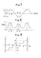
- Fig. 1 is a view for describing a weaving pattern used in the present invention
- Fig. 2 is a view for describing a change in welding current corresponding to the weaving pattern shown in Fig. 1
- Fig. 3 is a view for describing the manner in which a correction amount is decided
- Fig. 4 is a block diagram of a welding robot for practicing the present invention
- Fig. 5 is a flowchart for describing the operation of the present invention
- Fig. 6 is a view for describing a conventional weaving pattern
- Fig. 7 is a view for describing a conventional manner of correcting a path
- Fig. 8 is a schematic view showing the construction of a welding machine.
- the present invention monitors welding current to correct weaving in such a manner that the center of weaving conforms to the center (welding line CT) of the beveled portion.
- the amount of the correction is reflected in the path calculation of the next cycle, whereby the correction is made during the next cycle.
- the path correction is performed based on the symmetry of a change in welding current when welding motion is made to the left and right during weaving. Accordingly, the beveled shape is formed so as to be symmetrical within the range in which the weaving motion is made.
- the welding current has a differential value (rate of change) of a certain magnitude up to a point 1.
- the torch TC begins to move along the side wall of the workpiece, namely when the torch is located between points Q) and 2 on the path parallel to the welding line, there is no change in the welding current and, hence, the differential value is zero.
- a control unit is capable of sensing the welding current at the extremes of the weaving pattern by taking a sampling of values at the extremes.
- the detection of the welding current at the extremes of the weaving pattern need not rely upon sampled values as mentioned above but can be accomplished by obtaining the average value of welding currents from extreme point 1 to extreme point 2 on the path, which lies parallel to the welding line, where the amount of change in the welding current is zero.
- CE represent a current error for determining the amount of correction
- RD the amount of welding current sensed on the right side of the welding line
- LD the amount of welding current sensed on the left side of the welding line.
- An amount of bias to one side can be allowed for when necessary. For example, if it is desired to allow for an amount of bias on the right side, then we will have In this way it is possible to deal with a workpiece having left-right asymmetry.
- Fig. 3 is a view for describing the manner in which the amount of path correction is decided.
- a, b, and c denote values of the abovementioned current error CE
- 1 1 . 1 2 represent designated values of parameters serving as the basis of a correction value.
- the control unit will correct the center of weaving by a correction amount 1 1 , namely 0.1 mm.
- Fig. 4 is a block diagram schematically illustrating a welding robot.
- numeral 1 denotes a welding machine
- numeral 2 represents a welding robot having a hand which grasps the torch TC of the welding machine and moves the torch TC along the workpiece WK in accordance with taught data.
- Numeral 3 denotes a numerical control unit for controlling the welding machine 1 and the welding robot 2.
- Numeral 4 represents a welding power supply for supplying the torch TC with a welding current.
- the numerical control unit 3 has a central processor (CPU) 31 for controlling the overall numerical controlunit and for executing processing, a read-only memory (ROM) 31 storing a control program, a random-access memory (RAM) 32 for temporarily storing various data such as the data the robot has been taught, an operator's panel 33 for entering various welding conditions and for teaching the welding robot as well as a welding activity, a display device 34 for displaying the present position of the torch TC, a program list and data, and an digital/analog converter 35 for converting digital command values received from the CPU 31 into analog command values and for delivering these analog command values to the welding machine 1.
- CPU central processor
- ROM read-only memory
- RAM random-access memory
- the welding current supplied from the welding machine I to the torch TC is measured by a current sensor la, which applies the measured value to the numerical control unit 3.
- the welding robot has been taught the necessary data, such as welding line (CT) position data and a weaving command format for commanding a weaving operation, by means of a teaching operation, that initial motion of the torch TC has ended, that the torch TC is at a point P in Fig. 1 in the course of operation, and that the torch is to be moved from this position.
- CT welding line
- the torch TC starts to be moved from point P to the left side. This motion is effected by using two items of data, namely a frequency f and an amplitude value, commanded earlier in the weaving command format [step (1)]. Meanwhile, the welding current supplied to the torch TC from the welding machine 1 is constantly being sensed by the current sensor la, which sends the resulting signal to the numerical control unit 3. Motion of the torch TC is monitored at all times by the CPU 31. When the torch TC reaches the positions 1 and 2 in Figs. 1 and 2, between which positions the change in welding current ceases, the current value LD prevailing at this time is stored in the RAM 33 [steps (2) and (3)]. It should be noted that monitoring the cessation of the change in current can be performed at the position of the torch TC, as described above, or by differentiating the welding current.
- the torch moves to the right side of the welding line CT [step (4)].
- the welding current supplied to the torch TC by the welding machine 1 is constantly sensed by the current sensor la, whose output signal is applied to the numerical control unit 3, and motion of the torch TC is constantly monitored by the CPU 31.
- the current value RD prevailing at this time is stored in the RAM 33 [steps (5) and (6)].
- the calculation is performed during one cycle of the welding operation [step (7)]. If the result of the calculation is zero, i.e. the error current CE has a value of zero, there is no left-right positional correction with respect to the center of the weaving pattern along which the torch TC advances. If the result of the calculation is a positive (+) value, the position of the center of the weaving pattern along which the torch TC advances is too far to the left. In the next cycle of the welding operation, therefore, the position is corrected to the right side by the magnitude of the current error CE.
- the position of the center of the weaving pattern along which the torch TC advances is too far to the right and, hence, in the next cycle of the welding operation, the position is corrected to the left side by the magnitude of the current error CE [step (8)].
- the present invention monitors the amount of change in the welding current at the time of weaving, senses the welding current at the left and right extremes where the amount of change is zero, and corrects the weaving path based on the difference between the current values at the left and right extremes. Accordingly, the extreme points of the weaving pattern can be accurately sensed and the welding path can be corrected smoothly irrespective of the welding mode. This makes it possible to reduce the labor and energy involved in the welding operation and to enhance both the efficiency and reliability of the operation.
- the automatic welding machine path correction system enables the path of a welding torch to be corrected automatically and therefore is well-suited for application to a welding robot having a soft weaving function.
Abstract
Description
- This invention relates to an automatic welding machine path correction system and, more particularly, to a path correction system in an automatic welding machine for performing welding while weaving a welding torch left and right with respect to a welding line.
- An automatic welding machine performs welding by impressing a voltage across a wire and a workpiece to produce an arc at the tip of the wire, and moving the wire tip along a welding path while the wire is successively paid out in small increments. Fig. 8 is a schematic view of such a welding machine. In the Figure, WR denotes the wire, which is paid out in small increments in the direction of the arrow by feed rollers FR so that its tip protrudes from the end of a torch TC via a guide member GB, with the amount by which the wire is fed being limited in such a manner that the tip comes to occupy a position spaced a predetermined distance from the surface of the workpiece WK. A welding power supply PS, which impresses the voltage across the wire WR and the workpiece WK, generates a continuous high-voltage at a predetermined period. The plus side is applied to the wire WR through the guide member GB, and the minus side is connected to the workpiece WK. In the torch TC, C02 gas from a gas supply unit, which is not shown, is supplied by a C02 source. Welding is performed while the C02 gas is jetted toward the portion being welded, thereby preventing oxidation of the welded portion.
- When a high voltage is generated continuously by the welding power supply PS while the C02 gas is fed from the gas supply unit, not shown, and the wire WR is paid out in small increments in the welding machine having the above construction, an arc is produced at the tip of the wire and both the wire and the portion being welded are melted to weld the fused portions of the workpiece together. It has recently become possible to perform such a welding operation automatically by robot. Specifically, the torch TC of the welding machine is grasped by a robot, which is caused to move the torch (the tip of the wire) along a welding path to weld the workpiece.
- When weaving is performed to the left and right of a cutting line CT, as shown in Fig. 6, the robot control unit moves the torch TC upon calculating the extreme points to the left and right from starting and end points, which have been taught, as well as amplitude and frequency. However, in cases where there are differences in the machined precision of the workpiece or where there is a shift in the attached position, welding cannot be performed accurately at the predetermined location of the workpiece when the torch TC is moved based on the taught points. Accordingly, as shown in Fig. 7, the conventional practice is to monitor the value of the integral of the welding current and effect a path correction upon comparing the integral value with a reference value when the difference between an integral value prevailing at a leftward swing and an integral value prevailing at a rightward swing in one cycle exceeds a stipulated value.
- With this method of correcting the path based on the integrated value of the welding current, sensitivity is very low, especially when the current is small, and the method is not suited to some welding modes as far as the welding characteristics are concerned.
- An object of the present invention is to provide an automatic welding machine path correction system capable of correcting a welding path smoothly and accurately irrespective of the welding mode.
- According to the present invention, there is provided a path correction method in an automatic welding machine which performs welding while weaving a welding torch to the left and right of a welding line, which method has a first step of calculating interpolated points of a weaving path, which has a trapezoidal shape in a half cycle, from a given starting point, end point, amplitude and frequency, a second step of moving the torch along the path calculated in the first step and sensing welding current when the torch is operating parallel to the welding line (namely in the vicinity of the left and right extremes of the weaving pattern), and a third step of correcting the weaving path based on a difference between welding currents at left and right extreme points of weaving sensed in the second step.
- Further, according to the present invention, there is provided a path correction system of an automatic welding machine which performs welding while weaving a welding torch to the left and right of a welding line, which system has a torch for welding a workpiece, a welding power supply for supplying the torch with current, current sensing means for sensing the welding current supplied to the torch by the welding power supply, means for causing the current sensing means to sense welding current supplied to the torch by the welding power supply at left and right positions of the torch when weaving is performed, and means for subtracting the left and right welding current values and correcting, based on the difference value, the center of the weaving pattern traversed by the torch.
- The present invention makes it possible to accurately sense the extreme points of the weaving pattern and to correct the welding path smoothly irrespective of the welding mode.
- Fig. 1 is a view for describing a weaving pattern used in the present invention, Fig. 2 is a view for describing a change in welding current corresponding to the weaving pattern shown in Fig. 1, Fig. 3 is a view for describing the manner in which a correction amount is decided, Fig. 4 is a block diagram of a welding robot for practicing the present invention, Fig. 5 is a flowchart for describing the operation of the present invention, Fig. 6 is a view for describing a conventional weaving pattern, Fig. 7 is a view for describing a conventional manner of correcting a path, and Fig. 8 is a schematic view showing the construction of a welding machine.
- An embodiment of the present invention will now be described in detail with reference to Figs. 1 through 3.
- In a case where a V- or L-shaped beveled portion is to be welded by a weaving pattern, the present invention monitors welding current to correct weaving in such a manner that the center of weaving conforms to the center (welding line CT) of the beveled portion. When it is judged that a path correction is necessary, the amount of the correction is reflected in the path calculation of the next cycle, whereby the correction is made during the next cycle.
- In order to effect the weaving path correction, a weaving frequency higher than 0.4 Hz is required, and the path correction is performed based on the symmetry of a change in welding current when welding motion is made to the left and right during weaving. Accordingly, the beveled shape is formed so as to be symmetrical within the range in which the weaving motion is made.
- Fig. 1 is a view for describing a weaving pattern used in the present invention. The weaving pattern defines a trapezoidal pattern having a path whose left and right extremes lie parallel to the welding line.
- Fig. 2 is a view for describing a change in welding current corresponding to the weaving pattern shown in Fig. 1.
- As is evident from Fig. 2, the welding current has a differential value (rate of change) of a certain magnitude up to a
point ①. However, when the torch TC begins to move along the side wall of the workpiece, namely when the torch is located between points Q) and ② on the path parallel to the welding line, there is no change in the welding current and, hence, the differential value is zero. - A control unit is capable of sensing the welding current at the extremes of the weaving pattern by taking a sampling of values at the extremes. Alternatively, the detection of the welding current at the extremes of the weaving pattern need not rely upon sampled values as mentioned above but can be accomplished by obtaining the average value of welding currents from
extreme point ① toextreme point ② on the path, which lies parallel to the welding line, where the amount of change in the welding current is zero. - Let us now describe a welding path correction.
- Let CE represent a current error for determining the amount of correction, RD the amount of welding current sensed on the right side of the welding line, and LD the amount of welding current sensed on the left side of the welding line. In general, then, we will have

- In other words, in order to effect a path correction, it is necessary to constantly monitor the symmetry of the change in the welding current when welding motion takes place to the left and right at the time of weaving.
- An amount of bias to one side can be allowed for when necessary. For example, if it is desired to allow for an amount of bias on the right side, then we will have

- Determining the amount of path correction will be described next. Fig. 3 is a view for describing the manner in which the amount of path correction is decided. In the Figure, a, b, and c denote values of the abovementioned current error CE, and 11. 12 represent designated values of parameters serving as the basis of a correction value. Here it is appropriate to set changes in the current error value CE to steps of e.g. 0.1 A, and to set the parameter designation values, which serve as the basis of a correction value, to steps of 0.1 mm.
- Accordingly, if the current error CE is a, namely 0.1 A, then the control unit will correct the center of weaving by a
correction amount 11, namely 0.1 mm. - Note that when the current error CE exceeds +0.3 A, an alarm is issued and the control unit stops the welding operation. In other words, if the current error becomes too large, a path correction cannot be made in a normal manner. This is indicated by an alarm and the welding operation is halted.
- A welding robot for practicing the present invention will now be described in brief.
- Fig. 4 is a block diagram schematically illustrating a welding robot. In the Figure,
numeral 1 denotes a welding machine, andnumeral 2 represents a welding robot having a hand which grasps the torch TC of the welding machine and moves the torch TC along the workpiece WK in accordance with taught data. Numeral 3 denotes a numerical control unit for controlling thewelding machine 1 and thewelding robot 2.Numeral 4 represents a welding power supply for supplying the torch TC with a welding current. Thenumerical control unit 3 has a central processor (CPU) 31 for controlling the overall numerical controlunit and for executing processing, a read-only memory (ROM) 31 storing a control program, a random-access memory (RAM) 32 for temporarily storing various data such as the data the robot has been taught, an operator'spanel 33 for entering various welding conditions and for teaching the welding robot as well as a welding activity, adisplay device 34 for displaying the present position of the torch TC, a program list and data, and an digital/analog converter 35 for converting digital command values received from theCPU 31 into analog command values and for delivering these analog command values to thewelding machine 1. - It should be noted that the welding current supplied from the welding machine I to the torch TC is measured by a current sensor la, which applies the measured value to the
numerical control unit 3. - The operation of the invention will now be described.using the flowchart shown in Fig. 5.
- Let us assume that, prior to the execution of welding, the welding robot has been taught the necessary data, such as welding line (CT) position data and a weaving command format for commanding a weaving operation, by means of a teaching operation, that initial motion of the torch TC has ended, that the torch TC is at a point P in Fig. 1 in the course of operation, and that the torch is to be moved from this position.
- The torch TC starts to be moved from point P to the left side. This motion is effected by using two items of data, namely a frequency f and an amplitude value, commanded earlier in the weaving command format [step (1)]. Meanwhile, the welding current supplied to the torch TC from the
welding machine 1 is constantly being sensed by the current sensor la, which sends the resulting signal to thenumerical control unit 3. Motion of the torch TC is monitored at all times by theCPU 31. When the torch TC reaches thepositions - As the movement of the torch TC proceeds, the torch moves to the right side of the welding line CT [step (4)]. In the meantime, however, the welding current supplied to the torch TC by the
welding machine 1 is constantly sensed by the current sensor la, whose output signal is applied to thenumerical control unit 3, and motion of the torch TC is constantly monitored by theCPU 31. When the torch TC reaches the positions (3) and (4) in Figs. 1 and 2, between which positions the change in welding current ceases, the current value RD prevailing at this time is stored in the RAM 33 [steps (5) and (6)]. - The calculation

- If the result of the calculation is a negative (-) value, the position of the center of the weaving pattern along which the torch TC advances is too far to the right and, hence, in the next cycle of the welding operation, the position is corrected to the left side by the magnitude of the current error CE [step (8)].
- Thus, as set forth above, the present invention monitors the amount of change in the welding current at the time of weaving, senses the welding current at the left and right extremes where the amount of change is zero, and corrects the weaving path based on the difference between the current values at the left and right extremes. Accordingly, the extreme points of the weaving pattern can be accurately sensed and the welding path can be corrected smoothly irrespective of the welding mode. This makes it possible to reduce the labor and energy involved in the welding operation and to enhance both the efficiency and reliability of the operation.
- Though the present invention has been described based on an embodiment, the invention is not limited to this embodiment but can be modified in various ways in accordance with the gist of the present invention, such modifications being within the scope of the invention.
- As described above, the automatic welding machine path correction system according to the present invention enables the path of a welding torch to be corrected automatically and therefore is well-suited for application to a welding robot having a soft weaving function.
Claims (5)
Applications Claiming Priority (2)
| Application Number | Priority Date | Filing Date | Title |
|---|---|---|---|
| JP209336/84 | 1984-10-05 | ||
| JP59209336A JPS6188975A (en) | 1984-10-05 | 1984-10-05 | Path correcting system for automatic welder |
Publications (3)
| Publication Number | Publication Date |
|---|---|
| EP0198090A1 true EP0198090A1 (en) | 1986-10-22 |
| EP0198090A4 EP0198090A4 (en) | 1988-06-27 |
| EP0198090B1 EP0198090B1 (en) | 1992-05-20 |
Family
ID=16571259
Family Applications (1)
| Application Number | Title | Priority Date | Filing Date |
|---|---|---|---|
| EP85904880A Expired - Lifetime EP0198090B1 (en) | 1984-10-05 | 1985-10-04 | System for correcting a path of an automatic welding machine |
Country Status (5)
| Country | Link |
|---|---|
| US (1) | US4785155A (en) |
| EP (1) | EP0198090B1 (en) |
| JP (1) | JPS6188975A (en) |
| DE (1) | DE3586101D1 (en) |
| WO (1) | WO1986002030A1 (en) |
Families Citing this family (6)
| Publication number | Priority date | Publication date | Assignee | Title |
|---|---|---|---|---|
| US5206474A (en) * | 1989-06-14 | 1993-04-27 | Shin Meiwa Industry Co., Ltd. | Weld line profile control method |
| US8709007B2 (en) * | 1997-10-15 | 2014-04-29 | St. Jude Medical, Atrial Fibrillation Division, Inc. | Devices and methods for ablating cardiac tissue |
| AT410641B (en) * | 2000-04-05 | 2003-06-25 | Fronius Schweissmasch Prod | PROCESS FOR CONTINUING RULES BZW. FOLLOWING A POSITION OF A WELDING BURNER. A WELD HEAD |
| JP5450150B2 (en) * | 2010-02-18 | 2014-03-26 | 株式会社神戸製鋼所 | Control method of tip-base metal distance by arc welding system and arc welding system |
| KR101337650B1 (en) * | 2011-11-02 | 2013-12-05 | 삼성중공업 주식회사 | Realtime weaving motion control device and realtime weaving motion control method |
| DE102020135092A1 (en) | 2020-12-30 | 2022-06-30 | Carl Cloos Schweißtechnik Gesellschaft mit beschränkter Haftung | Welding process for operating a welding robot with weld seam tracking |
Family Cites Families (4)
| Publication number | Priority date | Publication date | Assignee | Title |
|---|---|---|---|---|
| SE7807161L (en) * | 1978-06-22 | 1979-12-23 | Inst Verkstadstek Forsk Ivf | PROCEDURE AND DEVICE FOR ADAPTIVELY CONTROLLING THE WELDING INTERVENTION IN AUTOMATIC BACK WELDING |
| JPS56148473A (en) * | 1980-04-18 | 1981-11-17 | Komatsu Ltd | Position control method for weaving welding |
| JPS5877775A (en) * | 1981-10-07 | 1983-05-11 | Yaskawa Electric Mfg Co Ltd | Control system for welding robot |
| JPS58112661A (en) * | 1981-12-26 | 1983-07-05 | Nippon Kokan Kk <Nkk> | Arc welding method |
-
1984
- 1984-10-05 JP JP59209336A patent/JPS6188975A/en active Pending
-
1985
- 1985-10-04 US US06/871,438 patent/US4785155A/en not_active Expired - Fee Related
- 1985-10-04 WO PCT/JP1985/000552 patent/WO1986002030A1/en active IP Right Grant
- 1985-10-04 DE DE8585904880T patent/DE3586101D1/en not_active Expired - Lifetime
- 1985-10-04 EP EP85904880A patent/EP0198090B1/en not_active Expired - Lifetime
Non-Patent Citations (3)
| Title |
|---|
| handbook of industrial robots chapter 50.3 ISBN 0-471-89684-5 * |
| No relevant documents have been disclosed. * |
| See also references of WO8602030A1 * |
Also Published As
| Publication number | Publication date |
|---|---|
| US4785155A (en) | 1988-11-15 |
| EP0198090B1 (en) | 1992-05-20 |
| WO1986002030A1 (en) | 1986-04-10 |
| JPS6188975A (en) | 1986-05-07 |
| DE3586101D1 (en) | 1992-06-25 |
| EP0198090A4 (en) | 1988-06-27 |
Similar Documents
| Publication | Publication Date | Title |
|---|---|---|
| US11065704B2 (en) | Arc-tracking welding method and arc-tracking welding apparatus | |
| EP0021856B1 (en) | Weld electrode tracking system | |
| DE3274728D1 (en) | A method controlling an arc welding torch of a welding robot | |
| EP0198090B1 (en) | System for correcting a path of an automatic welding machine | |
| JP3812914B2 (en) | Left and right weaving width correction method for pipe circumference automatic welding equipment | |
| JPS60250877A (en) | Automatic controlling method of height of welding bead | |
| US5066847A (en) | Automatic welding machine path correction method | |
| JP3795165B2 (en) | Arc length correction method for pipe circumference automatic welding equipment | |
| US6150631A (en) | Method of detecting root gap and arc welding method using the former | |
| CN114728362B (en) | Output control method for gas shielded arc welding, welding system, welding power supply, and welding control device | |
| JP3795164B2 (en) | Weaving locus correction method for pipe circumference automatic welding equipment | |
| KR100385024B1 (en) | Method and apparatus for sensing the edge of welding | |
| JPH0420711B2 (en) | ||
| EP0207173A1 (en) | System for correcting welding line of an automatic welding machine | |
| JPS60130471A (en) | Method and device for following up weld line | |
| KR19980013917A (en) | Welding line following method using arc (ARC) sensor | |
| JPH0418945B2 (en) | ||
| JPH10193117A (en) | Left/right arc copying correction method in automatic tube circumference welding machine | |
| JPS6096369A (en) | Method for automatically controlling torch in arc welding | |
| Sweet | Sensor-Based Control Systems for Arc Welding Robots | |
| JPH08206834A (en) | Groove width copying method | |
| JPH09206944A (en) | Profile control method for automatic weld profiling device | |
| JPH09262671A (en) | Arc depression correcting method of automatic pipe circumference welding equipment | |
| JPH09262674A (en) | Weaving locus correcting method of pipe automatic circumference welding equipment | |
| JPS61226181A (en) | Cancelling method for profile motion in automatic welding profile equipment |
Legal Events
| Date | Code | Title | Description |
|---|---|---|---|
| PUAI | Public reference made under article 153(3) epc to a published international application that has entered the european phase |
Free format text: ORIGINAL CODE: 0009012 |
|
| 17P | Request for examination filed |
Effective date: 19860612 |
|
| AK | Designated contracting states |
Kind code of ref document: A1 Designated state(s): DE FR GB |
|
| A4 | Supplementary search report drawn up and despatched |
Effective date: 19880627 |
|
| 17Q | First examination report despatched |
Effective date: 19890323 |
|
| GRAA | (expected) grant |
Free format text: ORIGINAL CODE: 0009210 |
|
| AK | Designated contracting states |
Kind code of ref document: B1 Designated state(s): DE |
|
| REF | Corresponds to: |
Ref document number: 3586101 Country of ref document: DE Date of ref document: 19920625 |
|
| EN | Fr: translation not filed | ||
| PLBE | No opposition filed within time limit |
Free format text: ORIGINAL CODE: 0009261 |
|
| STAA | Information on the status of an ep patent application or granted ep patent |
Free format text: STATUS: NO OPPOSITION FILED WITHIN TIME LIMIT |
|
| 26N | No opposition filed | ||
| PG25 | Lapsed in a contracting state [announced via postgrant information from national office to epo] |
Ref country code: DE Effective date: 19930701 |