EP0021742A2 - Dispositif de commande de vérins hydrauliques - Google Patents
Dispositif de commande de vérins hydrauliques Download PDFInfo
- Publication number
- EP0021742A2 EP0021742A2 EP80301990A EP80301990A EP0021742A2 EP 0021742 A2 EP0021742 A2 EP 0021742A2 EP 80301990 A EP80301990 A EP 80301990A EP 80301990 A EP80301990 A EP 80301990A EP 0021742 A2 EP0021742 A2 EP 0021742A2
- Authority
- EP
- European Patent Office
- Prior art keywords
- flow
- fluid
- port
- load
- path
- Prior art date
- Legal status (The legal status is an assumption and is not a legal conclusion. Google has not performed a legal analysis and makes no representation as to the accuracy of the status listed.)
- Granted
Links
Images


Classifications
-
- F—MECHANICAL ENGINEERING; LIGHTING; HEATING; WEAPONS; BLASTING
- F15—FLUID-PRESSURE ACTUATORS; HYDRAULICS OR PNEUMATICS IN GENERAL
- F15B—SYSTEMS ACTING BY MEANS OF FLUIDS IN GENERAL; FLUID-PRESSURE ACTUATORS, e.g. SERVOMOTORS; DETAILS OF FLUID-PRESSURE SYSTEMS, NOT OTHERWISE PROVIDED FOR
- F15B11/00—Servomotor systems without provision for follow-up action; Circuits therefor
- F15B11/02—Systems essentially incorporating special features for controlling the speed or actuating force of an output member
- F15B11/04—Systems essentially incorporating special features for controlling the speed or actuating force of an output member for controlling the speed
- F15B11/05—Systems essentially incorporating special features for controlling the speed or actuating force of an output member for controlling the speed specially adapted to maintain constant speed, e.g. pressure-compensated, load-responsive
-
- F—MECHANICAL ENGINEERING; LIGHTING; HEATING; WEAPONS; BLASTING
- F15—FLUID-PRESSURE ACTUATORS; HYDRAULICS OR PNEUMATICS IN GENERAL
- F15B—SYSTEMS ACTING BY MEANS OF FLUIDS IN GENERAL; FLUID-PRESSURE ACTUATORS, e.g. SERVOMOTORS; DETAILS OF FLUID-PRESSURE SYSTEMS, NOT OTHERWISE PROVIDED FOR
- F15B2211/00—Circuits for servomotor systems
- F15B2211/30—Directional control
- F15B2211/315—Directional control characterised by the connections of the valve or valves in the circuit
- F15B2211/3157—Directional control characterised by the connections of the valve or valves in the circuit being connected to a pressure source, an output member and a return line
- F15B2211/31576—Directional control characterised by the connections of the valve or valves in the circuit being connected to a pressure source, an output member and a return line having a single pressure source and a single output member
-
- F—MECHANICAL ENGINEERING; LIGHTING; HEATING; WEAPONS; BLASTING
- F15—FLUID-PRESSURE ACTUATORS; HYDRAULICS OR PNEUMATICS IN GENERAL
- F15B—SYSTEMS ACTING BY MEANS OF FLUIDS IN GENERAL; FLUID-PRESSURE ACTUATORS, e.g. SERVOMOTORS; DETAILS OF FLUID-PRESSURE SYSTEMS, NOT OTHERWISE PROVIDED FOR
- F15B2211/00—Circuits for servomotor systems
- F15B2211/30—Directional control
- F15B2211/32—Directional control characterised by the type of actuation
- F15B2211/329—Directional control characterised by the type of actuation actuated by fluid pressure
-
- F—MECHANICAL ENGINEERING; LIGHTING; HEATING; WEAPONS; BLASTING
- F15—FLUID-PRESSURE ACTUATORS; HYDRAULICS OR PNEUMATICS IN GENERAL
- F15B—SYSTEMS ACTING BY MEANS OF FLUIDS IN GENERAL; FLUID-PRESSURE ACTUATORS, e.g. SERVOMOTORS; DETAILS OF FLUID-PRESSURE SYSTEMS, NOT OTHERWISE PROVIDED FOR
- F15B2211/00—Circuits for servomotor systems
- F15B2211/30—Directional control
- F15B2211/35—Directional control combined with flow control
- F15B2211/351—Flow control by regulating means in feed line, i.e. meter-in control
-
- F—MECHANICAL ENGINEERING; LIGHTING; HEATING; WEAPONS; BLASTING
- F15—FLUID-PRESSURE ACTUATORS; HYDRAULICS OR PNEUMATICS IN GENERAL
- F15B—SYSTEMS ACTING BY MEANS OF FLUIDS IN GENERAL; FLUID-PRESSURE ACTUATORS, e.g. SERVOMOTORS; DETAILS OF FLUID-PRESSURE SYSTEMS, NOT OTHERWISE PROVIDED FOR
- F15B2211/00—Circuits for servomotor systems
- F15B2211/30—Directional control
- F15B2211/355—Pilot pressure control
-
- F—MECHANICAL ENGINEERING; LIGHTING; HEATING; WEAPONS; BLASTING
- F15—FLUID-PRESSURE ACTUATORS; HYDRAULICS OR PNEUMATICS IN GENERAL
- F15B—SYSTEMS ACTING BY MEANS OF FLUIDS IN GENERAL; FLUID-PRESSURE ACTUATORS, e.g. SERVOMOTORS; DETAILS OF FLUID-PRESSURE SYSTEMS, NOT OTHERWISE PROVIDED FOR
- F15B2211/00—Circuits for servomotor systems
- F15B2211/40—Flow control
- F15B2211/405—Flow control characterised by the type of flow control means or valve
- F15B2211/40515—Flow control characterised by the type of flow control means or valve with variable throttles or orifices
-
- F—MECHANICAL ENGINEERING; LIGHTING; HEATING; WEAPONS; BLASTING
- F15—FLUID-PRESSURE ACTUATORS; HYDRAULICS OR PNEUMATICS IN GENERAL
- F15B—SYSTEMS ACTING BY MEANS OF FLUIDS IN GENERAL; FLUID-PRESSURE ACTUATORS, e.g. SERVOMOTORS; DETAILS OF FLUID-PRESSURE SYSTEMS, NOT OTHERWISE PROVIDED FOR
- F15B2211/00—Circuits for servomotor systems
- F15B2211/40—Flow control
- F15B2211/415—Flow control characterised by the connections of the flow control means in the circuit
- F15B2211/41527—Flow control characterised by the connections of the flow control means in the circuit being connected to an output member and a directional control valve
-
- F—MECHANICAL ENGINEERING; LIGHTING; HEATING; WEAPONS; BLASTING
- F15—FLUID-PRESSURE ACTUATORS; HYDRAULICS OR PNEUMATICS IN GENERAL
- F15B—SYSTEMS ACTING BY MEANS OF FLUIDS IN GENERAL; FLUID-PRESSURE ACTUATORS, e.g. SERVOMOTORS; DETAILS OF FLUID-PRESSURE SYSTEMS, NOT OTHERWISE PROVIDED FOR
- F15B2211/00—Circuits for servomotor systems
- F15B2211/60—Circuit components or control therefor
- F15B2211/635—Circuits providing pilot pressure to pilot pressure-controlled fluid circuit elements
- F15B2211/6355—Circuits providing pilot pressure to pilot pressure-controlled fluid circuit elements having valve means
-
- F—MECHANICAL ENGINEERING; LIGHTING; HEATING; WEAPONS; BLASTING
- F15—FLUID-PRESSURE ACTUATORS; HYDRAULICS OR PNEUMATICS IN GENERAL
- F15B—SYSTEMS ACTING BY MEANS OF FLUIDS IN GENERAL; FLUID-PRESSURE ACTUATORS, e.g. SERVOMOTORS; DETAILS OF FLUID-PRESSURE SYSTEMS, NOT OTHERWISE PROVIDED FOR
- F15B2211/00—Circuits for servomotor systems
- F15B2211/80—Other types of control related to particular problems or conditions
- F15B2211/86—Control during or prevention of abnormal conditions
- F15B2211/862—Control during or prevention of abnormal conditions the abnormal condition being electric or electronic failure
-
- F—MECHANICAL ENGINEERING; LIGHTING; HEATING; WEAPONS; BLASTING
- F15—FLUID-PRESSURE ACTUATORS; HYDRAULICS OR PNEUMATICS IN GENERAL
- F15B—SYSTEMS ACTING BY MEANS OF FLUIDS IN GENERAL; FLUID-PRESSURE ACTUATORS, e.g. SERVOMOTORS; DETAILS OF FLUID-PRESSURE SYSTEMS, NOT OTHERWISE PROVIDED FOR
- F15B2211/00—Circuits for servomotor systems
- F15B2211/80—Other types of control related to particular problems or conditions
- F15B2211/86—Control during or prevention of abnormal conditions
- F15B2211/863—Control during or prevention of abnormal conditions the abnormal condition being a hydraulic or pneumatic failure
- F15B2211/8636—Circuit failure, e.g. valve or hose failure
-
- F—MECHANICAL ENGINEERING; LIGHTING; HEATING; WEAPONS; BLASTING
- F15—FLUID-PRESSURE ACTUATORS; HYDRAULICS OR PNEUMATICS IN GENERAL
- F15B—SYSTEMS ACTING BY MEANS OF FLUIDS IN GENERAL; FLUID-PRESSURE ACTUATORS, e.g. SERVOMOTORS; DETAILS OF FLUID-PRESSURE SYSTEMS, NOT OTHERWISE PROVIDED FOR
- F15B2211/00—Circuits for servomotor systems
- F15B2211/80—Other types of control related to particular problems or conditions
- F15B2211/875—Control measures for coping with failures
- F15B2211/8752—Emergency operation mode, e.g. fail-safe operation mode
-
- Y—GENERAL TAGGING OF NEW TECHNOLOGICAL DEVELOPMENTS; GENERAL TAGGING OF CROSS-SECTIONAL TECHNOLOGIES SPANNING OVER SEVERAL SECTIONS OF THE IPC; TECHNICAL SUBJECTS COVERED BY FORMER USPC CROSS-REFERENCE ART COLLECTIONS [XRACs] AND DIGESTS
- Y10—TECHNICAL SUBJECTS COVERED BY FORMER USPC
- Y10T—TECHNICAL SUBJECTS COVERED BY FORMER US CLASSIFICATION
- Y10T137/00—Fluid handling
- Y10T137/8593—Systems
- Y10T137/85978—With pump
- Y10T137/86131—Plural
- Y10T137/86163—Parallel
-
- Y—GENERAL TAGGING OF NEW TECHNOLOGICAL DEVELOPMENTS; GENERAL TAGGING OF CROSS-SECTIONAL TECHNOLOGIES SPANNING OVER SEVERAL SECTIONS OF THE IPC; TECHNICAL SUBJECTS COVERED BY FORMER USPC CROSS-REFERENCE ART COLLECTIONS [XRACs] AND DIGESTS
- Y10—TECHNICAL SUBJECTS COVERED BY FORMER USPC
- Y10T—TECHNICAL SUBJECTS COVERED BY FORMER US CLASSIFICATION
- Y10T137/00—Fluid handling
- Y10T137/8593—Systems
- Y10T137/86493—Multi-way valve unit
- Y10T137/86574—Supply and exhaust
- Y10T137/86582—Pilot-actuated
- Y10T137/86606—Common to plural valve motor chambers
-
- Y—GENERAL TAGGING OF NEW TECHNOLOGICAL DEVELOPMENTS; GENERAL TAGGING OF CROSS-SECTIONAL TECHNOLOGIES SPANNING OVER SEVERAL SECTIONS OF THE IPC; TECHNICAL SUBJECTS COVERED BY FORMER USPC CROSS-REFERENCE ART COLLECTIONS [XRACs] AND DIGESTS
- Y10—TECHNICAL SUBJECTS COVERED BY FORMER USPC
- Y10T—TECHNICAL SUBJECTS COVERED BY FORMER US CLASSIFICATION
- Y10T137/00—Fluid handling
- Y10T137/8593—Systems
- Y10T137/86493—Multi-way valve unit
- Y10T137/86574—Supply and exhaust
- Y10T137/86582—Pilot-actuated
- Y10T137/86614—Electric
Definitions
- the present invention relates to hydraulic actuator controls and more particularly to a device for controlling the flow of fluid from a pressure input to a hydraulic load responsive to an electrical input signal.
- a device for controlling the flow of fluid from a pressure input to a hydraulic load responsively to an electrical input signal comprises a flow sensor serially connected to the pressure input for conducting fluid to the load; a fluid pressure-operated main valve having a main spool for regulating fluid flow from the pressure input and through a bleed-off path by-passing the flow sensor and the load and thereby inversely regulating the fluid flow to the load; a pilot valve for controlling the main valve, said pilot valve including a pilot spool for regulating the fluid .
- the force motor simply does not operate so that the hydraulic feed- back from the flow sensor regulates the pilot valve to a position in which it opens the main valve and thereby fully opens the bleed-off path.
- the flow sensor used in the device of the present invention may be that described and illustrated in British Patent No. 1335042.
- Various uses of such a flow sensor are described and illustrated in British Patent No. 1406)26.
- the latter British patent shows the same basic valve structure used in three different flow configurations, firstly with the flow sensor in the return flow to tank, secondly with the flow sensor in the supply from the pressure source and thirdly in one of the service lines to the load, but in each case the main valve controls the fluid flowing to and from the load.
- the device shown in British Patent No. 1406326 can be modified in a very simple way without any significant structural changes so as to operate in a flow configuration as a device in accordance with the present invention. All that is necessary is for the spool of the main valve to be modified so that the valve port leading to or from the flow sensor remains in permanent communication with an opposing port.
- the main valve is a modification to a four port, three position valve in that the main spool, which provides a controlled flow path (the bleed-off path) from a first port connected to the pressure input to a second port connected to drain, is modified to provide a permanent uncontrolled flow path from a third port, which is connected to the first port, to a fourth port connected to the load, the flow sensor being in said permanent flow path, and in that means are provided to prevent the main spool from being displaced to its third position beyond a null position in which the bleed path is closed.
- the main spool prefferably be spring biassed to its operated position in which the bleed path is at its maximum opening. This ensures that in the absence of a hydraulic signal from the pilot valve, the main valve will fully open the bleed-off path to fully by-pass the load.
- the device of the present invention only controls the flow of fluid to a hydraulic load, it cannot be used for reversing the direction of flow through the load and if the load is reversible a separate changeover valve is needed.
- the force motor itself can be made uni-directional which is particularly advantageous because a uni-directional proportional solenoid can be used as the force motor and is substantially less expensive than a bi-directional force motor.
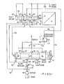
- the device of Figs. 1 and 2 comprises a main valve 20 and a pilot valve 19 for controlling the main valve 20.
- the main and pilot valves are arranged in separate valve blocks which are bolted together with the respective fluid ports in communication witn one another to provide the desired fluid connections as described hereinafter.
- the main valve 20 has a main spool 21 provided with lands 22, 23 and 24 of which the lands 23 and 24 control connection between an inlet port 28 and an outlet port 26, the ports 25 and 27 being in permanent interconnection as hereinafter described and the port 29 which is connected to the port 27 remaining closed off by the land 24.
- a supply passage 31 from a pressure input P is connected to the central port 28 and a return passage 32 leads from the port 26 to a port B used in the present configuration as a tank port.
- a supply of pressure fluid is connected both to the port P and to the port T, which is connected by a passage 30 to the port 2'/.
- the port 25 is connected by a passage 33 to a flow sensor 74 which leads via a passage 71 to a port A, the port A being connected to the hydraulic load in the form of a motor 18 whose outlet is itself connected to tank.
- the spool 21 is biassed away from a null position in which the port 28 is connected to the port 26 to the .left in the drawings by a spring 35 which is disposed in a right-hand control chamber 37. There is no spring in the left-hand control chamber 36 at the other end of the spool 21.
- the main spool 21 is displaced away from its left-hand position towards its null position by the application of a pressure difference between the chambers 36 and 37 by means of the pilot valve 19.
- the pilot valve 19 has a pilot spool 40 which is provided with three lands, 41, 42 and 43 controlling fluid connection between a central inlet port 44 and drain ports 45 and 46 on the one hand and control ports 47 and 48 on the other hand.
- the inlet port 44 is connected by a line 49 to the outlet of a pressure reducing valve 50 which serves to maintain a constant pressure in the line 49.
- the inlet to the pressure reducing valve 50 is connectea to a supply line 51 which can, if desired, be connected to the same source as the port P.
- the pilot spool 40 can be displaced from its neutral position by means of a uni-directional linear force motor 52 which is adapted to produce a force directly proportional to the electrical current applied thereto.
- the force motor 52 incorporates a return spring 70 which biasses the pilot spool 44 to the left and the force produced by the force motor acts to the right.
- the control ports 47 and 48 are connected by respective control lines 53 and 54 to the control chambers 36 and 37 of the main valve 20.
- the pilot valve 19 has annular feedback chambers 55 and 56 at the sides of the lands 41 and 43 facing the respective ends of the pilot spool 40.
- the chambers 57 and 58 at the extreme ends of the spool 40 are connected to a drain line 59 as are the drain ports 45 and 46.
- Feedback pressures are applied from the upstream side of the flow sensor 74 via line 75 to the feedback chamber 56 and from the downstream side of the flow sensor via line 76 to the feedback chamber 55.
- the flow sensor 74 is disposed between the passages 33 and 71 between the port 25 and the port A.
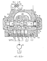
- the flow sensor comprises a housing 328 (Fig. 2) which is connected by fluid connections at its opposite ends to the passages 33 and 71.
- a movable member 326 in the housing divides the housing into two chambers connecting respectively with the ports 25 and A.
- Co-operating surfaces in the housing and on the movable member define a fluid path interconnecting said chambers.
- the flow cross-section of the fluid path is variable dependently upon the position of the movable member which is itself biassed by a spring (shown as two springs 330) to a position in which the fluid path is substantially obturated.
- Said co-operating surfaces are so designed that the pressure drop between the two chambers of the flow sensor is proportional to the rate of fluid flow through the flow sensor.
- the two chambers of the flow sensor are also connected to the feedback lines 75 and 76.
- the flow sensor is preferably constructed in the same manner as the flow sensor described in British Patent No. 1335042. However, as the fluid always flows through the flow sensor in one direction only it is sufficient for the flow sensor to be displaceable in one direction only from its obturating position in which it substantially closes the fluid path.
- the movable member may co-operate with a valve seat when in its obturating position and a bleed path may be provided between the two chambers of the flow sensor to make the flow sensor more sensitive to low flow rates as described in our British Patent Application No. A 2022847.
- the main stage is shown in more detail in Fig. 2 and is in fact identical to the main stage of the device illustrated in British Patent No. 1406326, except that the spool 21 has been modified in that the lands 22 and 23 have been shortened, a return spring 35 is provided in the right-hand control chamber 37 only and a stop 34 is fitted to prevent the spool 21 being displaced to the right beyond its null position. So that the spring 35 can act on the spool 31 when the latter is in its left-hand position, the spring 35 acts via an abutment ring 16 and a tube 17 on the right-hand end of the land 24.
- the lands 22 and 23 have been shortened axially so that the port 27 remains in permanent connection with the port 25 throughout the permitted travel of the main spool 21.
- the port 27 is in permanent connection with the port T through the passage 30 in the housing and the port 25 is in permanent connection with the flow sensor through the passage 33.
- This enables the port T of the existing valve structure to be used as the inlet port to the flow sensor 74 whose outlet port is in permanent connection with the port A to which the motor 18 is connected.
- the port 29 is in permanent connection with the port 27 via a passage 30a provided in the valve block, the port 29 remains closed by the land 24 because the stop 34 prevents the main spool 21 from being displaced to the right beyond its null position.
- the flow sensor 74 is shown in Fig. 2 diagrammatically as being in a block separate from the main valve block it could be incorporated within the main valve block as indicated diagrammatically in the drawings of British Patent No. 1406326.
- the ports T, A, P and B are formed in a port plate 111 attached to the main valve block and also containing a port Y to which the pilot drain line 59 is connected.
- the force motor 52 has been energised to displace the pilot spool 40 to the right as illustrated.
- This connects the control chamber 36 of the main valve 20 to the pilot supply and connects the control chamber 37 to drain.
- the main spool is thereby also displaced to the right as illustrated, away from its extreme left-hand position to .which it is biassed by the spring 35.
- the port 28 In its extreme left-hand position the port 28 is connected directly to tank via the bleed-off path provided by the passages 31 and 32 so that the pump operates at a very low pressure, insufficient to operate the motor even though the supply is permanently connected to the motor via the ports 27 and 25 and the flow sensor 74.
- the movement of the main spool 21 to the right restricts the flow between the ports 28 and 26 thereby throttling the fluid flowing through the bleed-off path so that the pump can develop pressure and supply fluid to the motor 18.
- the resulting fluid flow through the flow sensor 74 produces a pressure difference between the lines 75 and 76 and thereby between the feedback chambers 56 and 55.
- the pressure difference between the chambers 56 and 55 produces a net second force acting on the pilot spool 40 to the left, i.e. in a direction to oppose the electrically dependent first force produced by the force motor 52, thereby tending to return the pilot spool to its null position.
- the pilot spool In the steady state the pilot spool is returned to its null position with the main spool 21 suitably displaced to produce a bleed-off flow and thereby a load speed at which the pressure drop across the flow sensor 74 balances the force applied by the force motor 52.
- the speed of the motor 18 is therefore in the steady state solely dependent upon the electrical signal supplied to the force motor 52.
- the force motor 52 would likely become inoperative and the hydraulic feedback from the flow sensor 74 would shift the pilot spool 40 to its left-hand position in which pressure is applied to the control chamber 37 of the main valve 20 and the control chamber 36 is connected to drain.
- the main valve is thereby immediately fully operated to by-pass the motor 18.
- This fail-safe feature is further enhanced by the single return spring 35 which also biasses the main spool 21, to its left-h ⁇ nd position in which the motor 18 is bypassed.
- the bias spring 70 returns the pilot spool 40 to its left-hand end position in the absence of an electrical signal to the force motor 52 and this applies pilot pressure to the right-hand control chamber 37 to urge the main spool to its fully open left-hand end position.
- Fig. 3 of the drawings illustrates a hydraulic system in.which the present invention is useful.
- the control device is indicated at 100, the main spool 21, the force motor 52 and the flow sensor 74 being represented diagrammatically.
- This drawing clearly shows how the ports T and P are both connected to a main supply line 101, the port A is connected to a hydraulic motor 18 and the port B is connected to tank.
- the main supply line 101 is fed by four fixed displacement pumps 102, 103, .104 and 105, all differing in capacity.
- the capacities of the pumps increase progressively on a binary scale in that the pump 103 has twice the capacity of the pump 102, the pump 104 has twice the capacity of 105 and the pump 105 has twice the capacity of the pump 104.
- each pump delivers to the main supply line 101 through a respective non-return valve 106 and is provided with a respective electrically controlled by-pass valve 107.
- the solenoid 108 of a by-pass valve 107 is not energised, the outlet of the respective pump is connected directly to drain.
- the by-pass valve 107 is closed so that the respective pump can deliver through the respective non-return valve 106.
- An electrical input signal in the form of a flow demand voltage is obtained at an adjustable tapping 110 of a potentiometer 113.
- the electrical signal is supplied on the one hand via a drive amplifier 118 to the force motor 52 and on the other hand to a four-bit analog-to-digital converter 112.
- the converter 112 has four outputs connected via respective drive amplifiers 117 to the solenoids 108 of the by-pass valves 107.
- the converter 112 is programmed to ensure that the appropriate ones of the pumps 102 to 105 are placed in service to meet the flow demand of the hydraulic motor 18 as set by the tapping 110.
- An extra unit signal is applied to the converter 112 by means of a saturation amplifier 115. This achieves a full unit output as soon as the potentiometer 113 leaves the zero position. This ensures that the pumping capacity will exceed the demanded flow output by one unit to allow for 0 to 1 unit of variable bleed-off flow.
- a safety relief valve 116 is connected to the main supply line 101.
- a correction factor may be applied by a pressure transducer 119 to a converter compensation circuit 114 to set the converter 112 to a higher unit of capacity when predicted pump leakage would demand an increased pump capacity in service.
- Fig. 4 shows a modification to the control device of the present invention to enable it to be used in a pressure control mode as well as the flow control mode descirbed above.
- the hydraulic load comprises a ram 130 for axially actuating the feed screw 131 of an injection moulding machine. Whilst the screw is being advanced, its linear velocity is controlled by the control device 100 to a predetermined value, as set on the potentiometer tapping 110. Once the stroke has been substantially completed, the ram 130 is operated to apply a predetermined "packing pressure" to the plastics material in the injection moulding nozzle 136. Hitherto, a separate control valve has been provided to control the ram 130 during the packing phase.
- a feedback pressure P n is obtained from a pressure transducer 132 and is converted into an electrical feedback signal V n which is compared in a comparator 133 with a voltage V D tapped from a potentiometer 137 and representing a desired packing pressure.
- the resulting error signal V E is passed via a pre-amplifier 134 to a changeover switch 135 by means of which the drive amplifier 118 is disconnected from the flow demand potentiometer 113 and instead connected to the output of the pre-amplifier 134, thus closing the pressure control loop.
- the pressure transducer 132 could be connected to the port A in order to measure the hydraulic pressure applied to the ram 130, a more accurate measurement of the actual parameter to be controlled is obtained by placing the pressure transducer 132 in the injection nozzle 136, as shown, so that the pressure P n represents the nozzle pressure.
- the changeover switch 135 is in its illustrated position in which the velocity of the ram 130 is controlled according to the setting of the potentiometer 113, as described above with reference to Figs. 1 and 2 and the pressure feedback loop is broken.
- the switch 135 is changed over so that the pressure in the injection nozzle is adjusted to a value predetermined by the setting of the potentiometer 137 and found by experiment or trial and error to give the optimum quality moulded product.
- a separate hydraulic motor (not shown) is provided for rotating the screw 131 but the screw is not rotated during the injection and packing phases.
- a changeover valve (not shown) in the line 138 between the control device 100 and the ram 130 is actuated to connect the ram to drain and the motor is operated to rotate the screw 131. Rotation of the screw retracts the ram 130 ready for the next injection moulding operating which can be commenced as soon as the screw has stopped turning.
- Fig. 5 illustrates the same injection moulding machine as Fig. 4 but rather more diagrammatically. Like parts are denoted by like reference numerals but a recorder, 140 is connected to the output of the pressure transducer 132 in order to record the nozzle pressure P n against time over an injection cycle and in particular during the injection phase. After the potentiometers 113 and 137 have been adjusted by experiment to obtain the maximum quality injection-moulded product, the recorded pressure/ time or pressure/stroke characteristic relating to that product is used to programme a controller 141 illustrated in Fig. 6.
- Fig. 6 corresponds to Fig. 5 but the potentiometers 113 and 137 have been taken out of circuit and the programmed controller 141 and a buffer amplifier 134a have been placed in circuit.
- the controller 141 is connected to the comparator 133 to feed thereto the signal V D corresponding to the desired nozzle pressure P D at any given time during the injection stroke, the desired nozzle pressure P D being in accordance with the experimentally determined programme.
- the buffer amplifier 134a can be brought into operation during the injection phase instead of the pre-amplifier 134 (which is only used during the packing phase) by means of a changeover switch '142.
- the gain K 1 of the buffer amplifier 134a is generally different from the gain K 2 of the pre-amplifier 134 but the buffer amplifier has an integrating behaviour S.
- the integrating behaviour S is needed to ensure that a signal is provided to keep the pilot valve of the control device 100 open and so keep the ram moving, even when there is no error signal V E .
- the controller 141 brings tne higher gain pre-amplifier 134 into use in place of the buffer amplifier 134a so that the nozzle pressure P n is controlled during the packing phase as described previously.
- the controller 141 can be used during the injection phase only and the potentiometer 137 can be switched into circuit during the packing phase.
- the potentiometer 137 can be incorporated in the controller 141.
- the recorder 140 will record the nozzle pressure against ram travel during the injection phase and the nozzle pressure against time during the packing phase, the ram travel being small or even imperceptible during the packing phase.
Applications Claiming Priority (2)
| Application Number | Priority Date | Filing Date | Title |
|---|---|---|---|
| GB7920932 | 1979-06-15 | ||
| GB7920932A GB2050646B (en) | 1979-06-15 | 1979-06-15 | Hydraulic actuator controls |
Publications (3)
| Publication Number | Publication Date |
|---|---|
| EP0021742A2 true EP0021742A2 (fr) | 1981-01-07 |
| EP0021742A3 EP0021742A3 (en) | 1981-05-27 |
| EP0021742B1 EP0021742B1 (fr) | 1984-05-16 |
Family
ID=10505877
Family Applications (1)
| Application Number | Title | Priority Date | Filing Date |
|---|---|---|---|
| EP80301990A Expired EP0021742B1 (fr) | 1979-06-15 | 1980-06-13 | Dispositif de commande de vérins hydrauliques |
Country Status (4)
| Country | Link |
|---|---|
| US (1) | US4362084A (fr) |
| EP (1) | EP0021742B1 (fr) |
| DE (1) | DE3067821D1 (fr) |
| GB (1) | GB2050646B (fr) |
Cited By (4)
| Publication number | Priority date | Publication date | Assignee | Title |
|---|---|---|---|---|
| EP0251603A2 (fr) * | 1986-06-24 | 1988-01-07 | Group Lotus Plc | Actionneur hydraulique commandé par servo-soupape |
| EP0365341A2 (fr) * | 1988-10-20 | 1990-04-25 | Dosco Overseas Engineering Limited | Contrôle de vitesse automatique |
| DE3901350A1 (de) * | 1989-01-18 | 1990-07-19 | Rexroth Mannesmann Gmbh | Druckwaage fuer ein wegeventil |
| DE3920323A1 (de) * | 1989-06-21 | 1991-01-10 | Rexroth Mannesmann Gmbh | Ventilanordnung zur drehzahlregelung mehrerer hydraulischer antriebsmotore |
Families Citing this family (11)
| Publication number | Priority date | Publication date | Assignee | Title |
|---|---|---|---|---|
| ZA825477B (en) * | 1981-08-21 | 1983-06-29 | Sperry Corp | Hydraulic control system |
| US4622803A (en) * | 1984-06-28 | 1986-11-18 | J. I. Case Company | Header flotation |
| US5042832A (en) * | 1988-01-29 | 1991-08-27 | Nissan Motor Company, Limited | Proportioning valve assembly and actively controlled suspension system utilizing the same |
| US5056561A (en) * | 1990-02-08 | 1991-10-15 | Byers James O | Remote controlled, individually pressure compensated valve |
| US5771181A (en) * | 1994-12-14 | 1998-06-23 | Moore; Robert S. | Generation for virtual reality simulator systems |
| US6286412B1 (en) * | 1999-11-22 | 2001-09-11 | Caterpillar Inc. | Method and system for electrohydraulic valve control |
| DE10020187A1 (de) * | 2000-04-25 | 2001-10-31 | Getrag Getriebe Zahnrad | Hydraulische Schaltung für ein automatisiertes Doppelkupplungsgetriebe für Kraftfahrzeuge |
| DE20116921U1 (de) | 2001-10-15 | 2002-01-03 | Heilmeier & Weinlein | Elektrohydraulisches Motorpumpenaggregat, Anbauelement und Druckbegrenzungsventil |
| US20080078586A1 (en) * | 2006-08-31 | 2008-04-03 | Tettleton Tab S | Mud systems with pressure relief valve |
| DE102009015384B3 (de) * | 2009-03-27 | 2010-09-16 | Hydac Filtertechnik Gmbh | Hydraulische Ventilvorrichtung |
| DE102013206254A1 (de) * | 2013-04-10 | 2014-10-16 | Zf Friedrichshafen Ag | Ventilsystem zur Ansteuerung eines Systemdruckregelsystems |
Citations (9)
| Publication number | Priority date | Publication date | Assignee | Title |
|---|---|---|---|---|
| FR2147119A2 (fr) * | 1971-07-23 | 1973-03-09 | Sperry Rand Corp | |
| FR2158182A1 (fr) * | 1971-11-01 | 1973-06-15 | Gen Electric | |
| GB1335041A (en) * | 1970-01-05 | 1973-10-24 | Sperry Rand Ltd | Hydraulic actuator controls |
| GB1335042A (en) * | 1970-01-05 | 1973-10-24 | Sperry Rand Ltd | Hydraulic actuator controls |
| FR2205632A1 (fr) * | 1972-11-08 | 1974-05-31 | Sperry Rand Ltd | |
| FR2231871A1 (fr) * | 1973-05-29 | 1974-12-27 | Seram | |
| FR2247632A1 (fr) * | 1973-10-10 | 1975-05-09 | Sperry Rand Ltd | |
| FR2322721A1 (fr) * | 1975-09-03 | 1977-04-01 | Bosch Gmbh Robert | Machine a mouler par injection, avec phase de solidification controlee |
| GB1486883A (en) * | 1975-02-18 | 1977-09-28 | Saab Scania Ab | Manufacture control processes and apparatus therefor |
Family Cites Families (4)
| Publication number | Priority date | Publication date | Assignee | Title |
|---|---|---|---|---|
| CA943040A (en) * | 1970-10-06 | 1974-03-05 | Ronald B. Walters | Hydraulic actuator controls |
| DE2146210A1 (de) * | 1971-09-15 | 1973-04-26 | Krauss Maffei Ag | Anordnung zur erzielung abgestufter werte eines gepumpten substanzmengenstromes |
| BE789975A (fr) * | 1971-10-12 | 1973-02-01 | Sanders Associates Inc | Valve de controle de pression et de debit |
| SE371259B (fr) * | 1972-10-05 | 1974-11-11 | Tico Ab |
-
1979
- 1979-06-15 GB GB7920932A patent/GB2050646B/en not_active Expired
-
1980
- 1980-06-13 DE DE8080301990T patent/DE3067821D1/de not_active Expired
- 1980-06-13 US US06/159,362 patent/US4362084A/en not_active Expired - Lifetime
- 1980-06-13 EP EP80301990A patent/EP0021742B1/fr not_active Expired
Patent Citations (15)
| Publication number | Priority date | Publication date | Assignee | Title |
|---|---|---|---|---|
| GB1335041A (en) * | 1970-01-05 | 1973-10-24 | Sperry Rand Ltd | Hydraulic actuator controls |
| GB1335042A (en) * | 1970-01-05 | 1973-10-24 | Sperry Rand Ltd | Hydraulic actuator controls |
| GB1361680A (en) * | 1971-07-23 | 1974-07-30 | Sperry Rand Ltd | Hydraulic actuator controls |
| FR2147119A2 (fr) * | 1971-07-23 | 1973-03-09 | Sperry Rand Corp | |
| GB1372631A (en) * | 1971-11-01 | 1974-11-06 | Gen Electric | Shot volume control for injection moulding machine |
| FR2158182A1 (fr) * | 1971-11-01 | 1973-06-15 | Gen Electric | |
| FR2205632A1 (fr) * | 1972-11-08 | 1974-05-31 | Sperry Rand Ltd | |
| GB1406326A (en) * | 1972-11-08 | 1975-09-17 | Sperry Rand Ltd | Hydraulic actuator controls disazo pigment |
| FR2231871A1 (fr) * | 1973-05-29 | 1974-12-27 | Seram | |
| GB1467328A (en) * | 1973-05-29 | 1977-03-16 | Seram | Pressure fluid sequential control arrangement |
| FR2247632A1 (fr) * | 1973-10-10 | 1975-05-09 | Sperry Rand Ltd | |
| GB1462879A (en) * | 1973-10-10 | 1977-01-26 | Sperry Rand Ltd | Hydraulic actuator controls |
| GB1486883A (en) * | 1975-02-18 | 1977-09-28 | Saab Scania Ab | Manufacture control processes and apparatus therefor |
| FR2322721A1 (fr) * | 1975-09-03 | 1977-04-01 | Bosch Gmbh Robert | Machine a mouler par injection, avec phase de solidification controlee |
| GB1509844A (en) * | 1975-09-03 | 1978-05-04 | Bosch Gmbh Robert | Injection moulding machine and method |
Non-Patent Citations (1)
| Title |
|---|
| Leaflet of Beringer-Hydraulik GmbH Switzerland, Wege-Strom-Proportionalregel-System Typ 3 SRV, issue 4.77 * |
Cited By (6)
| Publication number | Priority date | Publication date | Assignee | Title |
|---|---|---|---|---|
| EP0251603A2 (fr) * | 1986-06-24 | 1988-01-07 | Group Lotus Plc | Actionneur hydraulique commandé par servo-soupape |
| EP0251603A3 (fr) * | 1986-06-24 | 1989-12-06 | Group Lotus Plc | Actionneur hydraulique commandé par servo-soupape |
| EP0365341A2 (fr) * | 1988-10-20 | 1990-04-25 | Dosco Overseas Engineering Limited | Contrôle de vitesse automatique |
| EP0365341A3 (fr) * | 1988-10-20 | 1990-06-13 | Dosco Overseas Engineering Limited | Contrôle de vitesse automatique |
| DE3901350A1 (de) * | 1989-01-18 | 1990-07-19 | Rexroth Mannesmann Gmbh | Druckwaage fuer ein wegeventil |
| DE3920323A1 (de) * | 1989-06-21 | 1991-01-10 | Rexroth Mannesmann Gmbh | Ventilanordnung zur drehzahlregelung mehrerer hydraulischer antriebsmotore |
Also Published As
| Publication number | Publication date |
|---|---|
| EP0021742B1 (fr) | 1984-05-16 |
| US4362084A (en) | 1982-12-07 |
| EP0021742A3 (en) | 1981-05-27 |
| DE3067821D1 (en) | 1984-06-20 |
| GB2050646B (en) | 1983-04-13 |
| GB2050646A (en) | 1981-01-07 |
Similar Documents
| Publication | Publication Date | Title |
|---|---|---|
| US4362084A (en) | Hydraulic actuator controls | |
| US3987622A (en) | Load controlled fluid system having parallel work elements | |
| US3954046A (en) | Valve arrangement for controlling a reversible hydraulically operated device | |
| US3455210A (en) | Adjustable,metered,directional flow control arrangement | |
| DE69602923T3 (de) | Elektrohydraulische proportionale steuerventilvorrichtung | |
| JP4653091B2 (ja) | 少なくとも2つの流体圧コンシューマに圧力手段を供給するための制御装置および方法 | |
| US4699571A (en) | Control valve for a variable displacement pump | |
| JP2678607B2 (ja) | 少なくとも2つのアクチュエータの流体圧駆動用制御装置 | |
| KR101085984B1 (ko) | 2개 이상의 유압 액추에이터를 제어하기 위한 방법 및 장치 | |
| JPH0448967B2 (fr) | ||
| US4732076A (en) | Apparatus for the control of a hydromotor | |
| CN111577680B (zh) | 一种负载敏感分流阀、变速同步驱动系统及工作方法 | |
| US3959969A (en) | Apparatus for regulating the pressure and rate of flow of fluid supplied by a variable-delivery pump | |
| JPS63176802A (ja) | 少なくとも1基のポンプから液圧が供給されている少なくとも2台の液圧消費装置の制御装置 | |
| US3987626A (en) | Controls for multiple variable displacement pumps | |
| US3854382A (en) | Hydraulic actuator controls | |
| US5261232A (en) | Valve system for supplying fluid from a pair of fluid pressure sources to a load | |
| US3191382A (en) | Hydraulic system | |
| US5170692A (en) | Hydraulic control system | |
| US4275643A (en) | Hydraulic control systems | |
| US4967554A (en) | Commonly-piloted directional control valve and load pressure signal line relieving switching valve | |
| Hu et al. | Realization of programmable control using a set of individually controlled electrohydraulic valves | |
| US4429619A (en) | Control system for a hydraulic load | |
| JP2929021B2 (ja) | 可変容積型ポンプ | |
| GB1292162A (en) | Improvements in and relating to the electro-hydraulic remote control of hydraulic multi-position valves |
Legal Events
| Date | Code | Title | Description |
|---|---|---|---|
| PUAI | Public reference made under article 153(3) epc to a published international application that has entered the european phase |
Free format text: ORIGINAL CODE: 0009012 |
|
| AK | Designated contracting states |
Designated state(s): CH DE FR IT SE |
|
| PUAL | Search report despatched |
Free format text: ORIGINAL CODE: 0009013 |
|
| AK | Designated contracting states |
Designated state(s): CH DE FR IT SE |
|
| 17P | Request for examination filed |
Effective date: 19810424 |
|
| ITF | It: translation for a ep patent filed |
Owner name: BARZANO' E ZANARDO ROMA S.P.A. |
|
| GRAA | (expected) grant |
Free format text: ORIGINAL CODE: 0009210 |
|
| AK | Designated contracting states |
Designated state(s): CH DE FR IT LI SE |
|
| PGFP | Annual fee paid to national office [announced via postgrant information from national office to epo] |
Ref country code: DE Payment date: 19840614 Year of fee payment: 5 |
|
| PGFP | Annual fee paid to national office [announced via postgrant information from national office to epo] |
Ref country code: FR Payment date: 19840615 Year of fee payment: 5 Ref country code: CH Payment date: 19840615 Year of fee payment: 5 |
|
| REF | Corresponds to: |
Ref document number: 3067821 Country of ref document: DE Date of ref document: 19840620 |
|
| PGFP | Annual fee paid to national office [announced via postgrant information from national office to epo] |
Ref country code: SE Payment date: 19840630 Year of fee payment: 5 |
|
| ET | Fr: translation filed | ||
| PLBE | No opposition filed within time limit |
Free format text: ORIGINAL CODE: 0009261 |
|
| STAA | Information on the status of an ep patent application or granted ep patent |
Free format text: STATUS: NO OPPOSITION FILED WITHIN TIME LIMIT |
|
| 26N | No opposition filed | ||
| PG25 | Lapsed in a contracting state [announced via postgrant information from national office to epo] |
Ref country code: SE Effective date: 19850614 |
|
| PG25 | Lapsed in a contracting state [announced via postgrant information from national office to epo] |
Ref country code: LI Effective date: 19850630 Ref country code: CH Effective date: 19850630 |
|
| PG25 | Lapsed in a contracting state [announced via postgrant information from national office to epo] |
Ref country code: FR Free format text: LAPSE BECAUSE OF NON-PAYMENT OF DUE FEES Effective date: 19860228 |
|
| REG | Reference to a national code |
Ref country code: CH Ref legal event code: PL |
|
| PG25 | Lapsed in a contracting state [announced via postgrant information from national office to epo] |
Ref country code: DE Effective date: 19860301 |
|
| REG | Reference to a national code |
Ref country code: FR Ref legal event code: ST |
|
| EUG | Se: european patent has lapsed |
Ref document number: 80301990.0 Effective date: 19860728 |