EP0021547B1 - Method of and apparatus for washing and cleaning membrane filtration units - Google Patents
Method of and apparatus for washing and cleaning membrane filtration units Download PDFInfo
- Publication number
- EP0021547B1 EP0021547B1 EP80200614A EP80200614A EP0021547B1 EP 0021547 B1 EP0021547 B1 EP 0021547B1 EP 80200614 A EP80200614 A EP 80200614A EP 80200614 A EP80200614 A EP 80200614A EP 0021547 B1 EP0021547 B1 EP 0021547B1
- Authority
- EP
- European Patent Office
- Prior art keywords
- circuit
- inlet
- washing liquid
- washing
- outlet
- Prior art date
- Legal status (The legal status is an assumption and is not a legal conclusion. Google has not performed a legal analysis and makes no representation as to the accuracy of the status listed.)
- Expired
Links
- 238000005406 washing Methods 0.000 title claims abstract description 101
- 238000005374 membrane filtration Methods 0.000 title claims abstract description 54
- 238000004140 cleaning Methods 0.000 title claims abstract description 22
- 238000000034 method Methods 0.000 title claims abstract description 17
- 239000007788 liquid Substances 0.000 claims abstract description 97
- 238000005086 pumping Methods 0.000 claims description 12
- 230000003247 decreasing effect Effects 0.000 claims description 3
- 239000012528 membrane Substances 0.000 abstract description 15
- 238000009434 installation Methods 0.000 description 7
- 230000000694 effects Effects 0.000 description 5
- 239000012535 impurity Substances 0.000 description 5
- 239000000645 desinfectant Substances 0.000 description 3
- 238000001914 filtration Methods 0.000 description 3
- 102000004190 Enzymes Human genes 0.000 description 2
- 108090000790 Enzymes Proteins 0.000 description 2
- 239000012459 cleaning agent Substances 0.000 description 2
- 238000009825 accumulation Methods 0.000 description 1
- 229920002301 cellulose acetate Polymers 0.000 description 1
- 238000006243 chemical reaction Methods 0.000 description 1
- 230000001419 dependent effect Effects 0.000 description 1
- 229920002521 macromolecule Polymers 0.000 description 1
- 230000002906 microbiologic effect Effects 0.000 description 1
- 239000012466 permeate Substances 0.000 description 1
- 229920003023 plastic Polymers 0.000 description 1
- 239000004033 plastic Substances 0.000 description 1
- 238000000746 purification Methods 0.000 description 1
- 238000001223 reverse osmosis Methods 0.000 description 1
- 239000000126 substance Substances 0.000 description 1
- 238000000108 ultra-filtration Methods 0.000 description 1
Images
Classifications
-
- B—PERFORMING OPERATIONS; TRANSPORTING
- B01—PHYSICAL OR CHEMICAL PROCESSES OR APPARATUS IN GENERAL
- B01D—SEPARATION
- B01D65/00—Accessories or auxiliary operations, in general, for separation processes or apparatus using semi-permeable membranes
- B01D65/02—Membrane cleaning or sterilisation ; Membrane regeneration
-
- B—PERFORMING OPERATIONS; TRANSPORTING
- B01—PHYSICAL OR CHEMICAL PROCESSES OR APPARATUS IN GENERAL
- B01D—SEPARATION
- B01D2313/00—Details relating to membrane modules or apparatus
- B01D2313/24—Specific pressurizing or depressurizing means
- B01D2313/243—Pumps
-
- B—PERFORMING OPERATIONS; TRANSPORTING
- B01—PHYSICAL OR CHEMICAL PROCESSES OR APPARATUS IN GENERAL
- B01D—SEPARATION
- B01D2317/00—Membrane module arrangements within a plant or an apparatus
- B01D2317/02—Elements in series
- B01D2317/022—Reject series
-
- B—PERFORMING OPERATIONS; TRANSPORTING
- B01—PHYSICAL OR CHEMICAL PROCESSES OR APPARATUS IN GENERAL
- B01D—SEPARATION
- B01D2321/00—Details relating to membrane cleaning, regeneration, sterilization or to the prevention of fouling
- B01D2321/02—Forward flushing
Definitions
- the present invention relates to a method of washing and cleaning a plurality of membrane filtration units, aligned in series, each of said units being part of a circuit provided with a circulation pump, introducing washing liquid whether or not containing washing bodies, through membrane filtration units.
- a method of this type for washing and cleaning a plurality of membrane filtration units aligned In series, is known in the art.
- impurities will accumulate upon the membrane surface, which surface contacts liquids to be purified; the presence of said impurities may give rise to a decrease in the efficiency of the membranes.
- a constant washing and cleaning of said membranes in membrane filtration units is required.
- washing and cleaning is effected with a disinfectant in order to prevent microbiological growth in the membrane filtration units, said accumulation being due to high temperatures occurring during said membrane filtrations, due to which the growth of microbes will rapidly multiply, which growth may likewise give rise to a large number of disadvantageous effects.
- washing and cleaning effects may be Improved in tubular membranes by including spherical bodies In the washing liquids, which bodies exert a mechanical cleaning action upon membranes.
- spherical bodies In the washing liquids, which bodies exert a mechanical cleaning action upon membranes.
- membrane units consisting of helically wound membrane modules only washing liquid is used which may contain a disinfectant in a later stage.
- the present invention aims to provide a method of and apparatus for washing and cleaning a plurality of filtration units aligned in series, whereby the aforementioned disadvantages do not occur.
- This object is attained in accordance with the present invention in that a quantity of washing liquid is fed to the circuits which exceeds the pumping capacity of the respective circulation pump
- the circulation pump will pump the washing liquids entirely through the membrane filtration unit without particular close-off valves having to be opened or closed in order to effect the washing liquid to be discharged after it has passed the respective membrane filtration unit.
- the amount of required washing liquid is also less as the change to the washing operation can be effected more rapidly.
- the flow viscosity during washing is high and thus washing can be performed in a short period of time, which involves a lower temperature decrease of the installation and a smaller consumption of cleaning agents.
- the fact that the temperature of the present installation is substantially maintained is very important, as cleaning with enzymes containing washing liquids requires a very limited temperature range for an effective action of said enzymes.
- the washing liquid is preferably fed to the circuit at a point located between the circulation pump inlet and the outlet of the respective unit being connected with the circuit, whilst on the other hand, said washing liquid is discharged from the circuit at a location situated between the washing liquid inlet and the outlet of the respective membrane filtration unit.
- the circulation pump will only pump washing liquid through the membrane filtration unit, whilst said pump will redischarge said washing liquid from the circuit, after said liquid has passed the relative membrane filtration unit, so that the washing liquid cannot possibly be re-introduced into said circulation pump.
- the excess washing liquid will actually cause part of the washing liquid to flow from the inlet towards the washing liquid outlet of the circuit. Due to these membranes, an optimum cleaning of the membrane filtration units is obtained.
- the present invention also comprises an apparatus for washing and cleaning a plurality of membrane filtration units aligned in series, each of said units being accommodated in a circuit comprising a circulation pump, each circuit being provided with a circuit inlet for feeding a . liquid into the respective units and a circuit outlet for the discharge of liquid from the circuit, which circuit outlet is connected with a consecutive circuit inlet or with an apparatus outlet, said apparatus comprising a washing liquid inlet pump having a pumping capacity exceeding that of the pumping capacity of the circulation pump of a circuit into which washing liquid is fed.
- membrane filtration units As far as in the foregoing the expression "membrane filtration units" is used, such expression is to be understood as units which are employed for ultrafiltration and units which are employed for reverse osmosis.
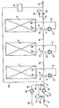
- the drawing shows an apparatus comprising three membrane filtration units 1, 2 and 3 which are aligned in series.
- Each membrane filtration unit comprises a number of pressure supporting pipes known per se, the inner side of said pipes being provided with a non woven tube supporting on its inner side a filtration membrane.
- Said filtration membrane may consist of cellulose acetate, but also of other macromolecular substances. It will be obvious, however, that instead of pressure supporting pipes, a helically wound membrane filtration unit may be accommodated in the membrane filtration units, said helically wound unit then serving for the purification of liquid to be purified.
- the membrane filtration unit 1 is, through membrane filtration unit outlet 35, connected with circuit 6, which circuit 6 debouches into the membrane filtration unit inlet 36.
- the membrane filtration unit 2 is, through membrane filtration unit outlet 35', connected with circuit 7, which in turn is connected with the membrane filtration unit 2 through membrane filtration unit inlet 36'.
- membrane filtration unit 3 is, through outlet 35", connected with circuit 8, which debouches into membrane filtration unit inlet 36".
- Each circuit 6, 7, 8 comprises a circulation pump 12, which pumps liquid through the circuit and the membrane filtration unit connected therewith.
- Circuit 6 connected with the first membrane filtration unit 1, is provided with a circuit inlet 9 and a circuit outlet 13. Said circuit outlet 13 is located between the membrane filtration unit outlet 35, and the circulation pump 12, whereas the circuit inlet 9 is situated between said circuit outlet 13 and said circulation pump 12.
- a continuous line part 16 is accommodated in between the circuit inlet 9 and the circuit outlet 13, thus causing a closed circuit 6 to be obtained.
- the circuit outlet 13 of the first circuit 6 is connected with the circuit outlet 10 of the second circuit 7, through line 33, said second circuit 7 being likewise provided with a second circuit outlet 14.
- the inlet 10 and the outlet 14 of the second circuit 7 are provided in a manner identical to that of the circuit inlet 9 and the circuit outlet 13 in the first circuit 6.
- the outlet 14 and the inlet 10 of the second circuit 7 are interconnected through line part 17.
- the outlet 14 of the second circuit debouches, through line 34, into the inlet 11 of the third circuit 8, which third circuit 8 is likewise provided with an outlet 15 being connected with an outlet line 19, in which a close-off valve 22 is accommodated.
- the outlet line 19 is connected with a line 21 debouching at either side of the close-off valve 22 into line 19.
- Said line 21 further comprises a close-off valve 20.
- the inlet 11 and the outlet 15 of the third circuit 8 are interconnected through line part 18.
- Inlet 9 of the first circuit 6 is connected with a main supply line 5, being connected in turn with a high pressure pump 32, which high pressure pump is in turn connected with a liquid supply line 3' for the supply of liquid to be purified.
- Line 3' incorporates a close-off valve 4.
- the apparatus further comprises a washing liquid inlet 23, adjoining a washing liquid inlet pump 24 in the form of a centrifugal-pump, which centrifugal pump adjoins a line 25 debouching into a branch line 27, which, through line part 28, debouches into supply inlet line 3' in between the said close-off valve 4 and the high pressure pump 32, while, on the other hand, line 25 debouches into supply line 5 through line part 26, incorporating a close-off valve 30.
- a washing liquid inlet 23 adjoining a washing liquid inlet pump 24 in the form of a centrifugal-pump, which centrifugal pump adjoins a line 25 debouching into a branch line 27, which, through line part 28, debouches into supply inlet line 3' in between the said close-off valve 4 and the high pressure pump 32, while, on the other hand, line 25 debouches into supply line 5 through line part 26, incorporating a close-off valve 30.
- Centrifugal pump 24 for washing liquid is actuated when close-off valves 30 and 31 are closed, so that line 25 is filled with washing liquid.
- Said washing liquid subsequently streams through branch line part 27 towards close-off valve 31, which-valve 31 is opened by the relative pressure, whilst simultaneously liquid inlet valve 4 is closed.
- close-off valve 30 is opened, so that washing liquid supplied through line part 28 and line part 26, streams into inlet line 5.
- the quantity of washing liquid fed into circuit inlet 9, is chosen in such a way that the fed quantity of washing liquid exceeds the predetermined pumping capacity of the circulation pump 12.
- washing liquid will move; through connection line part 16, towards circuit outlet 13, while, on the other hand, circulation pump 12 will pump the incoming liquid through inlet 9, through the first membrane filtration unit 1.
- the washing liquid After having passed said membrane filtration unit 1 through outlet 35 the washing liquid will flow away through circuit outlet 13 of the first circuit 6 and will subsequently flow through line 33 into inlet 10 of the second circuit 7.
- inlet 10 is also fed with a quantity of washing liquid, which exceeds the predetermined capacity of the circulation pump 12.
- the circulation pump 12 of the second circuit 7 also pumps the washing liquid through the second membrane filtration unit 2, which washing liquid will escape through membrane filtration unit outlet 35' and circuit outlet 14 of the second circuit 7.
- washing liquid Since inlet 10 is fed with a quantity of washing liquid, which exceeds the pumping capacity of circulation pump 12, washing liquid will also flow towards outlet 14, through line 17. Consequently excess liquids will be expelled by washing liquid in a very convenient manner. Washing liquid discharged through outlet 14 of second circuit 7, flows through line 24, into inlet 11 of third circuit 8 and after having passed third membrane filtration unit 3, subsequently flows. through outlet 15 of third circuit 8. Said removal of washing liquid may easily take place by opening the close-off valves 20 and 22. As the quantity of washing liquid being introduced Into inlet 11 of the third circuit 8, also exceeds the pumping capacity of circulation pump 12, which is accommodated in third circuit 8, washing liquid will flow through connection line 18, towards oqtlet 15 of third circuit 8. The washing liquid escaping through outlet 15, will arrive in line 19.
- the high pressure pump 32 may proceed its action, as in the apparatus according to the Invention, high pressure cannot possibly be exerted due to close-off valves 20 and 22 being opened.
- said high pressure pump may be stopped during a further washing operation.
- the washing liquid is fed by means of, for example, a centrifugal pump exerting a pressure of e.g. 3, whilst said centrifugal pump, being operable during the membrane filtration, is able to exert pressures in the system of e.g. 38 bar.
- a centrifugal pump exerting a pressure of e.g. 3
- said centrifugal pump being operable during the membrane filtration, is able to exert pressures in the system of e.g. 38 bar.
- the latter is, of course, dependent upon opening or closing the close-off valves 20, 22, respectively.
- the close-off valves 30 and 31 are closed and liquid inlet 4 is re-opened whilst close-off valve 22 in outlet line 19 is closed as well. Since less washing liquid may escape through close-off valve 20, than through both close-off valves 20 and 22 together, said washing liquid will be subjected to a high pressure when high pressure pump 32 is operating.
- the fed liquid to be purified is streaming through line 3' and arrives through line 5 into Inlet 9 of the first circuit 6, whereafter said liquid Is circulated by the circulation pump.
- said circulating pumping permeate passes the membranes, whereafter more impure liquid escapes through line 33 towards second circuit 7 and after having passed the second membrane filtration unit 2, still more impure liquid will stream into third circuit 8, through line 34.
- the pumping capacity of the circulation pumps 12 is e.g. 123 m3/h, whilst the capacity of the centrifugal pump 24 is 130 m3/h.
- the high pressure pump 32 has, for instance, a capacity ranging from 23 to 40 m3/h, and is able to increase the pressure of liquid to be purified, from 15 to 38 bar.
- said cleaning bodies may be fed through line 29, and after having passed the entire installation said bodies may be recovered in a cleaning body storage vessel 37 and, starting again from said vessel 37, be reintroduced into line 5.
- a chemical cleaning agent or a disinfectant may be added to the washing liquid.
- an additional washing liquid inlet pump 24 is used for supplying an amount of washing liquid to the circuit which amount is greater than the amount of liquid pumped by circuit pump 12 under normal working conditions.
- valves 20 and 22 in end outlet 19 have to be opened more.
- the washing operation takes place at a low pressure and with a high flow velocity, the washing is very effective, so that fewer washing operations per day are necessary.
Landscapes
- Chemical & Material Sciences (AREA)
- Chemical Kinetics & Catalysis (AREA)
- Separation Using Semi-Permeable Membranes (AREA)
Priority Applications (1)
| Application Number | Priority Date | Filing Date | Title |
|---|---|---|---|
| AT80200614T ATE3185T1 (de) | 1979-07-03 | 1980-06-27 | Verfahren und apparat zum waschen und reinigen von membranfiltrationseinheiten. |
Applications Claiming Priority (2)
| Application Number | Priority Date | Filing Date | Title |
|---|---|---|---|
| NL7905194 | 1979-07-03 | ||
| NLAANVRAGE7905194,A NL172405C (nl) | 1979-07-03 | 1979-07-03 | Werkwijze en inrichting voor het spoelen van een aantal in serie geplaatste filtratie-eenheden voor het uitvoeren van een membraanfiltratie onder druk. |
Publications (3)
| Publication Number | Publication Date |
|---|---|
| EP0021547A2 EP0021547A2 (en) | 1981-01-07 |
| EP0021547A3 EP0021547A3 (en) | 1981-01-14 |
| EP0021547B1 true EP0021547B1 (en) | 1983-05-04 |
Family
ID=19833477
Family Applications (1)
| Application Number | Title | Priority Date | Filing Date |
|---|---|---|---|
| EP80200614A Expired EP0021547B1 (en) | 1979-07-03 | 1980-06-27 | Method of and apparatus for washing and cleaning membrane filtration units |
Country Status (6)
| Country | Link |
|---|---|
| US (1) | US4361485A (enExample) |
| EP (1) | EP0021547B1 (enExample) |
| JP (1) | JPS5631408A (enExample) |
| AT (1) | ATE3185T1 (enExample) |
| DE (1) | DE3062963D1 (enExample) |
| NL (1) | NL172405C (enExample) |
Families Citing this family (20)
| Publication number | Priority date | Publication date | Assignee | Title |
|---|---|---|---|---|
| US4857181A (en) * | 1986-10-30 | 1989-08-15 | Cobe Laboratories, Inc. | Control of cleaning of dialysate preparation apparatus |
| US4784771A (en) * | 1987-08-03 | 1988-11-15 | Environmental Water Technology, Inc. | Method and apparatus for purifying fluids |
| JPH02174919A (ja) * | 1988-12-27 | 1990-07-06 | Miura Co Ltd | 膜モジュール式水処理装置 |
| JPH0657304B2 (ja) * | 1988-12-27 | 1994-08-03 | 三浦工業株式会社 | 膜モジュール式水処理装置 |
| US5143601A (en) * | 1989-10-06 | 1992-09-01 | Water Factory Corporation | Fluid purification system |
| US5434381A (en) * | 1993-09-13 | 1995-07-18 | T-Star Industrial Electronics, Inc. | Apparatus for filtering machining liquid of an electrical discharge machine |
| JPH08108048A (ja) * | 1994-10-12 | 1996-04-30 | Toray Ind Inc | 逆浸透分離装置及び逆浸透分離方法 |
| US5772624A (en) * | 1995-07-20 | 1998-06-30 | Medisystems Technology Corporation | Reusable blood lines |
| EP1329425A1 (en) * | 2002-01-18 | 2003-07-23 | Toray Industries, Inc. | Desalination method and desalination apparatus |
| US7368139B1 (en) * | 2002-03-15 | 2008-05-06 | Bronnert Herve X | Aseptic processing system for fruit filling |
| US7632410B2 (en) * | 2003-08-21 | 2009-12-15 | Christopher Heiss | Universal water purification system |
| US7291267B2 (en) * | 2004-01-30 | 2007-11-06 | Ljc Technologies, L.L.C. | Molecular separator |
| KR100595408B1 (ko) * | 2005-12-14 | 2006-07-04 | 김인석 | 터널 등기구 |
| US8119008B2 (en) * | 2006-07-10 | 2012-02-21 | Christopher Heiss | Fluid purification methods and devices |
| WO2009009465A1 (en) * | 2007-07-06 | 2009-01-15 | Christopher William Heiss | Electrocoagulation reactor and water treatment system and method |
| US20110049048A1 (en) * | 2009-09-03 | 2011-03-03 | General Electric Company | Water purification system |
| WO2012129501A2 (en) | 2011-03-23 | 2012-09-27 | Nxstage Medical, Inc. | Peritoneal dialysis systems, devices, and methods |
| US20130146541A1 (en) | 2011-12-13 | 2013-06-13 | Nxstage Medical, Inc. | Fluid purification methods, devices, and systems |
| WO2018237375A1 (en) | 2017-06-24 | 2018-12-27 | Nxstage Medical, Inc. | Peritoneal dialysis fluid preparation and/or treatment devices methods and systems |
| US11364328B2 (en) | 2018-02-28 | 2022-06-21 | Nxstage Medical, Inc. | Fluid preparation and treatment devices methods and systems |
Family Cites Families (10)
| Publication number | Priority date | Publication date | Assignee | Title |
|---|---|---|---|---|
| US3493495A (en) * | 1968-01-17 | 1970-02-03 | Morris Mendelson | Apparatus and process for the osmotic separation of water from a saline solution |
| GB1250482A (enExample) * | 1968-03-19 | 1971-10-20 | ||
| US3498910A (en) * | 1968-09-03 | 1970-03-03 | Morris Mendelson | Apparatus and process for the controlled osmotic separation of water from sea water |
| JPS4831774A (enExample) * | 1971-08-26 | 1973-04-26 | ||
| US3846295A (en) * | 1972-04-06 | 1974-11-05 | Ultrascience Inc | Method and apparatus for use in water purification by reverse osmosis |
| US3756408A (en) * | 1972-06-15 | 1973-09-04 | Osmonics Inc | Separation system |
| JPS50109179A (enExample) * | 1974-02-06 | 1975-08-28 | ||
| NL177465C (nl) * | 1974-03-28 | 1985-10-01 | Wafilin Bv | Installatie voor membraanfiltratie. |
| NL7404265A (en) * | 1974-03-28 | 1975-09-30 | Wafilin Bv | Membrane filtration in series of units - where the feed is switched periodically to the last unit to cool and clean it |
| US4200533A (en) * | 1978-06-28 | 1980-04-29 | Brandon Craig A | Hyperfiltration apparatus and method of fluid treatment |
-
1979
- 1979-07-03 NL NLAANVRAGE7905194,A patent/NL172405C/xx not_active IP Right Cessation
-
1980
- 1980-06-27 EP EP80200614A patent/EP0021547B1/en not_active Expired
- 1980-06-27 DE DE8080200614T patent/DE3062963D1/de not_active Expired
- 1980-06-27 AT AT80200614T patent/ATE3185T1/de active
- 1980-07-01 US US06/165,042 patent/US4361485A/en not_active Expired - Lifetime
- 1980-07-03 JP JP9160780A patent/JPS5631408A/ja active Granted
Also Published As
| Publication number | Publication date |
|---|---|
| NL172405C (nl) | 1983-09-01 |
| US4361485A (en) | 1982-11-30 |
| EP0021547A2 (en) | 1981-01-07 |
| NL7905194A (nl) | 1980-11-28 |
| NL172405B (nl) | 1983-04-05 |
| EP0021547A3 (en) | 1981-01-14 |
| JPH0255098B2 (enExample) | 1990-11-26 |
| DE3062963D1 (en) | 1983-06-09 |
| ATE3185T1 (de) | 1983-05-15 |
| JPS5631408A (en) | 1981-03-30 |
Similar Documents
| Publication | Publication Date | Title |
|---|---|---|
| EP0021547B1 (en) | Method of and apparatus for washing and cleaning membrane filtration units | |
| JPH06277664A (ja) | 表流水の膜浄化方法およびそのための装置 | |
| EP2633898A1 (en) | Hollow fiber membrane filtration device and method for washing hollow fiber membrane module | |
| RU2440180C2 (ru) | Способ переработки моющих жидкостей и устройство для этой цели | |
| CN212640033U (zh) | 用于乳品厂的清洗液再生的膜系统 | |
| AU2004298748B2 (en) | Membrane filter system comprising parallel cross-flow filter modules | |
| HU217640B (hu) | Eljárás és berendezés szilárd/folyékony keverékek, főként rostos gyümölcslevek besűrítésére membrántechnológiával | |
| EP0669159A1 (en) | Back wash method for filtration modules using internally pressurized hollow fibers | |
| JP2017209654A (ja) | 逆浸透膜装置及び逆浸透膜装置の運転方法 | |
| JP4882164B2 (ja) | 膜濾過装置 | |
| US20110056894A1 (en) | Method and system for filtering water, in particular, an ultrafiltration method | |
| US3812969A (en) | Apparatus for fluid treatment | |
| JP4439526B2 (ja) | 製品を完全濾過する方法とこの方法を実施する装置 | |
| JPS5811090A (ja) | 純水製造用逆浸透装置又は限外「ろ」過装置 | |
| RU2092235C1 (ru) | Способ промывки фильтрационных модулей установки для осветления жидкостей | |
| JP6143159B2 (ja) | 逆洗型ろ過装置およびろ過エレメントの付着物除去方法 | |
| JP5141855B2 (ja) | 膜分離装置 | |
| RU2323036C2 (ru) | Способ концентрирования водных растворов биологически активных веществ и установка для его реализации | |
| JPH1157415A (ja) | 膜脱気装置の運転方法及び膜脱気装置 | |
| CN201959726U (zh) | 电渗析的循环串联动态备用运行系统装置 | |
| CN219518405U (zh) | 一种物料浓缩系统 | |
| JP4560701B2 (ja) | 濾過膜モジュールの洗浄方法 | |
| KR0153586B1 (ko) | 정수기의 필터자동 세척 시스템 | |
| JP5136739B2 (ja) | 膜分離装置及びその洗浄方法 | |
| CN218435984U (zh) | 一种电泳涂装超滤管阀系统及电泳超滤装置 |
Legal Events
| Date | Code | Title | Description |
|---|---|---|---|
| PUAI | Public reference made under article 153(3) epc to a published international application that has entered the european phase |
Free format text: ORIGINAL CODE: 0009012 |
|
| PUAL | Search report despatched |
Free format text: ORIGINAL CODE: 0009013 |
|
| AK | Designated contracting states |
Designated state(s): AT BE CH DE FR GB IT LU NL SE |
|
| AK | Designated contracting states |
Designated state(s): AT BE CH DE FR GB IT LU NL SE |
|
| 17P | Request for examination filed |
Effective date: 19801118 |
|
| ITF | It: translation for a ep patent filed | ||
| GRAA | (expected) grant |
Free format text: ORIGINAL CODE: 0009210 |
|
| AK | Designated contracting states |
Designated state(s): AT BE CH DE FR GB IT LI LU NL SE |
|
| REF | Corresponds to: |
Ref document number: 3185 Country of ref document: AT Date of ref document: 19830515 Kind code of ref document: T |
|
| REF | Corresponds to: |
Ref document number: 3062963 Country of ref document: DE Date of ref document: 19830609 |
|
| PGFP | Annual fee paid to national office [announced via postgrant information from national office to epo] |
Ref country code: LU Payment date: 19830621 Year of fee payment: 4 |
|
| PG25 | Lapsed in a contracting state [announced via postgrant information from national office to epo] |
Ref country code: LU Free format text: LAPSE BECAUSE OF NON-PAYMENT OF DUE FEES Effective date: 19830630 |
|
| ET | Fr: translation filed | ||
| PLBE | No opposition filed within time limit |
Free format text: ORIGINAL CODE: 0009261 |
|
| STAA | Information on the status of an ep patent application or granted ep patent |
Free format text: STATUS: NO OPPOSITION FILED WITHIN TIME LIMIT |
|
| 26N | No opposition filed | ||
| GBPR | Gb: patent revoked under art. 102 of the ep convention designating the uk as contracting state | ||
| PGFP | Annual fee paid to national office [announced via postgrant information from national office to epo] |
Ref country code: CH Payment date: 19910528 Year of fee payment: 12 |
|
| PGFP | Annual fee paid to national office [announced via postgrant information from national office to epo] |
Ref country code: AT Payment date: 19910627 Year of fee payment: 12 |
|
| ITTA | It: last paid annual fee | ||
| PG25 | Lapsed in a contracting state [announced via postgrant information from national office to epo] |
Ref country code: AT Effective date: 19920627 |
|
| PG25 | Lapsed in a contracting state [announced via postgrant information from national office to epo] |
Ref country code: LI Effective date: 19920630 Ref country code: CH Effective date: 19920630 |
|
| REG | Reference to a national code |
Ref country code: GB Ref legal event code: 732 |
|
| REG | Reference to a national code |
Ref country code: CH Ref legal event code: PL |
|
| EAL | Se: european patent in force in sweden |
Ref document number: 80200614.8 |
|
| PGFP | Annual fee paid to national office [announced via postgrant information from national office to epo] |
Ref country code: SE Payment date: 19950515 Year of fee payment: 16 |
|
| PGFP | Annual fee paid to national office [announced via postgrant information from national office to epo] |
Ref country code: GB Payment date: 19950516 Year of fee payment: 16 |
|
| PGFP | Annual fee paid to national office [announced via postgrant information from national office to epo] |
Ref country code: DE Payment date: 19950519 Year of fee payment: 16 |
|
| PGFP | Annual fee paid to national office [announced via postgrant information from national office to epo] |
Ref country code: BE Payment date: 19950607 Year of fee payment: 16 |
|
| PGFP | Annual fee paid to national office [announced via postgrant information from national office to epo] |
Ref country code: FR Payment date: 19950628 Year of fee payment: 16 |
|
| PGFP | Annual fee paid to national office [announced via postgrant information from national office to epo] |
Ref country code: NL Payment date: 19950629 Year of fee payment: 16 |
|
| PG25 | Lapsed in a contracting state [announced via postgrant information from national office to epo] |
Ref country code: GB Effective date: 19960627 |
|
| PG25 | Lapsed in a contracting state [announced via postgrant information from national office to epo] |
Ref country code: SE Effective date: 19960628 |
|
| PG25 | Lapsed in a contracting state [announced via postgrant information from national office to epo] |
Ref country code: BE Effective date: 19960630 |
|
| BERE | Be: lapsed |
Owner name: WAFILIN B.V. Effective date: 19960630 |
|
| PG25 | Lapsed in a contracting state [announced via postgrant information from national office to epo] |
Ref country code: NL Effective date: 19970101 |
|
| GBPC | Gb: european patent ceased through non-payment of renewal fee |
Effective date: 19960627 |
|
| PG25 | Lapsed in a contracting state [announced via postgrant information from national office to epo] |
Ref country code: FR Effective date: 19970228 |
|
| PG25 | Lapsed in a contracting state [announced via postgrant information from national office to epo] |
Ref country code: DE Effective date: 19970301 |
|
| EUG | Se: european patent has lapsed |
Ref document number: 80200614.8 |
|
| NLV4 | Nl: lapsed or anulled due to non-payment of the annual fee |
Effective date: 19970101 |
|
| REG | Reference to a national code |
Ref country code: FR Ref legal event code: ST |