EP0020686B1 - Dispositif elevateur de plateforme marine - Google Patents
Dispositif elevateur de plateforme marine Download PDFInfo
- Publication number
- EP0020686B1 EP0020686B1 EP80900042A EP80900042A EP0020686B1 EP 0020686 B1 EP0020686 B1 EP 0020686B1 EP 80900042 A EP80900042 A EP 80900042A EP 80900042 A EP80900042 A EP 80900042A EP 0020686 B1 EP0020686 B1 EP 0020686B1
- Authority
- EP
- European Patent Office
- Prior art keywords
- transporter
- racks
- block
- locomotor
- deck
- Prior art date
- Legal status (The legal status is an assumption and is not a legal conclusion. Google has not performed a legal analysis and makes no representation as to the accuracy of the status listed.)
- Expired
Links
Images


Classifications
-
- E—FIXED CONSTRUCTIONS
- E02—HYDRAULIC ENGINEERING; FOUNDATIONS; SOIL SHIFTING
- E02B—HYDRAULIC ENGINEERING
- E02B17/00—Artificial islands mounted on piles or like supports, e.g. platforms on raisable legs or offshore constructions; Construction methods therefor
- E02B17/04—Equipment specially adapted for raising, lowering, or immobilising the working platform relative to the supporting construction
- E02B17/08—Equipment specially adapted for raising, lowering, or immobilising the working platform relative to the supporting construction for raising or lowering
- E02B17/0818—Equipment specially adapted for raising, lowering, or immobilising the working platform relative to the supporting construction for raising or lowering with racks actuated by pinions
Definitions
- the present invention relates to an elevating device producing the relative vertical displacements of the deck and the supporting feet of a mobile marine platform.
- the device according to the invention equips a marine platform intended for work at sea such as oil drilling.
- a marine platform consists of a horizontal bridge and vertical feet, the number of which is at least equal to 3. They are supported on the seabed so as to support the bridge.
- the platform can be brought by floatation to a determined site, the feet being raised. The feet are then lowered into the water until their soles rest on the seabed. The platform bridge is then raised above the water level by resting on the feet. The bridge and the platform legs are guided relatively using guide shoes. This guidance conditions the stability of the platform on its feet. Guidance is all the more effective the greater the distance between the lower and upper guide pads. A relatively large clearance is provided between each foot and the associated guide pads in order to allow normal operation and economical construction.
- the lifting devices which equip marine platforms to ensure the relative movements of the deck and the feet are various.
- the lifting device of US-A-3,743,247 is of the pinion and rack type.
- the drive pinions which mesh with the racks fixed to the feet are mounted on chassis linked to the bridge.
- the guiding of each leg must be carried out in a precise manner by using guiding members mounted, above the pinions, on a superstructure integral with the bridge. These guide members must be separated from the guide members located at the level of the bridge by a relatively large distance. Also, the feet and the racks can undergo significant deformations between the guide assemblies. Under these conditions, the teeth of the pinions and racks no longer mesh correctly.
- Patent NL-A-7,606,165 describes a platform lifting device whose bridge is supported by feet and which comprises reducers each driving a pinion which meshes on a rack fixed to a foot, each of these reducers being connected to the bridge by a joint.
- the reducers are connected to each other by tie rods which balance the forces.
- the mode of connection of the reducers to the bridge limits the relative displacements.
- the invention according to the preamble of claim 1 is of the preached type and relates to a lifting device for a bridge supported by feet which comprises locomotor blocks connected to the bridge in an articulated manner and each comprising, on a chassis, at least one pinion driven in rotation by a motor meshing on a rack fixed to the foot.
- the present invention relates to a device in which the teeth mesh correctly even if the racks undergo deformations. It has the advantage of being isostatic, and it makes it possible to avoid the use, above the grinders, of guide shoes linked to the deck of the platform. It allows the feet to oscillate, avoiding overloads on the gables when the platform is kept in the working position.
- each locomotor unit comprises several driving pinions meshing on two opposite racks cut in an upright fixed to the foot and is connected by at least three horizontal tie rods to at least one other locomotor unit, the so-called tie rods being articulated on each side of the chassis and balancing the overturning torques due to the suspension system between each locomotor unit and the bridge, the suspension system comprising two suspension connecting rods articulated on the bridge and being connected to the chassis of said locomotor units by articulations each substantially located in the plane of symmetry of the racks passing through the longitudinal axis of the foot.
- the platform has a horizontal bridge 1 which constitutes a buoyant box.
- This bridge 1 is supported by feet 2, the number of which is at least equal to 3.
- the feet shown in the figures have a cylindrical section but a polygonal shape could be suitable. These feet are constructed from tubing but they could be constructed differently. Each foot passes through an opening on the platform bridge where it is guided by a set of skids.
- Amounts 3 are fixed to each leg 2 parallel to its longitudinal axis 21.
- Two racks 31 and 32 with straight teeth are cut in each upright 3.
- the planes surrounding the tops and the feet of the teeth constituting these two racks are parallel, the teeth being themselves parallel.
- These racks are symmetrical with respect to the plane of symmetry 37 of the upright and are opposite towards the outside.
- Each upright is provided with two guide tracks 33 and 34 and a lateral guide track 35.
- the guide tracks 33 and 34 are planar and parallel to the teeth of the racks and the side track 35 is planar and perpendicular to these same teeth. .
- Each upright therefore has the general shape of a T, the guide tracks 33 and 34 being housed between the teeth of the racks and the periphery of the associated leg.
- the T-section of the uprights is adapted to the guide defined above, but other sections can be retained.
- Each upright 3 provided with two racks cooperates with a locomotor block identified as a whole by the reference 5.
- Each locomotor block 5 comprises a frame 51. It is equipped with a set of pinions 55 meshing on the rack 31 with the associated upright and d 'a set of pinions 56 meshing on the rack 32 of the same amount.
- the pinions 55 and 56 are mounted on shafts guided in rotation in the chassis 51. Due to the arrangement of racks 31 and 32, the pinion set 55 and the pinion set 56 of each locomotor unit frame the associated upright 3.
- the reactions between the pinions 55 and the teeth of the rack 31 are balanced by the reactions between the pinions 56 and the teeth of the rack 32. The equality of these reactions ensures the centering of each locomotor unit relative to the associated amount.
- the axes of the pinions 55 and 56 of the same locomotor unit are parallel to each other.
- the axes of the pinions 55 of a locomotor unit are contained in the plane of the axes of the pinions 56 of the opposite locomotor unit.
- Each pinion 55 or 56 is coupled to a reduction gear driven by a motor 57 or 58 respectively.
- each foot is secured to two uprights 3 each associated with a locomotor unit 5.
- the two associated uprights 3 are arranged at 180 ° one on the other and are symmetrical with respect to the longitudinal axis 21 of the foot 2.
- each foot is secured to three uprights 3 arranged at 120 0 one by relative to each other, around the longitudinal axis 21 of foot 2.
- Each locomotor unit chassis is associated with means which balance the significant overturning torque which is generated by the force transmitted between the locomotor units and the bridge and which subject it to follow the associated foot.
- Each locomotor unit chassis is connected to at least one other locomotor unit chassis by at least three horizontal tie rods located on either side of the plane of symmetry 37 of the upright which passes through the longitudinal axis 21 of the foot.
- the two locomotor blocks opposite with respect to the axis of a foot are connected to each other by three horizontal tie rods 81, 82, 83, which ensure the balance of the overturning torques.
- the three tie rods which are coupled to each locomotor unit are parallel to the teeth of the racks and to the axes of the pinions 55 and 56.
- Each of the tie rods is connected, by an articulation, around a fixed axis of the chassis of a locomotor unit and is connected, by an articulation, around a fixed axis of the chassis of the opposite locomotor unit.
- At least one of the two joints of each tie rod is a ball joint.
- the tie rods of the two locomotor units are three in number so that the system is isostatic.
- the tie rod 83 is arranged on one side of the base and of the plane of symmetry 37, the tie rods 82 and 81 being arranged on the opposite side.
- the tie rod 83 could be replaced by two tie rods each articulated to one of the blocks and on the other hand to a pendulum whose axis would be articulated to the other locomotor block.
- the center distance of the tie rod joints 81 is equal to the center distance of the tie rod joints 82 and the center distance of the tie rod joints 83.
- the assembly formed by the two locomotor blocks connected by the tie rods 81 and 82 constitutes substantially a parallelogram deformable.
- each locomotor block is coupled to two locomotor blocks by four horizontal tie rods 81 and 82.
- Two tie rods 81-82 extend on one side of the plane of symmetry 37 of the amount, two other tie rods 81-82 extending from the side opposite this plane of symmetry.
- the locomotor blocks are connected two by two by two horizontal tie rods, one lower 82, the other upper 81.
- Each tie is attached by two ball joints to two locomotor blocks.
- one of the locomotor units is connected to the bridge by means of a drawbar 85.
- This bar 85 is connected at one end to the chassis of the locomotor unit by a joint and is connected to its other end to the deck of the platform by a hinge. At least one of the joints is ball-and-socket. Preferably this bar 85 is parallel to the tie rods 81 to 83. The articulation for hooking this bar on the chassis of a locomotor unit is distant from the plane of symmetry of the teeth of the upright.
- Each locomotor unit is equipped with guide members 52 and 53 which frame the upright 3 and are capable of guiding its chassis relative to the plane of symmetry 37 in the teeth of the racks.
- These guide members 52 cooperate with the guide track 33 parallel to the rack teeth and to the plane of symmetry 37.
- the guide members 53 cooperate with the opposite guide track 34.
- the two guide members 52 associated with the track 33 are arranged one above the other and the two guide members 53 associated with the track 34 are also arranged one above the other.
- Each locomotor unit comprises at least one guide member 54 which cooperates with the lateral guide track 35 of the associated upright. This track is perpendicular to the plane of symmetry 37 and to the teeth of the racks.
- the number of guide members 54 mounted on the chassis of a locomotor unit is at least equal to two.
- the guide members 52-53-54 are for example constituted by pads or by rollers.
- the bridge is suspended from the locomotor units on the same foot by an articulated suspension system connected to each locomotor unit by an articulation 41 or 44 transmitting the forces and comprising at least two suspension connecting rods 4 which directly or indirectly connect the locomotor units and the bridge.
- the vertical line of force passing through the joint 41 or 44 of each locomotor unit with the articulated suspension system and through the plane of symmetry 37 is located at a greater distance, relative to the axis 21 of the foot, as the line of force 38 of the rack (line of the result of the vertical forces applied to the rack).
- an overturning torque tends to rotate each locomotor unit about an axis perpendicular to the plane of symmetry 37 of the upright which passes through the longitudinal axis 21 of the foot. This torque depends on the distance d between the joint 41 or 44 and the line of force 38.
- the articulated suspension system comprises two suspension connecting rods 4 which each extend vertically next to an upright 3.
- the longitudinal axis of each connecting rod is substantially located in the plane of symmetry 37 of the two racks of this upright and passes through the connecting articulation 41.
- Each connecting rod is linked to the locomotor unit chassis by means of said articulation 41 which is swiveling and comprises an axis engaged in a yoke secured to the chassis. It is attached to the bridge by means of a swiveling articulation 42 composed of an axis linked to an anchoring part secured to the bridge.
- the longitudinal axis of symmetry 43 of the connecting rod which passes through the axes 41 and 42 is further apart from the periphery of the leg 2 than the median plane 36 of the racks 31 and 32 (plane perpendicular to the teeth of the racks and passing through their centers) .
- Each locomotor unit is subjected to a reversal torque which will depend on the force transmitted and on the distance d between the axis of symmetry of the connecting rod and the median plane defined above. The overturning torque tends to pivot the locomotor unit about an axis parallel to the median plane 36.
- the articulated suspension system comprises at least one articulated ring 91 and 92. It is linked to the locomotor blocks 5 by the connecting articulations 41 or 44 each located in a plane of symmetry 37 d 'an amount. Each articulation ring 91, 92 is connected to at least two vertical connecting rods which connect it, in an articulated manner, either to the locomotor units, or to the bridge, or to another ring.
- the suspension rods 4 are articulated to a frame or balancing ring 91 which surrounds the foot 2.
- This ring is connected by two connecting rods 4 to the locomotor units and is itself connected by two connecting rods 6 to the bridge.
- the articulations of the connecting rods 4 on the ring 91 are diametrically opposite.
- the articulations of the connecting rods 4 and 6 on the ring 91 are on orthogonal diameters.
- the ring 91 is mounted above the locomotives. It is supported on the locomotor blocks either by two ball bearings 44, or by two suspension connecting rods 4 each articulated to a locomotor block chassis by the articulation 41 and the ring 91.
- the supports 44 or the connecting rods 4 are arranged symmetrically with respect to the axis 21 of the foot in the planes of symmetry 37 of the uprights.
- Suspension rods 6 are articulated to the ring 91 and to the bridge 1. They which are arranged symmetrically with respect to the axis 21 of the foot and orthogonally with respect to the supports 44 or to the rods 4.
- the device comprises three locomotor blocks around the foot and the articulated suspension system comprises two rings 91 and 92.
- the ring 91 is connected to the three motor blocks by the suspension rods 4 whose connecting joints 41 are located in the planes of symmetry 37. They are articulated on the ring 91 and are arranged at 120 ° from one another.
- the ring 91 and the ring 92 are connected to each other by two connecting rods 6 symmetrical with respect to the axis 21 of the foot.
- the ring 92 is connected to the bridge by two articulated connecting rods 7.
- the articulations of the connecting rods 6 on the ring 92 and the articulations of the connecting rods 7 on this same ring are located on two orthogonal diameters.
- the articulations of the connecting rods 6 on the ring 91 are situated on a diameter parallel to the cord joining the articulations of two of the connecting rods 4 to this same ring 91.
- each of the suspension rods 4 is coupled by a ball joint to a right angle return comprising a crank 101 and a crank 102.
- the two cranks 101 and 102 are integral with a shaft 103 guided horizontally in bearings fixed to the bridge.
- the two shafts 103 are arranged parallel to the same distance from the axis 21 of the base 2 and from the connecting rods 4.
- the cranks 102 of the two square returns are mutually parallel. They are connected by a horizontal tie rod 104.
- This articulated linkage system comprising two angle references ensures the balancing of the forces between the two locomotor units.
- the pinions 55 and 56 are rotated simultaneously so as to move the frames 51 along the uprights 3.
- the connecting rods 4 are subjected to forces.
- the connecting rods 4 are subjected to efforts in the opposite direction.
- each locomotor unit can follow the horizontal movements of the associated foot.
- the drawbar 85 prevents the locomotor units from turning.
- the guide shoes 54 contribute to centering the pinions opposite the racks.
- the guide members 52 and 53 intervene in the event of imbalance of the drive pinion drive torques.
- the articulated suspension mechanism comprising one or two rings allows the oscillations of the locomotor units which can follow the oscillations of the associated foot. This solution avoids an overload on the pinions when maintaining the platform in a fixed working position ensured by applying the brakes or possibly by locking.
- the lifting device also applies to feet, the uprights of which each comprise only one rack, provided that the points of application of the forces between the suspension system and the locomotor units are located in the planes of symmetry of the uprights.
Landscapes
- Engineering & Computer Science (AREA)
- General Engineering & Computer Science (AREA)
- Mechanical Engineering (AREA)
- Civil Engineering (AREA)
- Structural Engineering (AREA)
- Bridges Or Land Bridges (AREA)
- Other Liquid Machine Or Engine Such As Wave Power Use (AREA)
- Transmission Devices (AREA)
- Manipulator (AREA)
- Forklifts And Lifting Vehicles (AREA)
Abstract
Description
- La présente invention se rapporte à un dispositif élévateur produisant les déplacements verticaux relatifs du pont et des pieds porteurs d'une plateforme marine mobile. Le dispositif selon l'invention équipe une plateforme marine destinée à des travaux en mer tels que les forages pétroliers.
- Une plateforme marine se compose d'un pont horizontal et de pieds verticaux dont le nombre est au moins égal à 3. Ils prennent appui sur le fond marin de manière à supporter le pont. La plateforme peut être amenée par flottaison sur un site déterminé, les pieds étant relevés. Les pieds sont ensuite descendus dans l'eau jusqu'à ce que leurs semelles prennent appui sur le fond marin. Le pont de la plateforme est ensuite élevé au-dessus du niveau de l'eau en prenant appui sur les pieds. Le pont et les pieds de plateforme sont guidés relativement à l'aide de patins de guidage. Ce guidage conditionne la stabilité de la plateforme sur ses pieds. Le guidage est d'autant plus efficace que la distance entre les patins de guidage inférieurs et supérieurs est grande. On prévoit un jeu relativement important entre chaque pied et les patins de guidage associés afin de permettre un fonctionnement normal et une réalisation économique.
- Les dispositifs élévateurs qui équipent les plateformes marines pour assurer les déplacements relatifs du pont et des pieds sont divers.
- Le dispositif élévateur du brevet US-A-3.743.247 est du type à pignons et crémaillères. Les pignons moteurs qui engrènent avec les crémaillères fixées aux pieds sont montés sur des châssis liés au pont. Le guidage de chaque pied doit être réalisé de façon précise en utilisant des organes de guidage montés, au-dessus des pignons, sur une superstructure solidaire du pont. Ces organes de guidage doivent être séparés des organes de guidage situés au niveau du pont par une distance relativement importante. Aussi, les pieds et les crémaillères peuvent subir des déformations importantes entre les ensembles de guidage. Dans ces conditions, les dentures des pignons et des crémaillères n'engrènent plus de façon correcte.
- Le brevet NL-A-7.606.165, décrit un dispositif élévateur de plateforme dont le pont est supporté par des pieds et qui comporte des réducteurs entrainant chacun un pignon qui engrène sur une crémaillère fixée à un pied, chacun de ces réducteurs étant relié au pont par une articulation.
- Les réducteurs sont reliés l'un à l'autre par des tirants qui équilibrent les efforts. Le mode de liaison des réducteurs au pont limite les déplacements relatifs.
- L'invention conforme au préambule de la revendication 1 est du type préché et se rapporte à un dispositif élévateur pour un pont supporté par des pieds qui comprend des blocs locomoteurs reliés au pont de manière articulée et comportant chacun, sur un chassis, au moins un pignon entrainé en rotation par un moteur en engrènant sur une crémaillère fixée au pied.
- La présente invention a pour objet un dispositif dans lequel les dentures engrènent correctement même si les crémaillères subissent des déformations. Il a l'avantage d'être isostatique, et il permet d'éviter l'emploi, au-dessus des pignons mouteurs, de patins de guidage liés au pont de la plateforme. Il permet l'oscillation des pieds en évitant les surcharges sur les pignons lors du maintien de la plateforme en position de travail.
- Le dispositif selon l'invention est caractérisé par le fait que chaque bloc locomoteur comporte plusieurs pignons moteurs engrènant sur deux crémaillères opposées taillées dans un montant solidaire du pied et est relié par au moins trois tirants horizontaux à au moins un autre bloc locomoteur, les dits tirants étant articulés de chaque côté des châssis et équilibrent les couples de renversement dus au système de suspension entre chaque bloc locomoteur et le pont, le système de suspension comportant deux bielles de suspension articulées au pont et étant relié aux châssis desdits blocs locomoteurs par des articulations chacune sensiblement située dans le plan de symétrie des crémaillères passant par l'axe longitudinal du pied.
- L'invention va maintenant être décrite avec plus de détails en se référant à des modes de réalisation donnés à titre d'exemples et représentés par les dessins annexés.
- La figure 1 est un vue de face d'un mode de réalisation du dispositif élévateur comprenant deux blocs locomoteurs associés à un pied de la plateforme.
- La figure 2 est une vue de gauche de la figure 1.
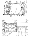
- La figure 3 est une vue de dessus en coupe, selon la ligne A-A, de la figure 1.
- La figure 4 est une vue de dessus d'un second mode de réalisation du dispositif élévateur comprenant trois blocs locomoteurs associés à un pied de la plateforme.
- La figure 5 est une vue de face d'un mode de réalisation perfectionnant celui de la figure 1.
- La figure 6 est une coupe selon B-B de la figure 5.
- La figure 7 est une variante de la figure 5.
- La figure 8 est une coupe selon C-C de la figure 7.
- La figure 9 est une vue d'un mode de réalisation perfectionnant celui de la figure 4.
- La figure 10 est une vue d'un mode de réalisation perfectionnant celui de la figure 1.
- Si l'on se réfère aux figures 1 à 10, la plateforme comporte un pont 1 horizontal qui constitue un caisson flottable. Ce pont 1 est supporté par des pieds 2 dont le nombre est au moins égal à 3. Les pieds représentés sur les figures ont une section cylindrique mais une forme polygonale pourrait convenir. Ces pieds sont construits à partir de tubes mais ils pourraient être construits différemment. Chaque pied passe dans une ouverture du pont de la plateforme où il est guidé par un ensemble de patins.
- Des montants 3 sont fixés sur chaque pied 2 parrallèlement à son axe longitudinal 21. Deux crémaillères 31 et 32 à dentures droites sont taillées dans chaque montant 3. Les plans enveloppant les sommets et les pieds des dents constituant ces deux crémaillères sont parallèles, les dents étant elles-m êmes parallèles. Ces crémaillères sont symétriques par rapport au plan de symétrie 37 du montant et sont opposées vers l'extérieur.
- Le plan de symétrie 37 des deux crémaillères 31 et 32 taillées sur chaque montant passe par l'axe de symétrie 21 du pied correspondant. Chaque montant est pourvu de deux pistes de guidage 33 et 34 et d'une piste de guidage latérale 35. Les pistes de guidage 33 et 34 sont planes et parallèles aux dents des crémaillères et la piste latérale 35 est plane et perpendiculaire à ces mêmes dents. Chaque montant a donc la forme générale d'un T, les pistes de guidage 33 et 34 étant logées entre les dents des crémaillères et la périphérie du pied associé. La section en T des montants est adaptée au guidage défini ci-dessus mais d'autres sections peuvent être retenues.
- Chaque montant 3 pourvu de deux crémaillères coopère avec un bloc locomoteur repéré dans son ensemble par la référence 5. Chaque bloc locomoteur 5 comporte un châssis 51. Il est équipé d'un jeu de pignons 55 engrenant sur la crémaillère 31 du montant associé et d'un jeu de pignons 56 engrenant sur la crémaillère 32 du même montant. Les pignons 55 et 56 sont montés sur des arbres guidés en rotation dans le châssis 51. Du fait de la disposition de crémaillères 31 et 32, le jeu de pignons 55 et le jeu de pignons 56 de chaque bloc locomoteur encadrent le montant associé 3.
- Les réactions entre les pignons 55 et les dents de la crémaillère 31 sont équilibrées par les réactions entre les pignons 56 et les dents de la crémaillère 32. L'égalité de ces réactions assure le centrage de chaque bloc locomoteur par rapport au montant associé. Les axes des pignons 55 et 56 d'une même bloc locomoteur sont parallèles entre eux. Les axes des pignons 55 d'un bloc locomoteur sont contenus dans le plan des axes des pignons 56 du bloc locomoteur opposé.
- Chaque pignon 55 ou 56 est accouplé à un réducteur entraîné par un moteur 57 ou 58 respectivement.
- Dans les modes de réalisation des figures 1 à 3, 5 et 6, 7 et 8, 10, chaque pied est solidaire de deux montants 3 associés chacun à un bloc locomoteur 5. Les deux montants 3 associés sont disposés à 180° l'un de l'autre et sont symétriques par rapport à l'axe longitudinal 21 du pied 2. Dans les modes de réalisation de la figure 4 ou de la figure 9, chaque pied est solidaire de trois montants 3 disposés à 1200 l'un par rapport à l'autre, autour de l'axe longitudinal 21 du pied 2.
- Le guidage relatif du châssis par rapport au plan de symétrie 37 des dentures est assuré par les réactions d'engrènement. Chaque châssis de bloc locomoteur est associé à des moyens qui équilibrent le couple de renversement important qui est engendré par l'effort transmis entre les blocs locomoteurs et le pont et qui l'assujettissent à suivre le pied associé. Chaque châssis de bloc locomoteur est relié à au moins un autre châssis de bloc locomoteur par au moins trois tirants horizontaux situés de part et d'autre du plan de symétrie 37 du montant qui passe par l'axe longitudinal 21 du pied.
- Dans les modes de réalisation des figures 1 à 3, 5 et 6, 7 et 8, 10 les deux blocs locomoteurs opposés par rapport à l'axe d'un pied sont reliés l'un à l'autre par trois tirants horizontaux 81, 82, 83, qui assurent l'équilibre des couples de renversement. Les trois tirants qui sont attelés à chaque bloc locomoteur sont parallèles aux dents des crémaillères et aux axes des pignons 55 et 56. Chacun des tirants est relié, par une articulation, autour d'un axe fixe du châssis d'un bloc locomoteur et est relié, par une articulation, autour d'un axe fixe du chassis du bloc locomoteur opposé. L'une au moins des deux articulations de chaque tirant est une articulation à rotule. Les tirants de liaison des deux blocs locomoteurs sont au nombre de trois de manière que le système soit isostatique. Le tirant 83 est disposé d'un côté du pied et du plan de symétrie 37, les tirants 82 et 81 étant disposés du côté opposé. Le tirant 83 pourrait être remplacé par deux tirants articulés chacun à l'un des blocs et d'autre part à un balancier dont l'axe serait articulé à l'autre bloc locomoteur. L'entraxe des articulations du tirant 81 est égal à l'entraxe des articulations du tirant 82 et à l'entraxe des articulations du tirant 83. L'ensemble formé par les deux blocs locomoteurs reliés par les tirants 81 et 82 constitue sensiblement un parallèlogramme déformable.
- Dans le mode de réalisation de la figure 4 ou de la figure 9, chaque bloc locomoteur est attelé à deux blocs locomoteurs par quatre tirants horizontaux 81 et 82. Deux tirants 81-82 s'étendent d'un côté du plan de symétrie 37 du montant, deux autres tirants 81-82 s'étendant du côté opposé à ce plan de symétrie. Les blocs locomoteurs sont reliés deux à deux par deux tirants horizontaux, l'un inférieur 82, l'autre supérieur 81. Chaque tirant s'accroche par deux articulations à rotule à deux blocs locomoteurs.
- Dans chaque mode de réalisation, un des blocs locomoteurs est relié au pont par l'intermédiaire d'une barre d'attelage 85. Cette barre 85 est reliée à-une extrémité au châssis du bloc locomoteur par une articulation et est reliée à son autre extrémité au pont de la plateforme par une articulation. L'une au moins des articulations est à rotule. De préférence cette barre 85 est parallèle aux tirants 81 à 83. L'articulation d'accrochage de cette barre sur le châssis d'un bloc locomoteur est éloignée de plan de symétrie des dentures du montant.
- Chaque bloc locomoteur est équipé d'organes de guidage 52 et 53 qui encadrent le montant 3 et sont susceptibles de guider son châssis par rapport au plan de symétrie 37 dans dentures des crémaillères. Ces organes de guidage 52 dont le nombre est au moins égal à 2 coopérent avec la piste de guidage 33 parallèle aux dents de crémaillères et au plan de symétrie 37. Les organes de guidage 53 dont le nombre est au moins égal à 2 coopèrant avec la piste de guidage 34 opposée. Les deux organes de guidage 52 associés à la piste 33 sont disposés l'un au dessus de l'autre et les deux organes de guidage 53 associés à la piste 34 sont également disposés l'un au dessus de l'autre.
- Chaque bloc locomoteur comporte au moins un organe de guidage 54 qui coopère avec la piste latérale de guidage 35 du montant associé. Cette piste est perpendiculaire au plan de symétrie 37 et aux dents des crémaillères. De préférence le nombre d'organes de guidage 54 montés sur le châssis d'un bloc locomoteur est au moins égal à deux.
- Les organes de guidage 52-53-54 sont par exemple constitués par des patins ou par des galets.
- Le pont est suspendu aux blocs locomoteurs d'un même pied par un système de suspension articulée relié à chaque bloc locomoteur par une articulation 41 ou 44 transmettant les efforts et comprenant au moins deux bielles de suspension 4 qui relient directement ou non les blocs locomoteurs et le pont.
- La ligne de force verticale passant par l'articulation de liaison 41 ou 44 de chaque bloc locomoteur avec le système de suspension articulé et par le plan de symétrie 37 est située à une distance plus grande, par rapport à l'axe 21 du pied, que la ligne de force 38 de la crémaillère (ligne de la résultante des efforts verticaux appliqués à la crémaillère). De ce fait un couple de renversement tend à faire pivoter chaque bloc locomoteur autour d'un axe perpendiculaire au plan de symétrie 37 du montant qui passe par l'axe longitudinal 21 du pied. Ce couple dépend de la distance d entre l'articulation 41 ou 44 et la ligne de force 38.
- Dans les modes de réalisation des figures 1 à 4, le système de suspension articulé comporte deux bielles de suspension 4 qui s'étendent chacune verticalement à côté d'un montant 3. L'axe longitudinal de chaque bielle est sensiblement situé dans le plan de symétrie 37 des deux crémaillères de ce montant et passe par l'articulation de liaison 41. Chaque bielle est liée au châssis de bloc locomoteur par l'intermédiaire de ladite articulation 41 qui est rotulante et comprend un axe engagé dans une chape solidaire du châssis. Elle est attachée au pont par l'intermédiaire d'une articulation rotulante 42 composée d'un axe lié à une pièce d'ancrage solidaire du pont. L'axe longitudinal de symétrie 43 de la bielle qui passe par les axes 41 et 42 est plus écarté de la périphérie du pied 2 que le plan médian 36 des crémaillères 31 et 32 (plan perpendiculaire aux dents des crémaillères et passant par leurs milieux). Chaque bloc locomoteur est soumis à un couple de renversement qui dépendra de l'effort transmis et de la distance d entre l'axe de symétrie de la bielle et le plan médian défini ci-dessus. Le couple de renversement tend à faire pivoter le bloc locomoteur autour d'un axe parallèle au plan médian 36.
- Dans le mode de réalisation de figures 5 à 9, le système de suspension articulé comprend au moins un anneau articulé 91 et 92. Il est lié aux blocs locomoteurs 5 par les articulations de liaison 41 ou 44 situées chacune dans un plan de symétrie 37 d'un montant. Chaque anneau d'articulation 91, 92 est relié à au moins deux bielles verticales qui le relient, de manière articulée, soit aux blocs locomoteurs, soit au pont, soit à un autre anneau.
- Dans le mode de réalisation de figures 5 et 6, les bielles de suspension 4 sont articulées à un cadre ou anneau d'équilibrage 91 qui entoure le pied 2. Cet anneau est relié par deux bielles 4 aux blocs locomoteurs et est lui-même relié par deux bielles 6 au pont. Les articulations des bielles 4 sur l'anneau 91 sont diamètralement opposées. Les articulations des bielles 4 et 6 sur l'anneau 91 sont sur des diamètres orthogonaux.
- Dans le mode de réalisation des figures 7 et 8, l'anneau 91 est monté au-dessus des blocs- locomoteurs. Il s'appuie sur les blocs locomoteurs soit par deux appuis à rotule 44, soit par deux bielles de suspension 4 articulées chacune à un châssis de bloc locomoteur par l'articulation 41 et à l'anneau 91. Les appuis 44 ou les bielles 4 sont disposées symétriquement par rapport à l'axe 21 du pied dans les plans de symétrie 37 des montants. Des bielles de suspension 6 sont articulées à l'anneau 91 et au pont 1. Elles dont disposées symétriquement par rapport à l'axe 21 du pied et orthogonalement par rapport aux appuis 44 ou aux bielles 4.
- Dans le mode de réalisation de la figure 9, le dispositif comporte trois blocs locomoteurs autour du pied et le système de suspension articulé comprend deux anneaux 91 et 92. L'anneau 91 est reliè aux trois blocs moteurs par les bielles 4 de suspension dont les articulations de liaison 41 sont situées dans les plans de symétrie 37. Elles sont articulées sur l'anneau 91 et sont disposées à 120° l'une de l'autre. L'anneau 91 et l'anneau 92 sont reliés l'un à l'autre par deux bielles 6 symétriques par rapport à l'axe 21 du pied. L'anneau 92 est relié au pont par deux bielles 7 articulées. Les articulations des bielles 6 sur l'anneau 92 et les articulations des bielles 7 sur ce même anneau sont situées sur deux diamètres orthogonaux. Les articulations des bielles 6 sur l'anneau 91 sont situées sur un diamètre parallèle à la corde réunissant les articulations de deux des bielles 4 à ce même anneau 91.
- Dans le mode de réalisation de la figure 10, chacune des bielles de suspension 4 est attelée par une articulation rotulante à un retour d'équerre comprenant une manivelle 101 et une manivelle 102. Les deux manivelles 101 et 102 sont solidaires d'un arbre 103 guidé horizontalement dans des paliers fixés au pont. Les deux arbres 103 sont disposés parallèlement à égale distance de l'axe 21 du pied 2 et des bielles 4. Les manivelles 102 des deux retours d'équerre sont parallèles entre elles. Elles sont reliées par un tirant horizontal 104. Ce système articulé à tringlerie comprenant deux renvois d'équerre assure l'équilibrage des efforts entre les deux blocs locomoteurs.
- Le fonctionnement du dispositif élévateur va maintenant être expliqué.
- Les pignons 55 et 56 sont entraînés en rotation simultanément de manière à déplacer les châssis 51 le long des montants 3. Lorsque le pont flotte et que les pieds sont relevés, les bielles 4 sont soumises à des efforts. Dès que les pieds reposent sur le fond marin et que la plateforme et au-dessus de l'eau, les bielles 4 sont soumises à des efforts de sens inverse.
- Les couples de renversement appliqués aux châssis de blocs locomoteurs associés à un pied introduisent un effort passant par les articulations 41 ou 44. Ces couples sont encaissés par les tirants 81-82-83. Ainsi dans le mode de réalisation des figures 1, 2 et 3, lorsque le pont est soulevé par rapport aux pieds, le tirant supérieur 81 est en traction, le tirant inférieur 82 étant en compression. Inversement lorsque les pieds sont soulevés par rapport au pont, le tirant supérieur 81 est en compression, le tirant inférieur 82 étant en traction.
- Grâce aux articulations des tirants et de la barre d'attelage, chaque bloc locomoteur peut suivre les déplacements horizontaux du pied associé. La barre d'attelage 85 empêche les blocs locomoteurs de tourner. Les patins de guidage 54 contribuent au centrage des pignons en face des crémaillères. Les organes de guidage 52 et 53 interviennent en cas de déséquilibrage des couples d'entraînement des pignons moteurs.
- Le mécanisme de suspension articulé comprenant un ou deux anneaux autorise les oscillations des blocs locomoteurs qui peuvent suivre les oscillations du pied associé. Cette solution évite une surcharge sur les pignons lors du maintien de la plateforme en position de travail fixe assurée par serrage des freins ou éventuellement par verrouillage.
- Le dispositif élévateur s'applique aussi à des pieds dont les montants ne comportent chacun qu'une seule crémaillère, pourvu que les points d'application des efforts entre le système de suspension et les blocs locomoteurs soient situés dans les plans de symétrie des montants.
Claims (8)
Applications Claiming Priority (2)
| Application Number | Priority Date | Filing Date | Title |
|---|---|---|---|
| FR7834358A FR2443537A1 (fr) | 1978-12-06 | 1978-12-06 | Dispositif elevateur de plate-forme marine |
| FR7834358 | 1978-12-06 |
Publications (2)
| Publication Number | Publication Date |
|---|---|
| EP0020686A1 EP0020686A1 (fr) | 1981-01-07 |
| EP0020686B1 true EP0020686B1 (fr) | 1984-10-31 |
Family
ID=9215753
Family Applications (1)
| Application Number | Title | Priority Date | Filing Date |
|---|---|---|---|
| EP80900042A Expired EP0020686B1 (fr) | 1978-12-06 | 1980-06-17 | Dispositif elevateur de plateforme marine |
Country Status (7)
| Country | Link |
|---|---|
| US (1) | US4386757A (fr) |
| EP (1) | EP0020686B1 (fr) |
| JP (1) | JPS55501029A (fr) |
| DE (1) | DE2967285D1 (fr) |
| FR (1) | FR2443537A1 (fr) |
| SU (1) | SU1037835A3 (fr) |
| WO (1) | WO1980001181A1 (fr) |
Families Citing this family (15)
| Publication number | Priority date | Publication date | Assignee | Title |
|---|---|---|---|---|
| FR2492029A1 (fr) * | 1980-10-13 | 1982-04-16 | Francois Durand | Bloc pignons autoalignant et autobasculant pour patte de plate-forme auto-elevatrice |
| NL8103452A (nl) * | 1981-07-21 | 1983-02-16 | Rsv Gusto Eng Bv | Hefinrichting voor een kunstmatig eiland of werkplatform. |
| NO160387C (no) * | 1986-06-03 | 1989-04-12 | Maritime Hydraulics As | Innretning ved en heiseanordning, spesielt for et boretaarn |
| FR2643401B1 (fr) * | 1989-02-22 | 1995-05-05 | Brissonneau & Lotz | Mecanismes de manoeuvre de plateformes de forage auto-elevatrices, et plateformes munies de ces mecanismes |
| IT1230186B (it) * | 1989-04-18 | 1991-10-18 | Snam Progetti | Piattaforma isola offshore a piu' elementi componibili per lo stoccaggio, l'attracco e il caricamento diretto di navi e procedimento per la sua installazione, rimozione e rilocazione. |
| RU2499098C2 (ru) * | 2011-12-05 | 2013-11-20 | Закрытое акционерное общество Научно-проектно внедренческое общество "НГС - оргпроектэкономика" | Ледостойкая самоподъемная платформа для замерзающего мелководья и способ ее монтажа |
| KR101359645B1 (ko) * | 2012-04-04 | 2014-02-06 | 삼성중공업 주식회사 | 부유식 구조물의 레그 지지장치 및 부유식 구조물 |
| US9145956B2 (en) | 2013-01-25 | 2015-09-29 | Gustomsc Resources B.V. | Torque sharing drive and torque sharing process |
| CN103147430B (zh) * | 2013-03-14 | 2015-09-23 | 广东精铟海洋工程股份有限公司 | 一种多功能环梁升降装置 |
| CN103452088B (zh) * | 2013-09-12 | 2015-08-05 | 中国海洋石油总公司 | 海上平台的顶升装置 |
| US20150129529A1 (en) * | 2013-11-13 | 2015-05-14 | Lee David Screaton | Marine lifting apparatus |
| US9531237B2 (en) | 2013-12-19 | 2016-12-27 | Gustomsc Resources B.V. | Dual rack output pinion drive |
| CN104120700B (zh) * | 2014-08-11 | 2016-02-24 | 武汉船用机械有限责任公司 | 一种液压插销升降装置 |
| SG11201608376QA (en) * | 2015-08-31 | 2017-04-27 | Keppel Offshore & Marine Technology Ct Pte Ltd | Fixation system for hydraulic jacking system |
| CN106628032B (zh) * | 2015-10-30 | 2019-08-23 | 中石化石油工程技术服务有限公司 | 一种悬臂梁移动与锁紧装置 |
Family Cites Families (13)
| Publication number | Priority date | Publication date | Assignee | Title |
|---|---|---|---|---|
| US2944403A (en) * | 1953-09-04 | 1960-07-12 | Raymond Int Inc | Hydraulic jacking assembly for marine platforms |
| FR1307277A (fr) * | 1961-07-25 | 1962-10-26 | Francois Durand | Dispositif pour la commande d'une roue dentée par deux pignons avec adaptation automatique de la portance des dents de chaque pignon sur la couronne |
| US3565400A (en) * | 1967-08-12 | 1971-02-23 | Mitsui Shipbuilding Eng | Apparatus for raising and lowering a heavy weight |
| FR1579531A (fr) * | 1968-03-13 | 1969-08-29 | ||
| GB1251571A (fr) * | 1969-08-27 | 1971-10-27 | ||
| BE758930A (fr) * | 1969-11-14 | 1971-04-16 | Armco Steel Corp | Structure supportée par des pylones, installée au large, avec appareils de levage |
| US3743247A (en) * | 1969-11-14 | 1973-07-03 | Armco Steel Corp | Leg supported offshore structure with jacking apparatus |
| DE2103803C3 (de) * | 1970-02-02 | 1974-09-19 | Mitsui Shipbuilding And Engineering Co. Ltd., Tokio | Kletterhubwerk |
| DE2130781B2 (de) * | 1971-06-22 | 1974-08-15 | Wgw Westdeutsche Getriebe- Und Kupplungswerke Gmbh, 4630 Bochum | Mehrfach-Antrieb für einen Zahnkranz, mit mehreren Trägern für die Antriebsritzel |
| DE2319931A1 (de) * | 1973-04-19 | 1974-11-07 | Gewerk Eisenhuette Westfalia | Einrichtung zum heben und senken einer mit hubbeinen versehenen arbeitsplattform od. dgl |
| CH590975A5 (en) * | 1975-01-24 | 1977-08-31 | Ishall Sa | Rack and pinion platform elevator for drilling rig - has rack on rig leg and pinion housing mounted on platform via telescopic strain stays |
| NL172474C (nl) * | 1976-06-08 | 1983-09-01 | Ihc Holland Nv | Kunstmatig eiland met een hefmechanisme voor dit eiland. |
| US4203576A (en) * | 1978-07-11 | 1980-05-20 | Sutton John R | Elevating assembly for an offshore platform |
-
1978
- 1978-12-06 FR FR7834358A patent/FR2443537A1/fr active Granted
-
1979
- 1979-12-05 WO PCT/FR1979/000122 patent/WO1980001181A1/fr active IP Right Grant
- 1979-12-05 JP JP50009379A patent/JPS55501029A/ja active Pending
- 1979-12-05 DE DE8080900042T patent/DE2967285D1/de not_active Expired
- 1979-12-05 US US06/244,131 patent/US4386757A/en not_active Expired - Lifetime
-
1980
- 1980-06-17 EP EP80900042A patent/EP0020686B1/fr not_active Expired
- 1980-08-04 SU SU802955205A patent/SU1037835A3/ru active
Also Published As
| Publication number | Publication date |
|---|---|
| SU1037835A3 (ru) | 1983-08-23 |
| US4386757A (en) | 1983-06-07 |
| DE2967285D1 (de) | 1984-12-06 |
| WO1980001181A1 (fr) | 1980-06-12 |
| EP0020686A1 (fr) | 1981-01-07 |
| FR2443537B1 (fr) | 1982-11-19 |
| JPS55501029A (fr) | 1980-11-27 |
| FR2443537A1 (fr) | 1980-07-04 |
Similar Documents
| Publication | Publication Date | Title |
|---|---|---|
| EP0020686B1 (fr) | Dispositif elevateur de plateforme marine | |
| EP0729399B1 (fr) | Systeme telescopique | |
| CN102156054B (zh) | 一种足式机器人行走能力试验装置 | |
| FR2463258A1 (fr) | Perforatrice guidee par affut ou par mat | |
| JP2021102524A (ja) | 改良された可動式カウンタウエイトを備えた吊り上げクレーン | |
| US3820820A (en) | Pedal drive | |
| WO2017072449A1 (fr) | Portique d'assemblage de moteur | |
| JPH07212930A (ja) | 棒状の要素に沿って垂直移動するためのクライミング運搬具 | |
| FR2551041A1 (fr) | Dispositif d'articulation pour une grue a tour possedant une position inactive ou de rangement | |
| US3840225A (en) | Amusement park ride | |
| CN107366214A (zh) | 用于联接地面加工机的机架与工作装置的方法、地面加工装置和用于该方法的连接设备 | |
| EP0269669A1 (fr) | Agencement d'un dispositif de levage, notamment pour derrick | |
| EP0425339A1 (fr) | Dispositif de suspension et de manutention intégré dans les jambes d'une plate-forme pétrolière auto-élévatrice | |
| FR2521969A1 (fr) | Machine transportable sur vehicule, pouvant elever une nacelle a des hauteurs differentes | |
| US2905262A (en) | Mast control and deck leveling means for vehicle supported mast structure | |
| FR2577584A1 (fr) | Structure rigide reglable en longueur, notamment pour plate-forme petroliere. | |
| FR2485451A1 (fr) | Vehicule tracteur enjambeur a palonniers sustentateurs pour applications diverses | |
| CN112814625B (zh) | 一种石油开采用钢绳抽油机 | |
| FR2579558A1 (fr) | Organe pour l'accouplement et le desaccouplement frequents d'un navire a une structure d'amarrage, et dispositif d'amarrage comportant de tels organes | |
| FR2467170A1 (fr) | Elevateur a double effet pour patte de plate-forme auto-elevatrice | |
| CH428137A (fr) | Portique de manutention | |
| FR2476053A2 (fr) | Elevateur a double effet | |
| FR2467169A1 (fr) | Grue a tour | |
| US2230759A (en) | Self-propelled apparatus | |
| WO2018024486A1 (fr) | Dispositif pour bassin comportant une bequille |
Legal Events
| Date | Code | Title | Description |
|---|---|---|---|
| PUAI | Public reference made under article 153(3) epc to a published international application that has entered the european phase |
Free format text: ORIGINAL CODE: 0009012 |
|
| 17P | Request for examination filed |
Effective date: 19800909 |
|
| AK | Designated contracting states |
Designated state(s): DE FR GB NL |
|
| GRAA | (expected) grant |
Free format text: ORIGINAL CODE: 0009210 |
|
| AK | Designated contracting states |
Designated state(s): DE FR GB NL |
|
| REF | Corresponds to: |
Ref document number: 2967285 Country of ref document: DE Date of ref document: 19841206 |
|
| PGFP | Annual fee paid to national office [announced via postgrant information from national office to epo] |
Ref country code: FR Payment date: 19841221 Year of fee payment: 6 |
|
| PGFP | Annual fee paid to national office [announced via postgrant information from national office to epo] |
Ref country code: DE Payment date: 19850122 Year of fee payment: 6 |
|
| PLBE | No opposition filed within time limit |
Free format text: ORIGINAL CODE: 0009261 |
|
| STAA | Information on the status of an ep patent application or granted ep patent |
Free format text: STATUS: NO OPPOSITION FILED WITHIN TIME LIMIT |
|
| 26N | No opposition filed | ||
| GBPC | Gb: european patent ceased through non-payment of renewal fee | ||
| PG25 | Lapsed in a contracting state [announced via postgrant information from national office to epo] |
Ref country code: FR Free format text: LAPSE BECAUSE OF NON-PAYMENT OF DUE FEES Effective date: 19880831 |
|
| PG25 | Lapsed in a contracting state [announced via postgrant information from national office to epo] |
Ref country code: DE Effective date: 19880901 |
|
| REG | Reference to a national code |
Ref country code: FR Ref legal event code: ST |
|
| PG25 | Lapsed in a contracting state [announced via postgrant information from national office to epo] |
Ref country code: GB Free format text: LAPSE BECAUSE OF NON-PAYMENT OF DUE FEES Effective date: 19881118 |
|
| PGFP | Annual fee paid to national office [announced via postgrant information from national office to epo] |
Ref country code: NL Payment date: 19981123 Year of fee payment: 20 |
|
| PG25 | Lapsed in a contracting state [announced via postgrant information from national office to epo] |
Ref country code: NL Free format text: LAPSE BECAUSE OF EXPIRATION OF PROTECTION Effective date: 19991205 |
|
| NLV7 | Nl: ceased due to reaching the maximum lifetime of a patent |
Effective date: 19991205 |