EP0020264A1 - Wärmetauscher des Teil-Modul-Typs für Kernreaktor - Google Patents
Wärmetauscher des Teil-Modul-Typs für Kernreaktor Download PDFInfo
- Publication number
- EP0020264A1 EP0020264A1 EP80400749A EP80400749A EP0020264A1 EP 0020264 A1 EP0020264 A1 EP 0020264A1 EP 80400749 A EP80400749 A EP 80400749A EP 80400749 A EP80400749 A EP 80400749A EP 0020264 A1 EP0020264 A1 EP 0020264A1
- Authority
- EP
- European Patent Office
- Prior art keywords
- base plate
- support
- secondary fluid
- exchanger
- modules
- Prior art date
- Legal status (The legal status is an assumption and is not a legal conclusion. Google has not performed a legal analysis and makes no representation as to the accuracy of the status listed.)
- Granted
Links
Images


Classifications
-
- F—MECHANICAL ENGINEERING; LIGHTING; HEATING; WEAPONS; BLASTING
- F28—HEAT EXCHANGE IN GENERAL
- F28D—HEAT-EXCHANGE APPARATUS, NOT PROVIDED FOR IN ANOTHER SUBCLASS, IN WHICH THE HEAT-EXCHANGE MEDIA DO NOT COME INTO DIRECT CONTACT
- F28D1/00—Heat-exchange apparatus having stationary conduit assemblies for one heat-exchange medium only, the media being in contact with different sides of the conduit wall, in which the other heat-exchange medium is a large body of fluid, e.g. domestic or motor car radiators
- F28D1/02—Heat-exchange apparatus having stationary conduit assemblies for one heat-exchange medium only, the media being in contact with different sides of the conduit wall, in which the other heat-exchange medium is a large body of fluid, e.g. domestic or motor car radiators with heat-exchange conduits immersed in the body of fluid
- F28D1/0206—Heat exchangers immersed in a large body of liquid
- F28D1/0213—Heat exchangers immersed in a large body of liquid for heating or cooling a liquid in a tank
-
- G—PHYSICS
- G21—NUCLEAR PHYSICS; NUCLEAR ENGINEERING
- G21C—NUCLEAR REACTORS
- G21C1/00—Reactor types
- G21C1/02—Fast fission reactors, i.e. reactors not using a moderator ; Metal cooled reactors; Fast breeders
- G21C1/03—Fast fission reactors, i.e. reactors not using a moderator ; Metal cooled reactors; Fast breeders cooled by a coolant not essentially pressurised, e.g. pool-type reactors
-
- F—MECHANICAL ENGINEERING; LIGHTING; HEATING; WEAPONS; BLASTING
- F28—HEAT EXCHANGE IN GENERAL
- F28D—HEAT-EXCHANGE APPARATUS, NOT PROVIDED FOR IN ANOTHER SUBCLASS, IN WHICH THE HEAT-EXCHANGE MEDIA DO NOT COME INTO DIRECT CONTACT
- F28D21/00—Heat-exchange apparatus not covered by any of the groups F28D1/00 - F28D20/00
- F28D2021/0019—Other heat exchangers for particular applications; Heat exchange systems not otherwise provided for
- F28D2021/0054—Other heat exchangers for particular applications; Heat exchange systems not otherwise provided for for nuclear applications
-
- Y—GENERAL TAGGING OF NEW TECHNOLOGICAL DEVELOPMENTS; GENERAL TAGGING OF CROSS-SECTIONAL TECHNOLOGIES SPANNING OVER SEVERAL SECTIONS OF THE IPC; TECHNICAL SUBJECTS COVERED BY FORMER USPC CROSS-REFERENCE ART COLLECTIONS [XRACs] AND DIGESTS
- Y02—TECHNOLOGIES OR APPLICATIONS FOR MITIGATION OR ADAPTATION AGAINST CLIMATE CHANGE
- Y02E—REDUCTION OF GREENHOUSE GAS [GHG] EMISSIONS, RELATED TO ENERGY GENERATION, TRANSMISSION OR DISTRIBUTION
- Y02E30/00—Energy generation of nuclear origin
- Y02E30/30—Nuclear fission reactors
Definitions
- the present invention relates to a heat exchanger of the semi-modular type for a nuclear reactor and more particularly for a fast neutron nuclear reactor cooled by a liquid metal and of the integrated type.
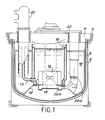
- Figure 1 a vertical sectional view of an integrated reactor.
- the main tank 6 which encloses the entire primary circuit is suspended from this slab 4 and doubled by a safety tank 8.
- the internal tank 10 Inside the main tank 6, there is an internal tank 10 which is supported by a platform 12 resting on the main tank.
- the internal tank separates, on the one hand, the hot liquid metal in general from the sodium, leaving the core 16 supported by the decking and, on the other hand, the cold metal contained in the annular space 18 comprised between the main tank 6 and the internal tank 10.
- the hot sodium leaving the core is taken up by pipes 19 which introduce the hot sodium leaving the core into intermediate exchangers 20.
- Pumps 22 also housed in the annular space 18 provide the circulation of the primary fluid, by reinjecting this liquid metal at the base of the heart into the bed base 14 by means of pipes 22b.
- the present invention relates to a heat exchanger capable of absorbing more easily than the exchangers according to the prior art the thermal expansions of which it is the seat due to the temperature differences of the two fluids circulating in the exchanger.
- the exchanger according to the invention can be described as semi-modular. Indeed, it is constituted by several exchange modules, but these exchange modules comprise a supply of common primary liquid metal and they are mechanically connected to each other.
- Each module includes a bundle of straight or “substantially” straight tubes.
- This latter expression means that the tubes can comprise, over a fraction of their length, in particular at their ends, portions in the form of a helix portion intended to give the tubes greater flexibility.
- the invention relates to a heat exchanger for a nuclear reactor, the vessel of which is closed by a slab, the exchanger being of the type comprising, inside an external shroud with vertical axis, a plurality of heat exchange modules with substantially straight tubes, each of these modules comprising an inlet chamber and an outlet chamber for secondary fluid and means for introducing and leaving the primary fluid in said exchange modules; it is characterized in that it comprises a base plate fixed on its periphery to said external ferrule, means for supporting said external ferrule by the slab, ferrules for supporting said modules, each ferrule passing through said base plate and being connected, on the one hand to the upper end of a module and, on the other hand, to said base plate, a plurality of pipes respectively for supplying and discharging the secondary fluid passing tightly through said plate base, an inlet manifold and an outlet manifold for the secondary fluid disposed inside said outer shroud above said base plate, said manifolds being connected respectively to the supply and discharge pipes of the secondary fluid , means for supporting
- the means su p porting manifolds comprise a support structure secured by its lower end to the base plate.
- the means for supporting the collectors comprise a support plate, the periphery of which is fixed to the external shell at the level of the means for supporting the external shell by the slab, and a support structure integral with its lower end of the support plate.
- the portions of the secondary fluid supply and discharge pipes included between the base plate and said manifolds have the shape of a propeller portion making an angle of approximately 180 °.
- the outlet chambers are located in the upper part of the modules exchange and acua .
- tion ev lines of the secondary fluid are arranged inside and coaxially to the rings support forces the latter ensuring the sealed penetration of the base plate by said secondary fluid discharge pipes.
- the ferrules play a double role.
- the exchanger comprises an outer ring 30 open at its lower end 30a and provided at its upper end with a support flange 30b.
- This outer shell 30 is extended by an upper dome 32 connected to the shell.
- the flange 30b which is held by a counter flange 30'b is supported on the slab 4 via the flange 33 and the support sleeve 34. It will be understood that thus the assembly of the vircle 30 and the dome 32 is supported by the flange 30b which rests on the slab 4.
- the internal space limited by the ferrule 30 is separated by a horizontal base plate 36 into a lower space 36a and an upper space 36b.
- the lower space contains the heat exchange modules such as 38
- the upper space contains the secondary fluid inlet and outlet manifolds (liquid sodium) circulating in the exchange modules 38.
- Each exchange module 38 is constituted in known manner by substantially straight exchange tubes 40 mounted between an upper tube plate 42 and a lower tube plate 44 connected respectively to outlet chambers 42a and inlet 44a.
- These exchange tubes are surrounded by an external ferrule 46 comprising a lower outlet window 48 for the primary fluid and an upper inlet window 50 for this same primary fluid.
- the inlet chamber 44a is connected to a supply line 52a which will be described in more detail later and the outlet chamber 42a is connected to a discharge line 54a which will also be described in more detail later.
- 56 have been symbolized by structures which make it possible to maintain the exchange tubes 40 of the exchange modules 48.
- each exchange module 38 is suspended by its upper part from the base plate 36.
- This suspension is advantageously carried out by means of a support ring 60 whose lower end 60a is welded to the outlet chamber 42a, and whose upper end 60b which passes through the plate 36 by a bore 62 is welded to a sleeve 61 itself secured to the base plate 36.
- each module d The exchange is rigidly supported by the base plate.
- the pipes 54a are arranged inside the ferrules 60. The sealed passage of the base plate 36 is thus carried out by the pipes 54a.
- pipes 72 make it possible to introduce argon into the upper region of the inlet window 50 of each module in order to possibly be able to stop the supply of primary sodium to the module in question.
- the conduits 52a have a curved part and rise up inside the ferrule 30 parallel to the modules.
- the tightness of the crossing of these pipes 52a through the base plate 36 is ensured by metallic expansion bellows 76 which are fixed on the one hand to the base plate 36 and on the other hand to the external wall of the pipes 52a.
- metallic expansion bellows 76 which are fixed on the one hand to the base plate 36 and on the other hand to the external wall of the pipes 52a.
- a cylindrical support structure 80 integral by its lower end 80a with the upper face of the base plate 36 supports on the one hand a cold collector 82, and on the other hand, a hot collector 84 which is disposed above the collector cold 82.
- the outlet pipes 54a of the hot secondary liquid metal are connected at their upper end to the hot manifold 84.
- these pipes 52a In the upper part of the shell 30, and in the dome 32, these pipes 52a have the shape of a portion d propeller making an angle of 180 °. They can thus absorb part of the expansion of these pipes due to the temperatures occurring in the exchanger.
- the hot collector is provided with a large pipe 86 for leaving the secondary hot liquid metal going to a steam generator as is well known in fast neutron reactors cooled by liquid sodium.
- the inlet conduits 52a of the cold secondary liquid metal are connected to the cold manifold 82 and each form inside the ferrule 30 a helix corresponding to an angle of 180 °.
- the cold collector 82 is provided with a large pipe 88 used for the introduction of the cold secondary liquid metal.
- the part 80 ′ of the central structure 80 provides the mechanical connection between the two cold and hot collectors, respectively.
- the hot manifold is provided at its upper part with a guide ring 90 which cooperates with a sleeve 92 integral with the upper part of the dome 32.
- the bore g e collectors and biological protection plates is no longer carried by the base plate 36 but through a plate Bracketing 110 disposed above the plate 36, at the flange bore g e 30b.
- the same reference numbers have been used to designate the elements identical to those of the first variant.
- the inlet 82 and outlet 84 collectors are supported by a support plate 110 pinched between the two parts of the support flange 30b belonging to the ferrule 30 and to the dome 32. More specifically, the inlet manifold 82 rests on the plate 110 by means of a support 112, the outlet manifold 84 being disposed above the inlet manifold and resting on the latter by through a central structure 114 similar to part 80 'in the variant of FIG. 2a.
- the collectors 82 and 84 are both arranged above the support plate 110 and the collector outlet 84 is always provided at its upper part with a ferrule 90 received in a sleeve 92 integral with the upper part of dome 32.
- the biological protection plates 94 are suspended from the plate bore 110 g e for example by means of rods 116 provided with suitable spacers 118, the plates 94 being disposed at the faceplate 4 and above the base plate 36.
- supply lines 52a and discharge 52b pass through suitable notches formed in the support plate 110.
- a spacer assembly 100 which includes a central rod 102 suspended in below the base plate 36 and the radial fins 104 ending in portions of tubes 106 which ensure the mutual setting of the introduction pipes 70, thus in particular avoiding the vibrations of these pipes.
- the first intervention consists of locking an exchange module inside the tank itself.
- the second intervention consists in the removal of an intermediate exchanger for a maintenance operation outside the nuclear reactor vessel.
- the large pipes 86 and 88 are cut and the intermediate exchanger is extracted from the tank by detaching the flange 30b.
- the ferrule 30 is cut approximately 300 mm above the base plate 36.
- the conduits 52a and 54a are also cut.
- the weld of the support ring 60 is ground on the sleeve 61 secured to the base plate 36.
- the module 38 can then be deposited on which it is necessary to intervene.
- the semi-modular exchanger according to the invention has many advantages compared to those of the prior art.
- the thermal expansions of the secondary inlet and outlet pipes are better absorbed without, however, complicating the structure.
- the exchanger has better behavior in the event of earthquakes to which the reactor would be subjected.
Landscapes
- Engineering & Computer Science (AREA)
- Physics & Mathematics (AREA)
- General Engineering & Computer Science (AREA)
- Thermal Sciences (AREA)
- Mechanical Engineering (AREA)
- Plasma & Fusion (AREA)
- High Energy & Nuclear Physics (AREA)
- Heat-Exchange Devices With Radiators And Conduit Assemblies (AREA)
Applications Claiming Priority (2)
| Application Number | Priority Date | Filing Date | Title |
|---|---|---|---|
| FR7914000 | 1979-05-31 | ||
| FR7914000A FR2458132A1 (fr) | 1979-05-31 | 1979-05-31 | Echangeur de chaleur intermediaire du type semi-modulaire pour reacteur nucleaire |
Publications (2)
| Publication Number | Publication Date |
|---|---|
| EP0020264A1 true EP0020264A1 (de) | 1980-12-10 |
| EP0020264B1 EP0020264B1 (de) | 1984-05-09 |
Family
ID=9226114
Family Applications (1)
| Application Number | Title | Priority Date | Filing Date |
|---|---|---|---|
| EP80400749A Expired EP0020264B1 (de) | 1979-05-31 | 1980-05-28 | Wärmetauscher des Teil-Modul-Typs für Kernreaktor |
Country Status (6)
| Country | Link |
|---|---|
| US (1) | US4348354A (de) |
| EP (1) | EP0020264B1 (de) |
| JP (1) | JPS55162100A (de) |
| DE (1) | DE3067740D1 (de) |
| ES (1) | ES491994A0 (de) |
| FR (1) | FR2458132A1 (de) |
Cited By (2)
| Publication number | Priority date | Publication date | Assignee | Title |
|---|---|---|---|---|
| EP0345160A1 (de) * | 1988-06-02 | 1989-12-06 | Commissariat A L'energie Atomique | Flüssigmetallgekühlter Kernreaktor mit schnellen Neutronen |
| FR2632760A1 (fr) * | 1988-06-09 | 1989-12-15 | Novatome | Virole interne d'un reacteur nucleaire a neutrons rapides comportant un dispositif de protection thermique |
Families Citing this family (4)
| Publication number | Priority date | Publication date | Assignee | Title |
|---|---|---|---|---|
| FR2534408A1 (fr) * | 1982-10-07 | 1984-04-13 | Commissariat Energie Atomique | Reacteur a neutrons rapides refroidi par un metal liquide |
| US6235246B1 (en) * | 1998-01-05 | 2001-05-22 | Ifp North America, Inc. | Reactor having bellows expansion unit between catalyst addition/withdrawal conduit and grid plate |
| JP5904207B2 (ja) | 2010-11-08 | 2016-04-13 | ローレンス リバモア ナショナル セキュリティー, エルエルシー | ホーラム |
| US11143456B2 (en) * | 2016-07-29 | 2021-10-12 | Keyon Process Co., Ltd | Heat exchanger |
Citations (7)
| Publication number | Priority date | Publication date | Assignee | Title |
|---|---|---|---|---|
| FR1271202A (fr) * | 1960-07-28 | 1961-09-08 | Babcock & Wilcox France | Perfectionnements aux installations de récupération de la chaleur d'un fluide sous pression |
| FR1399180A (fr) * | 1964-06-18 | 1965-05-14 | Foster Wheeler Ltd | Générateurs de vapeur perfectionnés du type tubulaire, dans lesquels le fluide de chauffage est un métal liquéfié, comme le sodium, particulièrement avantageux pour les réacteurs nucléaires |
| FR2360057A1 (fr) * | 1976-07-29 | 1978-02-24 | Gen Atomic Co | Echangeur de chaleur tubulaire, notamment pour installations nucleaires |
| FR2369658A2 (fr) * | 1976-11-12 | 1978-05-26 | Sulzer Ag | Circuit de transfert de chaleur |
| FR2379881A1 (fr) * | 1977-02-04 | 1978-09-01 | Commissariat Energie Atomique | Bloc-pompe echangeur de chaleur pour reacteurs nucleaires |
| FR2385067A1 (fr) * | 1977-03-21 | 1978-10-20 | Commissariat Energie Atomique | Echangeur thermique annulaire |
| GB2004361A (en) * | 1977-09-14 | 1979-03-28 | Sulzer Ag | Heat exchanger especially recuperator for high temperature reactors |
Family Cites Families (2)
| Publication number | Priority date | Publication date | Assignee | Title |
|---|---|---|---|---|
| FR2335791A1 (fr) * | 1975-12-18 | 1977-07-15 | Stein Industrie | Echangeur de chaleur a plusieurs modules en parallele |
| US4173997A (en) * | 1977-02-23 | 1979-11-13 | Westinghouse Electric Corp. | Modular steam generator |
-
1979
- 1979-05-31 FR FR7914000A patent/FR2458132A1/fr active Granted
-
1980
- 1980-05-28 EP EP80400749A patent/EP0020264B1/de not_active Expired
- 1980-05-28 DE DE8080400749T patent/DE3067740D1/de not_active Expired
- 1980-05-30 ES ES491994A patent/ES491994A0/es active Granted
- 1980-05-30 JP JP7161280A patent/JPS55162100A/ja active Pending
- 1980-05-30 US US06/154,604 patent/US4348354A/en not_active Expired - Lifetime
Patent Citations (7)
| Publication number | Priority date | Publication date | Assignee | Title |
|---|---|---|---|---|
| FR1271202A (fr) * | 1960-07-28 | 1961-09-08 | Babcock & Wilcox France | Perfectionnements aux installations de récupération de la chaleur d'un fluide sous pression |
| FR1399180A (fr) * | 1964-06-18 | 1965-05-14 | Foster Wheeler Ltd | Générateurs de vapeur perfectionnés du type tubulaire, dans lesquels le fluide de chauffage est un métal liquéfié, comme le sodium, particulièrement avantageux pour les réacteurs nucléaires |
| FR2360057A1 (fr) * | 1976-07-29 | 1978-02-24 | Gen Atomic Co | Echangeur de chaleur tubulaire, notamment pour installations nucleaires |
| FR2369658A2 (fr) * | 1976-11-12 | 1978-05-26 | Sulzer Ag | Circuit de transfert de chaleur |
| FR2379881A1 (fr) * | 1977-02-04 | 1978-09-01 | Commissariat Energie Atomique | Bloc-pompe echangeur de chaleur pour reacteurs nucleaires |
| FR2385067A1 (fr) * | 1977-03-21 | 1978-10-20 | Commissariat Energie Atomique | Echangeur thermique annulaire |
| GB2004361A (en) * | 1977-09-14 | 1979-03-28 | Sulzer Ag | Heat exchanger especially recuperator for high temperature reactors |
Cited By (4)
| Publication number | Priority date | Publication date | Assignee | Title |
|---|---|---|---|---|
| EP0345160A1 (de) * | 1988-06-02 | 1989-12-06 | Commissariat A L'energie Atomique | Flüssigmetallgekühlter Kernreaktor mit schnellen Neutronen |
| FR2632440A1 (fr) * | 1988-06-02 | 1989-12-08 | Commissariat Energie Atomique | Reacteur nucleaire a neutrons rapides, refroidi par un metal liquide |
| FR2632760A1 (fr) * | 1988-06-09 | 1989-12-15 | Novatome | Virole interne d'un reacteur nucleaire a neutrons rapides comportant un dispositif de protection thermique |
| US5013521A (en) * | 1988-06-09 | 1991-05-07 | Novatome | Internal shell of a fast-neutron nuclear reactor comprising a thermal protection device |
Also Published As
| Publication number | Publication date |
|---|---|
| DE3067740D1 (en) | 1984-06-14 |
| EP0020264B1 (de) | 1984-05-09 |
| ES8105114A1 (es) | 1981-05-16 |
| FR2458132A1 (fr) | 1980-12-26 |
| FR2458132B1 (de) | 1982-01-15 |
| US4348354A (en) | 1982-09-07 |
| ES491994A0 (es) | 1981-05-16 |
| JPS55162100A (en) | 1980-12-17 |
Similar Documents
| Publication | Publication Date | Title |
|---|---|---|
| WO1994021979A1 (fr) | Dispositif d'echange thermique et procede de refroidissement de l'enceinte d'un tel dispositif | |
| FR2620559A1 (fr) | Reacteur nucleaire a metal liquide supporte par le fond | |
| EP0515669A1 (de) | Plattenwärmetauscher. | |
| EP0020264B1 (de) | Wärmetauscher des Teil-Modul-Typs für Kernreaktor | |
| EP0163564B1 (de) | Schneller Neutronenkernreaktor mit Dampferzeuger, integriert im Behälter | |
| EP0020265B1 (de) | Wärmeaustauscher für Kernreaktor | |
| EP0083545B1 (de) | Sicherheitsvorrichtung zur Ableitung der entstehenden Wärme beim Abschalten eines schnellen Brüters | |
| EP0173602B1 (de) | Notwärmetauscher zur Kühlung des Primärmittels eines Kernreaktors und Verfahren zu dessen Zusammenbau | |
| EP0006800B1 (de) | Mit flüssigem Metall gekühlter schneller Kernreaktor | |
| EP0018262B1 (de) | Schneller Kernreaktor mit einem zylindrischen Innenbehälter | |
| EP0173586B1 (de) | Wärmetauscher mit Rohrbündel, von einer zylindrischen Hülle umgeben, welche radial in einer äusseren Hülle festgehalten wird | |
| EP0117191B1 (de) | Dampferzeuger für einen flüssigmetallgekühlten nuklearen Reaktor | |
| FR2535510A1 (fr) | Dispositif de purification du metal liquide de refroidissement d'un reacteur nucleaire a neutrons rapides | |
| EP0108690B1 (de) | Wärmetauscher für Fluide hoher Temperatur, wobei eines der Fluide an der Oberseite des Wärmetauschers ein- und austritt | |
| EP0048672B1 (de) | Atomkernreaktor mit Wärmetauschern in integrierter Bauweise | |
| BE1007153A5 (fr) | Echangeur de chaleur a dispositif de maintien anti-sismique et de supportage anti-envol de l'enveloppe entourant le faisceau de tubes. | |
| EP0161949B1 (de) | Mit flüssigem Metall gekühlter Kernreaktor | |
| EP0206921B1 (de) | Wärmetauscher mit koaxialen U-Rohren und Zwischenkreislauf von neutralem Gas und schneller Neutronenreaktor mit solchem Wärmetauscher | |
| EP0006801A1 (de) | Mit flüssigem Metall gekühlter schneller Kernreaktor | |
| EP0064920B1 (de) | Vorrichtung zur Dampferzeugung und zur Ableitung von Wärme in einem schnellen Brüter | |
| EP0090743B1 (de) | Schutzvorrichtung gegen Wärme und Radiation für einen in einem Kernreaktorbehälter eingetauchten Wärmeübertrager | |
| EP0095428B1 (de) | Gaskühleinrichtung für den Druckbehälterdeckel eines Kernreaktors | |
| EP0156689B1 (de) | Schneller Kernreaktor mit hängendem Hauptbecken und Deckel | |
| EP0144256B1 (de) | Anordnung zur thermischen Abschirmung einer Komponente eines Kernreaktors mit schnellen Neutronen | |
| EP0082780A1 (de) | Dampferzeuger durch Wärmeaustauschung zwischen einem flüssigen, kalorienreichen Metall und Speisewasser |
Legal Events
| Date | Code | Title | Description |
|---|---|---|---|
| PUAI | Public reference made under article 153(3) epc to a published international application that has entered the european phase |
Free format text: ORIGINAL CODE: 0009012 |
|
| AK | Designated contracting states |
Designated state(s): BE DE FR GB IT NL |
|
| 17P | Request for examination filed |
Effective date: 19810507 |
|
| ITF | It: translation for a ep patent filed |
Owner name: JACOBACCI & PERANI S.P.A. |
|
| GRAA | (expected) grant |
Free format text: ORIGINAL CODE: 0009210 |
|
| PGFP | Annual fee paid to national office [announced via postgrant information from national office to epo] |
Ref country code: DE Payment date: 19840419 Year of fee payment: 5 |
|
| AK | Designated contracting states |
Designated state(s): BE DE FR GB IT NL |
|
| PGFP | Annual fee paid to national office [announced via postgrant information from national office to epo] |
Ref country code: FR Payment date: 19840524 Year of fee payment: 5 |
|
| REF | Corresponds to: |
Ref document number: 3067740 Country of ref document: DE Date of ref document: 19840614 |
|
| PGFP | Annual fee paid to national office [announced via postgrant information from national office to epo] |
Ref country code: BE Payment date: 19840630 Year of fee payment: 5 |
|
| PLBE | No opposition filed within time limit |
Free format text: ORIGINAL CODE: 0009261 |
|
| STAA | Information on the status of an ep patent application or granted ep patent |
Free format text: STATUS: NO OPPOSITION FILED WITHIN TIME LIMIT |
|
| 26N | No opposition filed | ||
| PGFP | Annual fee paid to national office [announced via postgrant information from national office to epo] |
Ref country code: NL Payment date: 19860531 Year of fee payment: 7 |
|
| BERE | Be: lapsed |
Owner name: COMMISSARIAT A L'ENERGIE ATOMIQUE ETABLISSEMENT D Effective date: 19870531 |
|
| PG25 | Lapsed in a contracting state [announced via postgrant information from national office to epo] |
Ref country code: NL Effective date: 19871201 |
|
| NLV4 | Nl: lapsed or anulled due to non-payment of the annual fee | ||
| PG25 | Lapsed in a contracting state [announced via postgrant information from national office to epo] |
Ref country code: FR Free format text: LAPSE BECAUSE OF NON-PAYMENT OF DUE FEES Effective date: 19880129 |
|
| PG25 | Lapsed in a contracting state [announced via postgrant information from national office to epo] |
Ref country code: DE Effective date: 19880202 |
|
| GBPC | Gb: european patent ceased through non-payment of renewal fee | ||
| REG | Reference to a national code |
Ref country code: FR Ref legal event code: ST |
|
| PG25 | Lapsed in a contracting state [announced via postgrant information from national office to epo] |
Ref country code: GB Free format text: LAPSE BECAUSE OF NON-PAYMENT OF DUE FEES Effective date: 19881118 |
|
| PG25 | Lapsed in a contracting state [announced via postgrant information from national office to epo] |
Ref country code: BE Effective date: 19890531 |