EP0090743B1 - Schutzvorrichtung gegen Wärme und Radiation für einen in einem Kernreaktorbehälter eingetauchten Wärmeübertrager - Google Patents
Schutzvorrichtung gegen Wärme und Radiation für einen in einem Kernreaktorbehälter eingetauchten Wärmeübertrager Download PDFInfo
- Publication number
- EP0090743B1 EP0090743B1 EP83400683A EP83400683A EP0090743B1 EP 0090743 B1 EP0090743 B1 EP 0090743B1 EP 83400683 A EP83400683 A EP 83400683A EP 83400683 A EP83400683 A EP 83400683A EP 0090743 B1 EP0090743 B1 EP 0090743B1
- Authority
- EP
- European Patent Office
- Prior art keywords
- sleeve
- flange
- slab
- exchanger
- ferrule
- Prior art date
- Legal status (The legal status is an assumption and is not a legal conclusion. Google has not performed a legal analysis and makes no representation as to the accuracy of the status listed.)
- Expired
Links
- 230000005855 radiation Effects 0.000 title claims description 19
- XKRFYHLGVUSROY-UHFFFAOYSA-N Argon Chemical compound [Ar] XKRFYHLGVUSROY-UHFFFAOYSA-N 0.000 claims description 10
- 230000002093 peripheral effect Effects 0.000 claims description 10
- 239000007787 solid Substances 0.000 claims description 9
- 229910000831 Steel Inorganic materials 0.000 claims description 8
- 239000010959 steel Substances 0.000 claims description 8
- 239000012530 fluid Substances 0.000 claims description 6
- 229910052786 argon Inorganic materials 0.000 claims description 5
- 229910001338 liquidmetal Inorganic materials 0.000 claims description 5
- 239000007789 gas Substances 0.000 claims description 4
- 229910052500 inorganic mineral Inorganic materials 0.000 claims description 3
- 239000012212 insulator Substances 0.000 claims description 3
- 239000011707 mineral Substances 0.000 claims description 3
- 238000010438 heat treatment Methods 0.000 claims description 2
- 230000002035 prolonged effect Effects 0.000 claims 1
- DGAQECJNVWCQMB-PUAWFVPOSA-M Ilexoside XXIX Chemical compound C[C@@H]1CC[C@@]2(CC[C@@]3(C(=CC[C@H]4[C@]3(CC[C@@H]5[C@@]4(CC[C@@H](C5(C)C)OS(=O)(=O)[O-])C)C)[C@@H]2[C@]1(C)O)C)C(=O)O[C@H]6[C@@H]([C@H]([C@@H]([C@H](O6)CO)O)O)O.[Na+] DGAQECJNVWCQMB-PUAWFVPOSA-M 0.000 description 31
- 229910052708 sodium Inorganic materials 0.000 description 31
- 239000011734 sodium Substances 0.000 description 31
- 239000007788 liquid Substances 0.000 description 15
- 238000009413 insulation Methods 0.000 description 10
- 230000004888 barrier function Effects 0.000 description 3
- 229910052751 metal Inorganic materials 0.000 description 3
- 239000002184 metal Substances 0.000 description 3
- 238000010276 construction Methods 0.000 description 2
- 239000011261 inert gas Substances 0.000 description 2
- 238000009434 installation Methods 0.000 description 2
- 230000001681 protective effect Effects 0.000 description 2
- 230000003471 anti-radiation Effects 0.000 description 1
- 238000000605 extraction Methods 0.000 description 1
- 239000011810 insulating material Substances 0.000 description 1
- 239000000463 material Substances 0.000 description 1
- 230000001869 rapid Effects 0.000 description 1
- 229910001220 stainless steel Inorganic materials 0.000 description 1
- 239000010935 stainless steel Substances 0.000 description 1
- 230000008646 thermal stress Effects 0.000 description 1
Images
Classifications
-
- G—PHYSICS
- G21—NUCLEAR PHYSICS; NUCLEAR ENGINEERING
- G21C—NUCLEAR REACTORS
- G21C11/00—Shielding structurally associated with the reactor
- G21C11/08—Thermal shields; Thermal linings, i.e. for dissipating heat from gamma radiation which would otherwise heat an outer biological shield ; Thermal insulation
-
- F—MECHANICAL ENGINEERING; LIGHTING; HEATING; WEAPONS; BLASTING
- F28—HEAT EXCHANGE IN GENERAL
- F28D—HEAT-EXCHANGE APPARATUS, NOT PROVIDED FOR IN ANOTHER SUBCLASS, IN WHICH THE HEAT-EXCHANGE MEDIA DO NOT COME INTO DIRECT CONTACT
- F28D7/00—Heat-exchange apparatus having stationary tubular conduit assemblies for both heat-exchange media, the media being in contact with different sides of a conduit wall
- F28D7/16—Heat-exchange apparatus having stationary tubular conduit assemblies for both heat-exchange media, the media being in contact with different sides of a conduit wall the conduits being arranged in parallel spaced relation
- F28D7/163—Heat-exchange apparatus having stationary tubular conduit assemblies for both heat-exchange media, the media being in contact with different sides of a conduit wall the conduits being arranged in parallel spaced relation with conduit assemblies having a particular shape, e.g. square or annular; with assemblies of conduits having different geometrical features; with multiple groups of conduits connected in series or parallel and arranged inside common casing
- F28D7/1669—Heat-exchange apparatus having stationary tubular conduit assemblies for both heat-exchange media, the media being in contact with different sides of a conduit wall the conduits being arranged in parallel spaced relation with conduit assemblies having a particular shape, e.g. square or annular; with assemblies of conduits having different geometrical features; with multiple groups of conduits connected in series or parallel and arranged inside common casing the conduit assemblies having an annular shape; the conduits being assembled around a central distribution tube
-
- F—MECHANICAL ENGINEERING; LIGHTING; HEATING; WEAPONS; BLASTING
- F28—HEAT EXCHANGE IN GENERAL
- F28D—HEAT-EXCHANGE APPARATUS, NOT PROVIDED FOR IN ANOTHER SUBCLASS, IN WHICH THE HEAT-EXCHANGE MEDIA DO NOT COME INTO DIRECT CONTACT
- F28D21/00—Heat-exchange apparatus not covered by any of the groups F28D1/00 - F28D20/00
- F28D2021/0019—Other heat exchangers for particular applications; Heat exchange systems not otherwise provided for
- F28D2021/0054—Other heat exchangers for particular applications; Heat exchange systems not otherwise provided for for nuclear applications
-
- Y—GENERAL TAGGING OF NEW TECHNOLOGICAL DEVELOPMENTS; GENERAL TAGGING OF CROSS-SECTIONAL TECHNOLOGIES SPANNING OVER SEVERAL SECTIONS OF THE IPC; TECHNICAL SUBJECTS COVERED BY FORMER USPC CROSS-REFERENCE ART COLLECTIONS [XRACs] AND DIGESTS
- Y02—TECHNOLOGIES OR APPLICATIONS FOR MITIGATION OR ADAPTATION AGAINST CLIMATE CHANGE
- Y02E—REDUCTION OF GREENHOUSE GAS [GHG] EMISSIONS, RELATED TO ENERGY GENERATION, TRANSMISSION OR DISTRIBUTION
- Y02E30/00—Energy generation of nuclear origin
- Y02E30/30—Nuclear fission reactors
Definitions
- the invention relates to a device for protection against heat and radiation for an intermediate heat exchanger immersed in a nuclear reactor vessel filled with liquid metal constituting the primary fluid of the reactor.
- Fast neutron nuclear reactors generally include a large main tank filled with liquid sodium surmounted by an inert gas such as argon and closed by a very thick horizontal slab in which openings are made for passage. reactor components.
- the primary pumps putting the liquid sodium filling the tank into circulation and the intermediate exchangers carrying out the heat exchange between the primary sodium filling the tank and the secondary sodium transporting the heat to the steam generators pass through the slab at l interior of large openings and rest on the reactor slab via a flange fixed to their upper parts.
- Intermediate heat exchangers have a large diameter lower part immersed in liquid sodium, so that the passage in the slab must have a diameter large enough to allow the establishment or extraction of the intermediate exchanger without difficulty.
- the secondary sodium first circulates from top to bottom in a duct located at the central part of the exchanger, then from bottom to top in a tube bundle where heat exchange takes place with the primary fluid.
- the hot secondary liquid sodium circulates from bottom to top in an annular duct limited to its central part by the downward circulation duct of the sodium and to its peripheral part by a ferrule with vertical axis constituting the envelope of the intermediate exchanger.
- this ferrule At the upper part of the exchanger, this ferrule 'splits into an internal ferrule inside which circulates the hot secondary sodium and into an external ferrule on which the flange of the exchanger is fixed.
- the internal ferrule and the external ferrule are connected to each other and to the upper part of the exchanger by a symmetrical connecting piece of revolution, the meridian of which has the shape of a Y.
- the object of the invention is therefore to propose a device for protection against heat and radiation for an intermediate heat exchanger immersed in a nuclear reactor vessel filled with liquid metal constituting the primary fluid of the reactor and passing through a very thick slab closing the tank on which the exchanger rests by means of a flange secured to its upper part, the exchanger comprising in its upper part an internal ferrule with vertical axis, inside which circulates secondary liquid metal of which the heating is ensured by the primary fluid and an external ferrule connected to the internal ferrule by a piece of Y-section and coaxial with it, a peripheral space being formed around the external ferrule, in the opening of passage of the slab and, the protective device comprising a ferrule coaxial with the internal and external ferrules fixed under the flange in the peripheral space around the external ferrule carrying at its upper part under the flange a means of annular thermal insulation, device which allows to effectively isolate the intermediate exchanger in its crossing of the slab both with regard to radiation and with regard to the heat given off by secondary sodium.
- the ferrule has at its lower part a massive annular piece of insulation against radiation of a section such that it occupies the largest part of the section of the peripheral space and the connecting piece in Y is disposed at the central part of the shell between the solid part and the thermal insulation means.
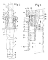
- an intermediate exchanger 1 is seen passing through the slab 2 of a fast neutron nuclear reactor through an opening 3 with a diameter slightly greater than the maximum diameter of the heat exchanger.
- Slab 2 closes the upper part of the tank containing liquid sodium up to level 4.
- the heat exchanger immersed in liquid sodium comprises in its submerged part a tubular bundle 6 communicating at one of its ends with a chamber lower bounded by a curved bottom 7 and at its upper part with an annular chamber limited by a ferrule with vertical axis 8 and by a vertical central duct 9.
- the central duct 9 opens at its upper part into the tubing 10 for the arrival of secondary liquid sodium.
- the annular chamber between the ferrule 8 and the conduit 9 communicates at its upper part with the tube 11 for the outlet of the heated secondary sodium.
- Tubing 10 and 11 are connected to the secondary sodium circuit of the nuclear reactor.
- the outer shell 12 surrounding the intermediate exchanger at its lower part has an inlet window 14 for the primary sodium in the heat exchanger and an outlet window 15 for this primary sodium.
- the primary sodium contained in the reactor vessel heats the secondary sodium circulating in the tube bundle 6.
- the secondary sodium entering the annular chamber limited by the ferrule 8 and the conduit 9 is therefore hot sodium which is brought to pass through the part of the exchanger disposed at the level of the slab 2 before it leaves via the pipe 11.
- a flange 18 secured to the ferrule 8 allows the heat exchanger to rest on the slab 2 by means of a support 19, a counter-flange 20 allowing the flange to be fixed on its support.
- the opening 3 of the slab is surrounded by a metal jacket 21 to which the flange support 19 is fixed by means of a fixing ring 23.
- the outer ferrule 8 is fixed to the flange 18. This ferrule 8 is split into an internal ferrule 8a and an external ferrule 8b by virtue of an annular connecting piece 25 whose meridian section has the shape of a Y.
- the hot secondary liquid sodium at the outlet of the tube bundle circulates from bottom to top in the annular duct formed by the ferrules 8 and 9 then by the ferrule 8a and the double ferrule 9.
- a ferrule 27 Under the flange 18, at the connection of the ferrule 8 is fixed a ferrule 27 by means of screws 28.
- This ferrule 27 is coaxial with the ferrule 8 and of a diameter slightly greater than that of this ferrule.
- the ferrule 27 is welded to a massive annular piece 30 of ordinary steel whose width is such that this piece occupies most of the annular space comprised between the coaxial ferrules 8 and 21.
- the ferrule 31 protects the passage of the slab 2 and the ferrule 21 against thermal radiation from the ferrule 8 inside which the hot sodium flows.
- the ferrule 27 provides protection against the thermal radiation of the ferrule 8. It is in this zone that the connecting part 25 is located between the ferrules 8, 8a and 8b.
- annular enclosure 32 At the upper part of the shell 27 and under the flange 18 is disposed an annular enclosure 32 to the interior of which is placed a metallic insulation consisting of separate elements forming a barrier to thermal radiation.
- the interior space of the annular enclosure 32 is filled with insulating argon. Tubes 34 assemble the parts of the enclosure 32 and the metal insulation.
- the outside diameter of the enclosure 32 is very slightly smaller than the inside diameter of the support 19 and of the shell 23.
- a metal elastic ring 35 is arranged composed of 3 sectors arranged at 120 ° around the ferrule 8 of the heat exchanger. This elastic ring makes it possible to limit the movements of convection gas in the space between the parts 8 and 27 and therefore the heat inputs in the upper part of the device.
- the main advantages of the device according to the invention are to allow excellent protection against heat and radiation of the part of the slab located in the vicinity of the crossing and of the area adjacent to the intermediate heat exchanger situated in the - above slab 2.
- This device is of a very simple structure and makes it possible to avoid thermal deformations of the Y-piece of connection prejudicial to good mechanical strength.
- the lower part of the device comprising the solid part 30 and the ferrule 31 can be constructed of ordinary steel, which reduces the cost of construction of the heat exchanger.
- the entire protective device which is not in contact with the liquid sodium can also be made of ordinary steel.
- the invention is not limited to the embodiment which has just been described, thus the solid part 30 can be made of a material other than ordinary steel.
- the metallic insulation inside the enclosure 32 can be made in any form or constituted by a set of discs forming an anti-radiation screen.
- This enclosure may include any device for filling and emptying the argon.
- the mineral insulation 26 disposed between the ferrules 8a and 8b can be constituted by blocks of any shape juxtaposed and arranged in the annular interval up to the level of the flange 18 or a little above.
- All the parts outside the shell 8 containing the liquid sodium can be made of ordinary non-stainless steel, which reduces the cost of construction of the heat exchanger.
- the device according to the invention applies to all the intermediate heat exchangers used in integrated type fast neutron nuclear reactors.
Landscapes
- Engineering & Computer Science (AREA)
- Physics & Mathematics (AREA)
- General Engineering & Computer Science (AREA)
- Health & Medical Sciences (AREA)
- Mechanical Engineering (AREA)
- Thermal Sciences (AREA)
- Geometry (AREA)
- Life Sciences & Earth Sciences (AREA)
- Biomedical Technology (AREA)
- General Health & Medical Sciences (AREA)
- Molecular Biology (AREA)
- Plasma & Fusion (AREA)
- High Energy & Nuclear Physics (AREA)
- Heat-Exchange Devices With Radiators And Conduit Assemblies (AREA)
Claims (6)
Applications Claiming Priority (2)
| Application Number | Priority Date | Filing Date | Title |
|---|---|---|---|
| FR8205769 | 1982-04-02 | ||
| FR8205769A FR2524686A1 (fr) | 1982-04-02 | 1982-04-02 | Dispositif de protection contre la chaleur et les radiations pour un echangeur de chaleur intermediaire plongeant dans une cuve de reacteur nucleaire |
Publications (2)
| Publication Number | Publication Date |
|---|---|
| EP0090743A1 EP0090743A1 (de) | 1983-10-05 |
| EP0090743B1 true EP0090743B1 (de) | 1986-01-22 |
Family
ID=9272700
Family Applications (1)
| Application Number | Title | Priority Date | Filing Date |
|---|---|---|---|
| EP83400683A Expired EP0090743B1 (de) | 1982-04-02 | 1983-03-31 | Schutzvorrichtung gegen Wärme und Radiation für einen in einem Kernreaktorbehälter eingetauchten Wärmeübertrager |
Country Status (5)
| Country | Link |
|---|---|
| US (1) | US4560530A (de) |
| EP (1) | EP0090743B1 (de) |
| JP (1) | JPS58184574A (de) |
| DE (1) | DE3361898D1 (de) |
| FR (1) | FR2524686A1 (de) |
Families Citing this family (1)
| Publication number | Priority date | Publication date | Assignee | Title |
|---|---|---|---|---|
| GB8626237D0 (en) * | 1986-11-03 | 1986-12-03 | Nat Nuclear Corp Ltd | Fluid flow-restricting sealsbaffles |
Family Cites Families (10)
| Publication number | Priority date | Publication date | Assignee | Title |
|---|---|---|---|---|
| GB1258763A (de) * | 1968-02-23 | 1971-12-30 | ||
| GB1302861A (de) * | 1969-02-20 | 1973-01-10 | ||
| US3656543A (en) * | 1970-05-25 | 1972-04-18 | Foster Wheeler Corp | Liquid metal heat exchanger |
| AT329693B (de) * | 1970-08-21 | 1976-05-25 | Ver Edelstahlwerke Ag | Druckgefass fur vorzugsweise flussigmetallgekuhlte atomkernreaktoren |
| US3857442A (en) * | 1971-04-12 | 1974-12-31 | Westinghouse Electric Corp | Heat exchanger having a head with an integral radiation shield |
| US4035232A (en) * | 1974-08-09 | 1977-07-12 | General Atomic Company | Closure system |
| FR2444246A1 (fr) * | 1978-12-12 | 1980-07-11 | Novatome Ind | Perfectionnements a un echangeur de chaleur |
| US4331512A (en) * | 1979-04-23 | 1982-05-25 | Electric Power Research Institute, Inc. | Nuclear reactor guard vessel arrangement |
| US4357297A (en) * | 1979-04-26 | 1982-11-02 | Electric Power Research Institute, Inc. | Apparatus for thermally insulating nuclear reactor primary vessels |
| FR2486298A1 (fr) * | 1980-07-03 | 1982-01-08 | Commissariat Energie Atomique | Dispositif de reduction des contraintes thermiques sur la virole d'un appareil baignant dans le bain de metal alcalin liquide d'un reacteur nucleaire a neutrons rapides |
-
1982
- 1982-04-02 FR FR8205769A patent/FR2524686A1/fr active Granted
-
1983
- 1983-03-07 US US06/472,815 patent/US4560530A/en not_active Expired - Fee Related
- 1983-03-31 DE DE8383400683T patent/DE3361898D1/de not_active Expired
- 1983-03-31 EP EP83400683A patent/EP0090743B1/de not_active Expired
- 1983-04-01 JP JP58057771A patent/JPS58184574A/ja active Granted
Also Published As
| Publication number | Publication date |
|---|---|
| JPH0349079B2 (de) | 1991-07-26 |
| FR2524686B1 (de) | 1984-05-11 |
| US4560530A (en) | 1985-12-24 |
| DE3361898D1 (en) | 1986-03-06 |
| EP0090743A1 (de) | 1983-10-05 |
| JPS58184574A (ja) | 1983-10-28 |
| FR2524686A1 (fr) | 1983-10-07 |
Similar Documents
| Publication | Publication Date | Title |
|---|---|---|
| EP0090743B1 (de) | Schutzvorrichtung gegen Wärme und Radiation für einen in einem Kernreaktorbehälter eingetauchten Wärmeübertrager | |
| EP0173602B1 (de) | Notwärmetauscher zur Kühlung des Primärmittels eines Kernreaktors und Verfahren zu dessen Zusammenbau | |
| EP0020265B1 (de) | Wärmeaustauscher für Kernreaktor | |
| EP0083545B1 (de) | Sicherheitsvorrichtung zur Ableitung der entstehenden Wärme beim Abschalten eines schnellen Brüters | |
| EP0109877B1 (de) | Reinigungseinrichtung für das aus flüssigem Metall bestehende Kühlmittel eines Kernreaktors mit schnellen Neutronen | |
| EP0190075B1 (de) | Dampferzeuger mit flüssigem Metall als Wärmetransportmittel und mit Leckfeststellung durch Entnahme eines solchen flüssigen Metalles | |
| EP0006800B1 (de) | Mit flüssigem Metall gekühlter schneller Kernreaktor | |
| EP0117191B1 (de) | Dampferzeuger für einen flüssigmetallgekühlten nuklearen Reaktor | |
| EP0018262A1 (de) | Schneller Kernreaktor mit einem zylindrischen Innenbehälter | |
| EP0095428B1 (de) | Gaskühleinrichtung für den Druckbehälterdeckel eines Kernreaktors | |
| EP0020264A1 (de) | Wärmetauscher des Teil-Modul-Typs für Kernreaktor | |
| EP0064920B1 (de) | Vorrichtung zur Dampferzeugung und zur Ableitung von Wärme in einem schnellen Brüter | |
| EP0258131B1 (de) | Notkühleinrichtung für schnellen Neutronenreaktor | |
| EP0144256B1 (de) | Anordnung zur thermischen Abschirmung einer Komponente eines Kernreaktors mit schnellen Neutronen | |
| EP0108690B1 (de) | Wärmetauscher für Fluide hoher Temperatur, wobei eines der Fluide an der Oberseite des Wärmetauschers ein- und austritt | |
| EP0082780B1 (de) | Dampferzeuger durch Wärmeaustauschung zwischen einem flüssigen, kalorienreichen Metall und Speisewasser | |
| EP0092461B1 (de) | Behälter mit ringförmiger Deckelplatte für einen schnellen Kernreaktor | |
| EP0129468B1 (de) | Verfahren zum Vorwärmen eines Behälters und der inneren Bauteile eines mit flüssigem Metall gekühlten Kernreaktors mit schnellen Neutronen, sowie Vorwärmungseinrichtungen | |
| EP0156689B1 (de) | Schneller Kernreaktor mit hängendem Hauptbecken und Deckel | |
| FR2491248A1 (fr) | Dispositif de calorifugeage pour isoler la region superieure de l'espace annulaire separant les cuves principales et de securite d'un reacteur nucleaire a neutrons rapides | |
| EP0160603A1 (de) | Stopfen-Deckel für das Core eines Schnellneutronen-Kernreaktors | |
| EP0161949B1 (de) | Mit flüssigem Metall gekühlter Kernreaktor | |
| FR2693309A1 (fr) | Procédé et dispositif d'évacuation de la puissance résiduelle d'un réacteur nucléaire à neurton rapides à l'arrêt. | |
| FR2683897A1 (fr) | Echangeur de chaleur a tubes droits perfectionne dans lequel circule un fluide a temperature elevee et variable. | |
| EP0184488A1 (de) | Integrierte Reinigungsvorrichtung für Flüssigmetallkühlmittel eines schnellen Neutronenreaktors |
Legal Events
| Date | Code | Title | Description |
|---|---|---|---|
| PUAI | Public reference made under article 153(3) epc to a published international application that has entered the european phase |
Free format text: ORIGINAL CODE: 0009012 |
|
| AK | Designated contracting states |
Kind code of ref document: A1 Designated state(s): BE DE GB IT NL Designated state(s): BE DE GB IT NL |
|
| 17P | Request for examination filed |
Effective date: 19831018 |
|
| GRAA | (expected) grant |
Free format text: ORIGINAL CODE: 0009210 |
|
| AK | Designated contracting states |
Kind code of ref document: B1 Designated state(s): BE DE GB IT NL Designated state(s): BE DE GB IT NL |
|
| ITF | It: translation for a ep patent filed | ||
| REF | Corresponds to: |
Ref document number: 3361898 Country of ref document: DE Date of ref document: 19860306 |
|
| PLBE | No opposition filed within time limit |
Free format text: ORIGINAL CODE: 0009261 |
|
| STAA | Information on the status of an ep patent application or granted ep patent |
Free format text: STATUS: NO OPPOSITION FILED WITHIN TIME LIMIT |
|
| 26N | No opposition filed | ||
| ITPR | It: changes in ownership of a european patent |
Owner name: FUSIONI;FRAMATOME |
|
| NLS | Nl: assignments of ep-patents |
Owner name: FRAMATOME TE COURBEVOIE, FRANKRIJK. |
|
| REG | Reference to a national code |
Ref country code: GB Ref legal event code: 732 |
|
| PGFP | Annual fee paid to national office [announced via postgrant information from national office to epo] |
Ref country code: DE Payment date: 19930303 Year of fee payment: 11 |
|
| PGFP | Annual fee paid to national office [announced via postgrant information from national office to epo] |
Ref country code: GB Payment date: 19930323 Year of fee payment: 11 |
|
| ITTA | It: last paid annual fee | ||
| PGFP | Annual fee paid to national office [announced via postgrant information from national office to epo] |
Ref country code: NL Payment date: 19930331 Year of fee payment: 11 |
|
| PGFP | Annual fee paid to national office [announced via postgrant information from national office to epo] |
Ref country code: BE Payment date: 19930420 Year of fee payment: 11 |
|
| PG25 | Lapsed in a contracting state [announced via postgrant information from national office to epo] |
Ref country code: GB Effective date: 19940331 Ref country code: BE Effective date: 19940331 |
|
| BERE | Be: lapsed |
Owner name: FRAMATOME Effective date: 19940331 |
|
| PG25 | Lapsed in a contracting state [announced via postgrant information from national office to epo] |
Ref country code: NL Effective date: 19941001 |
|
| NLV4 | Nl: lapsed or anulled due to non-payment of the annual fee | ||
| GBPC | Gb: european patent ceased through non-payment of renewal fee |
Effective date: 19940331 |
|
| PG25 | Lapsed in a contracting state [announced via postgrant information from national office to epo] |
Ref country code: DE Effective date: 19941201 |