EP0258131B1 - Notkühleinrichtung für schnellen Neutronenreaktor - Google Patents
Notkühleinrichtung für schnellen Neutronenreaktor Download PDFInfo
- Publication number
- EP0258131B1 EP0258131B1 EP87401865A EP87401865A EP0258131B1 EP 0258131 B1 EP0258131 B1 EP 0258131B1 EP 87401865 A EP87401865 A EP 87401865A EP 87401865 A EP87401865 A EP 87401865A EP 0258131 B1 EP0258131 B1 EP 0258131B1
- Authority
- EP
- European Patent Office
- Prior art keywords
- liquid metal
- reactor
- collar
- bell
- cooling device
- Prior art date
- Legal status (The legal status is an assumption and is not a legal conclusion. Google has not performed a legal analysis and makes no representation as to the accuracy of the status listed.)
- Expired - Lifetime
Links
Images
Classifications
-
- G—PHYSICS
- G21—NUCLEAR PHYSICS; NUCLEAR ENGINEERING
- G21C—NUCLEAR REACTORS
- G21C15/00—Cooling arrangements within the pressure vessel containing the core; Selection of specific coolants
- G21C15/18—Emergency cooling arrangements; Removing shut-down heat
-
- Y—GENERAL TAGGING OF NEW TECHNOLOGICAL DEVELOPMENTS; GENERAL TAGGING OF CROSS-SECTIONAL TECHNOLOGIES SPANNING OVER SEVERAL SECTIONS OF THE IPC; TECHNICAL SUBJECTS COVERED BY FORMER USPC CROSS-REFERENCE ART COLLECTIONS [XRACs] AND DIGESTS
- Y02—TECHNOLOGIES OR APPLICATIONS FOR MITIGATION OR ADAPTATION AGAINST CLIMATE CHANGE
- Y02E—REDUCTION OF GREENHOUSE GAS [GHG] EMISSIONS, RELATED TO ENERGY GENERATION, TRANSMISSION OR DISTRIBUTION
- Y02E30/00—Energy generation of nuclear origin
- Y02E30/30—Nuclear fission reactors
Definitions
- the invention relates to an emergency cooling device for an integrated type fast neutron nuclear reactor.
- Integrated type fast neutron nuclear reactors comprise a main tank containing liquid metal, such as sodium, constituting the cooling fluid of the nuclear reactor in which the core of the reactor made up of fuel assemblies is immersed.
- the main reactor vessel is internally divided into two zones, by a complex structure constituting the internal reactor vessel. This complex structure is equivalent to a wall, a part of which called a step, extends radially with respect to the main tank.
- the two zones delimited by the internal tank are arranged, for one, essentially at the top of the tank, and for the other, at the bottom.
- the upper zone called the hot collector
- the lower zone called the cold collector
- emergency heat exchangers immersed in the reactor vessel are used, inside the hot collector.
- These emergency heat exchangers in which the sodium coolant of the reactor circulates are associated with heat exchangers of the sodium-air type, arranged outside the reactor vessel and ensuring the cooling of secondary liquid sodium which s 'is heated by thermal contact with the primary sodium cooling the reactor through the exchanger immersed in the tank.
- These emergency exchangers, associated with sodium-air exchangers constitute circuits completely independent of the main circuits.
- the emergency exchangers which plunge directly into the hot collector of the tank, have inlet openings for sodium to be cooled at their upper part and outlet openings for cooled sodium at their lower part.
- the cooled sodium is therefore reintroduced into the hot collector and must take a complicated route to pass through the cold collector and, from there, return to the bottom or bottom of the fuel assemblies.
- This complex route includes the pump passages and the bodies of the intermediate exchangers of the main power evacuation circuits. This results in fairly large pressure drops, lower efficiency of the emergency cooling device of the reactor and significant temperature dissymmetries in the hot manifold causing additional thermal stresses on the step.
- FR-A-2,555,794 discloses an emergency cooling device comprising an auxiliary heat exchanger suspended from the reactor slab and passing through the internal vessel, so that the upper part of the exchanger comprising openings inlet of the reactor coolant metal is located inside the internal tank, in the hot liquid metal.
- the lower part of the exchanger through which the liquid metal cooled in the exchanger exits is connected by a pipe to the supply base of the core.
- a valve arranged in the pipe and normally closed under the effect of the pressure in the bed base opens under the effect of a pressure drop due to the stopping of the primary pumps, so as to put the backup heat exchanger in service.
- Such a device comprising a movable member inside a conduit immersed in the liquid metal coolant of the reactor is not very safe to operate and cannot be easily checked or repaired.
- the object of the invention is therefore to propose an integrated type fast neutron nuclear reactor having a main tank containing liquid metal in which the reactor core is immersed and comprising a wall separating the internal volume of the tank in an upper zone receiving the hot liquid metal having passed through the reactor core, called the hot collector, and a lower zone receiving the cooled liquid metal, called the cold collector, this wall comprising a part extending in the radial direction of the tank called the redan, the reaction being provided with an emergency cooling device comprising at least one heat exchanger immersed in the hot collector and having outlet openings of liquid metal cooled at its lower part and a ferrule fixed to the casing of the heat exchanger , above the liquid metal outlet openings, device which is highly efficient and simple to use and which can be operated remotely.
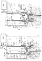
- FIGs. 1 and 2 we see the internal tank 1 of a nuclear reactor with fast neutrons formed by cylindrical ferrules with vertical axis such as 1a and by a frustoconical step 2, delimiting inside the reactor tank, a hot collector 4 and a cold collector 5.
- the cylindrical ferrules of the internal tank 1 are either ferrules having the axis Z-Z 'of the tank as their axis (FIG. 1), or ferrules for the passage of the intermediate exchangers and of the pumps through the step 2.
- the internal tank is shown in Figs. 1 and 2 in the form of a single wall, to avoid complicating the description, but this tank is generally of a more complex structure; this structure is however equivalent in its function of separation of the hot collector and the cold collector, to a single wall as shown.
- the part of the step 2 shown in FIGS. 1 and 2 is frustoconical in shape and extends in the radial direction of the main reactor vessel, the axis of symmetry of revolution Z-Z 'in FIG. 1.
- the hot manifold 4, located above the step 2 is at a level generally higher than the level of the cold manifold 5 located below the step 2.
- the shape and structure of the step ensures communication between the hot manifold 4 with the outlet of the core, that is to say with its upper part in which the assembly heads are located.
- the hot collector 4 thus collects the sodium which has heated up in the core, by circulating from bottom to top in contact with the fuel assemblies.
- the upper level 4a of hot sodium in the collector 4 has been shown, this level being substantially constant when the operating parameters of the reactor themselves remain constant. This level is however a dynamic level which is established during the circulation of sodium which will be described below.
- the cold collector 5 is in communication with the lower part of the core corresponding to the feet of the assemblies into which the cooled sodium is injected, the level of which is established in 5a during the operation of the reactor.
- the intermediate exchangers and the reactor pumps constituting the elements of the normal cooling circuit of the reactor pass through the step 2, by means of feed-through devices making it possible to separate the hot sodium from the collector 4, from the cooled sodium from the collector 5.
- the exchangers of intermediate heat have inlet vents at their upper part in the hot collector, and outlet vents at their lower part, in the cold collector.
- the hot sodium in the collector 4 enters the intermediate exchangers in which it is cooled by secondary sodium, the heat taken by this secondary sodium being used to vaporize water in the steam generators located outside the tank of the reactor.
- the sodium cooled at the outlet of the intermediate exchangers is collected in the cold collector 5 and injected, thanks to the pumps, into the lower part of the core. This cooled sodium crosses the heart from bottom to top while heating, before returning to the hot collector 4.
- an emergency exchanger 7 is seen immersed in the sodium of the hot collector 4 comprising sodium inlet openings 9 in its upper part and sodium outlet openings 10 in its lower part.
- a back-up exchanger such as the exchanger 7 is well known in the prior art and comprises, inside its outer casing immersed in the liquid sodium of the tank, a bundle of tubes traversed internally by liquid sodium, making it possible to take the heat from the primary liquid sodium entering the shell of the exchanger 7 through the openings 9. The primary sodium emerging through the openings 10, when the heat exchanger 7 is in operation, has therefore been cooled.
- the liquid sodium passing through the tubes of the heat exchanger bundle 7 is in turn cooled, outside the tank, in a sodium-air exchanger, the whole of the heat exchanger 7, of the sodium exchanger -air and their connection piping constituting a cooling device according to the prior art.
- This cooling device is used when the nuclear reactor is stopped, to take the residual heat from this reactor.
- the step 2 is pierced with an opening 11 centered on the axis 8 of the exchanger 7.
- a cylindrical shell 12 whose diameter is greater than the diameter of the exchanger 7 is fixed to the step 2, by welding, along the contour of the opening 11.
- This ferrule penetrates over a certain height inside the cold manifold 5, an annular bottom 13 being fixed by welding at its lower end.
- a vertical tubular conduit 14 is fixed along the central opening of the bottom 13 centered on the axis 8 of the exchanger 7.
- the tubular conduit 14 is coaxial with the casing of the exchanger 7.
- the lower end of the vertical duct 14 is located in the cold manifold 5 and the upper end of this duct, in the hot manifold 4, a little below the lower end of the shell of the exchanger 7.
- a bell 16 open towards the bottom is fixed to the lower end of the shell of the exchanger 7, in the vertical extension of this shell.
- the bell 16 When the exchanger 7 is in place in the reactor vessel, the bell 16 covers the upper end of the tube 14; this bell 16 having a cross section of dimension greater than that of the duct 14 provides a free space all around the upper end of the duct 14.
- the upper end of the duct 14 therefore opens, inside the hot manifold 4, under the bell 16, at a certain axial distance below its upper internal surface.
- the bell 16 is connected by a tube 17 fixed along the casing of the exchanger 7, to a pressurized argon tank 18 disposed outside the vessel of the nuclear reactor.
- the reservoir 18 is equipped with a stop valve or tap 20 making it possible to send argon into the pipeline 17 and into the bell 16 or to isolate the pipeline and the bell with respect to the reservoir 18.
- a tube d the exhaust 21 connected to the low pressure effluent circuit is also arranged as a bypass on the tube 17, upstream of the reservoir 18, this exhaust tube 21 being fitted with a valve 22.
- a ferrule 25 On the shell of the exchanger 7 is fixed, at a level higher than the level of the cooled sodium outlet openings 10, a ferrule 25 whose upper end surrounds the lower part of the shell of the exchanger 7 and whose lower end of smaller diameter than the upper part enters the space provided by the ferrule 12.
- the ferrule 25 has, in its lower part, a diameter which is only slightly less than the diameter of the ferrule 12 leaving a small clearance between the ferrules 12 and 25.
- Fig. 1 the cooling device has been shown in a normal operating phase of the reactor, the backup heat exchanger 7 being stopped.
- the bell 16 and the vertical tubular conduit 14 contain argon under pressure coming from the reservoir 18. This argon is at a pressure sufficient to maintain a level of hot liquid sodium 4'a in the bell 16 and a level of cooled liquid sodium 5 ′ a in the tube 14.
- the argon thus constitutes, in the upper part of the conduit 14 and in the bell 16, a gas cap totally insulating the hot sodium contained in the collector 4 of the cooled sodium contained in the collector 5.
- the circulation of liquid sodium in the vessel of the nuclear reactor is then identical to the circulation of sodium in a vessel whose step is not crossed by a conduit such as conduit 14.
- the argon previously contained in the duct 14 and the bell 16 is evacuated, the duct and the bell then being filled with liquid metal.
- the exhaust tube 21 is connected with the low pressure effluent circuit, the valve 20 being closed. This ensures the communication of the hot collector 4 with the cold collector 5, via the bell 16 and the conduit 14.
- the cooled sodium leaving the exchanger 7 through the openings 10 is then sent directly to the collector cold, via the bell 16 and the conduit 14 (arrows 27).
- the cooled sodium is channeled by the shell 25 which makes it possible to avoid bringing the cooled sodium into contact in the exchanger 7 with the step 2, contacting which would cause sudden thermal shocks.
- the cooled sodium is sent directly to the cold collector, without having to pass through the intermediate exchangers.
- This cooled sodium collected in the cold collector is sent to the lower part of the heart, through the heart from bottom to top while heating and returns to the hot collector.
- the liquid metal of the collector 4 enters the exchanger 7 through the openings 9 (arrows 29).
- the primary sodium circuit during emergency cooling is therefore very simple, constituting a single loop with a hot part comprising the core and the hot collector and a cold part comprising the cold collector. It can therefore operate in natural convection. This results in very good efficiency and very good efficiency of the cooling device.
- the temperatures in the manifolds are more uniform, which reduces local thermal thermal stresses.
- a cooling device may comprise several emergency exchangers each associated with a duct crossing the step and a vaning bell to cap the duct.
- the invention applies to any nuclear reactor with fast neutrons of the integrated type, whatever the shape of the step of its internal vessel.
Claims (6)
Applications Claiming Priority (2)
| Application Number | Priority Date | Filing Date | Title |
|---|---|---|---|
| FR8611892A FR2603131B1 (fr) | 1986-08-20 | 1986-08-20 | Dispositif de refroidissement de secours d'un reacteur nucleaire a neutrons rapides |
| FR8611892 | 1986-08-20 |
Publications (2)
| Publication Number | Publication Date |
|---|---|
| EP0258131A1 EP0258131A1 (de) | 1988-03-02 |
| EP0258131B1 true EP0258131B1 (de) | 1991-01-16 |
Family
ID=9338403
Family Applications (1)
| Application Number | Title | Priority Date | Filing Date |
|---|---|---|---|
| EP87401865A Expired - Lifetime EP0258131B1 (de) | 1986-08-20 | 1987-08-10 | Notkühleinrichtung für schnellen Neutronenreaktor |
Country Status (5)
| Country | Link |
|---|---|
| US (1) | US4832904A (de) |
| EP (1) | EP0258131B1 (de) |
| JP (1) | JPS63113394A (de) |
| DE (1) | DE3767411D1 (de) |
| FR (1) | FR2603131B1 (de) |
Families Citing this family (6)
| Publication number | Priority date | Publication date | Assignee | Title |
|---|---|---|---|---|
| GB8827395D0 (en) * | 1988-11-23 | 1988-12-29 | Nat Nuclear Corp Ltd | Fast nuclear reactor |
| FR2681977B1 (fr) * | 1991-09-30 | 1993-12-31 | Framatome | Dispositif de refroidissement adaptable sur un telemanipulateur et son utilisation pour une intervention dans un milieu hostile a temperature elevee. |
| US5491731A (en) * | 1994-07-05 | 1996-02-13 | Westinghouse Electric Corporation | Method and system for maintaining pressure in a nuclear power plant primary loop during startup or shutdown |
| JP3597165B2 (ja) * | 2001-11-16 | 2004-12-02 | 核燃料サイクル開発機構 | 原子炉容器の熱荷重緩和装置 |
| KR100597722B1 (ko) * | 2004-01-02 | 2006-07-10 | 한국원자력연구소 | 액체금속로의 안정적인 피동 잔열제거 계통 |
| CN110111912B (zh) * | 2019-06-14 | 2020-09-29 | 北京卫星环境工程研究所 | 自蒸发金属磁流体一体化反应堆 |
Family Cites Families (4)
| Publication number | Priority date | Publication date | Assignee | Title |
|---|---|---|---|---|
| FR2357987A1 (fr) * | 1976-07-06 | 1978-02-03 | Commissariat Energie Atomique | Reacteur nucleaire a neutrons rapides |
| US4367194A (en) * | 1980-09-22 | 1983-01-04 | The United States Of America As Represented By The United States Department Of Energy | Emergency core cooling system |
| FR2506498B1 (fr) * | 1981-05-22 | 1986-03-07 | Commissariat Energie Atomique | Reacteur nucleaire a neutrons rapides muni de dispositifs d'evacuation de la puissance residuelle |
| FR2555794B1 (fr) * | 1983-11-25 | 1986-03-28 | Commissariat Energie Atomique | Reacteur nucleaire a neutrons rapides equipe de moyens de refroidissement de secours |
-
1986
- 1986-08-20 FR FR8611892A patent/FR2603131B1/fr not_active Expired - Fee Related
-
1987
- 1987-08-10 DE DE8787401865T patent/DE3767411D1/de not_active Expired - Fee Related
- 1987-08-10 EP EP87401865A patent/EP0258131B1/de not_active Expired - Lifetime
- 1987-08-20 US US07/087,287 patent/US4832904A/en not_active Expired - Fee Related
- 1987-08-20 JP JP62207340A patent/JPS63113394A/ja active Pending
Also Published As
| Publication number | Publication date |
|---|---|
| DE3767411D1 (de) | 1991-02-21 |
| US4832904A (en) | 1989-05-23 |
| EP0258131A1 (de) | 1988-03-02 |
| FR2603131B1 (fr) | 1990-12-07 |
| JPS63113394A (ja) | 1988-05-18 |
| FR2603131A1 (fr) | 1988-02-26 |
Similar Documents
| Publication | Publication Date | Title |
|---|---|---|
| EP0004218B1 (de) | Schneller Kernreaktor mit mindestens einem Hilfs-Wärmetauscher | |
| EP0022714B1 (de) | Mit einem Flüssigmetall gekühlter schnelle Neutronen-Kernreaktor mit einem System zum Abführen der Restwärme | |
| EP0246969B1 (de) | Kleiner Druckwasserkernreaktor mit Naturumlauf | |
| EP0068913B1 (de) | Schneller Brüter mit Einrichtung zur Abführung von Restwärme | |
| EP0258131B1 (de) | Notkühleinrichtung für schnellen Neutronenreaktor | |
| EP0006802B1 (de) | Mit flüssigem Metall gekühlter schneller Kernreaktor | |
| EP0238390B1 (de) | Innere Struktur eines Kernreaktors mit länglichem Druckbehälter | |
| EP0163564B1 (de) | Schneller Neutronenkernreaktor mit Dampferzeuger, integriert im Behälter | |
| EP0055643A1 (de) | Kernreaktor, der von einem flüssigen Metall gekühlt wird, das in einem oben angeordnete Verschlüsse aufweisenden Behälter enthalten ist | |
| EP0153225B1 (de) | Wärmetauscher mit einem Notkühlsystem und schneller Kernreaktor mit einem derartigen Wärmetauscher | |
| EP0006800B1 (de) | Mit flüssigem Metall gekühlter schneller Kernreaktor | |
| EP0055963B1 (de) | Flüssigmetallgekühlter Kernreaktor mit einem am Boden gekühlten Behälter | |
| EP0083545B1 (de) | Sicherheitsvorrichtung zur Ableitung der entstehenden Wärme beim Abschalten eines schnellen Brüters | |
| EP0105781B1 (de) | Sekundärer Kühlkreislauf für einen Flüssigmetall-gekühlten Kernreaktor und Dampferzeuger angepasst an einen solchen Kreislauf | |
| EP0018262B1 (de) | Schneller Kernreaktor mit einem zylindrischen Innenbehälter | |
| EP0048672B1 (de) | Atomkernreaktor mit Wärmetauschern in integrierter Bauweise | |
| EP0064920B1 (de) | Vorrichtung zur Dampferzeugung und zur Ableitung von Wärme in einem schnellen Brüter | |
| WO1998001864A1 (fr) | Reacteur nucleaire comportant une cuve dans laquelle est dispose le coeur du reacteur et procede de refroidissement du coeur du reacteur a l'arret | |
| EP0091872B1 (de) | Kollektor und Scheidungsanordnung für Flüssigmetall- Kühlmittel in einem schnellen Kernreaktor | |
| EP0086695B1 (de) | Dampferzeuger mit U-Rohrbündel und Überhitzer | |
| FR2555794A1 (fr) | Reacteur nucleaire a neutrons rapides equipe de moyens de refroidissement de secours | |
| EP0047698B1 (de) | Kernreaktor mit Kreislauf der Primärkühlflüssigkeit, beruhend auf gemischter Konvektion | |
| FR2533354A1 (fr) | Circuit caloporteur secondaire pour un reacteur nucleaire a metal liquide | |
| EP0216667B1 (de) | Rückhaltevorrichtung für eine Flüssigkeit um zu verhindern, dass eine offene, im wesentlichen horizontale Leitung beim Unterschreiten einer bestimmten Zuflussmenge leer läuft | |
| FR2544053A1 (fr) | Generateur de vapeur pour reacteur refroidi par un metal liquide |
Legal Events
| Date | Code | Title | Description |
|---|---|---|---|
| PUAI | Public reference made under article 153(3) epc to a published international application that has entered the european phase |
Free format text: ORIGINAL CODE: 0009012 |
|
| 17P | Request for examination filed |
Effective date: 19871218 |
|
| AK | Designated contracting states |
Kind code of ref document: A1 Designated state(s): DE GB IT NL |
|
| 17Q | First examination report despatched |
Effective date: 19891129 |
|
| RAP1 | Party data changed (applicant data changed or rights of an application transferred) |
Owner name: FRAMATOME |
|
| GRAA | (expected) grant |
Free format text: ORIGINAL CODE: 0009210 |
|
| AK | Designated contracting states |
Kind code of ref document: B1 Designated state(s): DE GB IT NL |
|
| ITF | It: translation for a ep patent filed |
Owner name: JACOBACCI & PERANI S.P.A. |
|
| REF | Corresponds to: |
Ref document number: 3767411 Country of ref document: DE Date of ref document: 19910221 |
|
| GBT | Gb: translation of ep patent filed (gb section 77(6)(a)/1977) | ||
| PGFP | Annual fee paid to national office [announced via postgrant information from national office to epo] |
Ref country code: DE Payment date: 19910717 Year of fee payment: 5 |
|
| PGFP | Annual fee paid to national office [announced via postgrant information from national office to epo] |
Ref country code: GB Payment date: 19910802 Year of fee payment: 5 |
|
| PGFP | Annual fee paid to national office [announced via postgrant information from national office to epo] |
Ref country code: NL Payment date: 19910831 Year of fee payment: 5 |
|
| PLBE | No opposition filed within time limit |
Free format text: ORIGINAL CODE: 0009261 |
|
| STAA | Information on the status of an ep patent application or granted ep patent |
Free format text: STATUS: NO OPPOSITION FILED WITHIN TIME LIMIT |
|
| 26N | No opposition filed | ||
| PG25 | Lapsed in a contracting state [announced via postgrant information from national office to epo] |
Ref country code: GB Effective date: 19920810 |
|
| PG25 | Lapsed in a contracting state [announced via postgrant information from national office to epo] |
Ref country code: NL Effective date: 19930301 |
|
| GBPC | Gb: european patent ceased through non-payment of renewal fee |
Effective date: 19920810 |
|
| NLV4 | Nl: lapsed or anulled due to non-payment of the annual fee | ||
| PG25 | Lapsed in a contracting state [announced via postgrant information from national office to epo] |
Ref country code: DE Effective date: 19930501 |
|
| PG25 | Lapsed in a contracting state [announced via postgrant information from national office to epo] |
Ref country code: IT Free format text: LAPSE BECAUSE OF NON-PAYMENT OF DUE FEES;WARNING: LAPSES OF ITALIAN PATENTS WITH EFFECTIVE DATE BEFORE 2007 MAY HAVE OCCURRED AT ANY TIME BEFORE 2007. THE CORRECT EFFECTIVE DATE MAY BE DIFFERENT FROM THE ONE RECORDED. Effective date: 20050810 |