EP0258131B1 - Emergency cooling arrangement for fast neutron reactor - Google Patents
Emergency cooling arrangement for fast neutron reactor Download PDFInfo
- Publication number
- EP0258131B1 EP0258131B1 EP87401865A EP87401865A EP0258131B1 EP 0258131 B1 EP0258131 B1 EP 0258131B1 EP 87401865 A EP87401865 A EP 87401865A EP 87401865 A EP87401865 A EP 87401865A EP 0258131 B1 EP0258131 B1 EP 0258131B1
- Authority
- EP
- European Patent Office
- Prior art keywords
- liquid metal
- reactor
- collar
- bell
- cooling device
- Prior art date
- Legal status (The legal status is an assumption and is not a legal conclusion. Google has not performed a legal analysis and makes no representation as to the accuracy of the status listed.)
- Expired - Lifetime
Links
Images
Classifications
-
- G—PHYSICS
- G21—NUCLEAR PHYSICS; NUCLEAR ENGINEERING
- G21C—NUCLEAR REACTORS
- G21C15/00—Cooling arrangements within the pressure vessel containing the core; Selection of specific coolants
- G21C15/18—Emergency cooling arrangements; Removing shut-down heat
-
- Y—GENERAL TAGGING OF NEW TECHNOLOGICAL DEVELOPMENTS; GENERAL TAGGING OF CROSS-SECTIONAL TECHNOLOGIES SPANNING OVER SEVERAL SECTIONS OF THE IPC; TECHNICAL SUBJECTS COVERED BY FORMER USPC CROSS-REFERENCE ART COLLECTIONS [XRACs] AND DIGESTS
- Y02—TECHNOLOGIES OR APPLICATIONS FOR MITIGATION OR ADAPTATION AGAINST CLIMATE CHANGE
- Y02E—REDUCTION OF GREENHOUSE GAS [GHG] EMISSIONS, RELATED TO ENERGY GENERATION, TRANSMISSION OR DISTRIBUTION
- Y02E30/00—Energy generation of nuclear origin
- Y02E30/30—Nuclear fission reactors
Definitions
- the invention relates to an emergency cooling device for an integrated type fast neutron nuclear reactor.
- Integrated type fast neutron nuclear reactors comprise a main tank containing liquid metal, such as sodium, constituting the cooling fluid of the nuclear reactor in which the core of the reactor made up of fuel assemblies is immersed.
- the main reactor vessel is internally divided into two zones, by a complex structure constituting the internal reactor vessel. This complex structure is equivalent to a wall, a part of which called a step, extends radially with respect to the main tank.
- the two zones delimited by the internal tank are arranged, for one, essentially at the top of the tank, and for the other, at the bottom.
- the upper zone called the hot collector
- the lower zone called the cold collector
- emergency heat exchangers immersed in the reactor vessel are used, inside the hot collector.
- These emergency heat exchangers in which the sodium coolant of the reactor circulates are associated with heat exchangers of the sodium-air type, arranged outside the reactor vessel and ensuring the cooling of secondary liquid sodium which s 'is heated by thermal contact with the primary sodium cooling the reactor through the exchanger immersed in the tank.
- These emergency exchangers, associated with sodium-air exchangers constitute circuits completely independent of the main circuits.
- the emergency exchangers which plunge directly into the hot collector of the tank, have inlet openings for sodium to be cooled at their upper part and outlet openings for cooled sodium at their lower part.
- the cooled sodium is therefore reintroduced into the hot collector and must take a complicated route to pass through the cold collector and, from there, return to the bottom or bottom of the fuel assemblies.
- This complex route includes the pump passages and the bodies of the intermediate exchangers of the main power evacuation circuits. This results in fairly large pressure drops, lower efficiency of the emergency cooling device of the reactor and significant temperature dissymmetries in the hot manifold causing additional thermal stresses on the step.
- FR-A-2,555,794 discloses an emergency cooling device comprising an auxiliary heat exchanger suspended from the reactor slab and passing through the internal vessel, so that the upper part of the exchanger comprising openings inlet of the reactor coolant metal is located inside the internal tank, in the hot liquid metal.
- the lower part of the exchanger through which the liquid metal cooled in the exchanger exits is connected by a pipe to the supply base of the core.
- a valve arranged in the pipe and normally closed under the effect of the pressure in the bed base opens under the effect of a pressure drop due to the stopping of the primary pumps, so as to put the backup heat exchanger in service.
- Such a device comprising a movable member inside a conduit immersed in the liquid metal coolant of the reactor is not very safe to operate and cannot be easily checked or repaired.
- the object of the invention is therefore to propose an integrated type fast neutron nuclear reactor having a main tank containing liquid metal in which the reactor core is immersed and comprising a wall separating the internal volume of the tank in an upper zone receiving the hot liquid metal having passed through the reactor core, called the hot collector, and a lower zone receiving the cooled liquid metal, called the cold collector, this wall comprising a part extending in the radial direction of the tank called the redan, the reaction being provided with an emergency cooling device comprising at least one heat exchanger immersed in the hot collector and having outlet openings of liquid metal cooled at its lower part and a ferrule fixed to the casing of the heat exchanger , above the liquid metal outlet openings, device which is highly efficient and simple to use and which can be operated remotely.
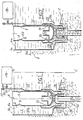
- FIGs. 1 and 2 we see the internal tank 1 of a nuclear reactor with fast neutrons formed by cylindrical ferrules with vertical axis such as 1a and by a frustoconical step 2, delimiting inside the reactor tank, a hot collector 4 and a cold collector 5.
- the cylindrical ferrules of the internal tank 1 are either ferrules having the axis Z-Z 'of the tank as their axis (FIG. 1), or ferrules for the passage of the intermediate exchangers and of the pumps through the step 2.
- the internal tank is shown in Figs. 1 and 2 in the form of a single wall, to avoid complicating the description, but this tank is generally of a more complex structure; this structure is however equivalent in its function of separation of the hot collector and the cold collector, to a single wall as shown.
- the part of the step 2 shown in FIGS. 1 and 2 is frustoconical in shape and extends in the radial direction of the main reactor vessel, the axis of symmetry of revolution Z-Z 'in FIG. 1.
- the hot manifold 4, located above the step 2 is at a level generally higher than the level of the cold manifold 5 located below the step 2.
- the shape and structure of the step ensures communication between the hot manifold 4 with the outlet of the core, that is to say with its upper part in which the assembly heads are located.
- the hot collector 4 thus collects the sodium which has heated up in the core, by circulating from bottom to top in contact with the fuel assemblies.
- the upper level 4a of hot sodium in the collector 4 has been shown, this level being substantially constant when the operating parameters of the reactor themselves remain constant. This level is however a dynamic level which is established during the circulation of sodium which will be described below.
- the cold collector 5 is in communication with the lower part of the core corresponding to the feet of the assemblies into which the cooled sodium is injected, the level of which is established in 5a during the operation of the reactor.
- the intermediate exchangers and the reactor pumps constituting the elements of the normal cooling circuit of the reactor pass through the step 2, by means of feed-through devices making it possible to separate the hot sodium from the collector 4, from the cooled sodium from the collector 5.
- the exchangers of intermediate heat have inlet vents at their upper part in the hot collector, and outlet vents at their lower part, in the cold collector.
- the hot sodium in the collector 4 enters the intermediate exchangers in which it is cooled by secondary sodium, the heat taken by this secondary sodium being used to vaporize water in the steam generators located outside the tank of the reactor.
- the sodium cooled at the outlet of the intermediate exchangers is collected in the cold collector 5 and injected, thanks to the pumps, into the lower part of the core. This cooled sodium crosses the heart from bottom to top while heating, before returning to the hot collector 4.
- an emergency exchanger 7 is seen immersed in the sodium of the hot collector 4 comprising sodium inlet openings 9 in its upper part and sodium outlet openings 10 in its lower part.
- a back-up exchanger such as the exchanger 7 is well known in the prior art and comprises, inside its outer casing immersed in the liquid sodium of the tank, a bundle of tubes traversed internally by liquid sodium, making it possible to take the heat from the primary liquid sodium entering the shell of the exchanger 7 through the openings 9. The primary sodium emerging through the openings 10, when the heat exchanger 7 is in operation, has therefore been cooled.
- the liquid sodium passing through the tubes of the heat exchanger bundle 7 is in turn cooled, outside the tank, in a sodium-air exchanger, the whole of the heat exchanger 7, of the sodium exchanger -air and their connection piping constituting a cooling device according to the prior art.
- This cooling device is used when the nuclear reactor is stopped, to take the residual heat from this reactor.
- the step 2 is pierced with an opening 11 centered on the axis 8 of the exchanger 7.
- a cylindrical shell 12 whose diameter is greater than the diameter of the exchanger 7 is fixed to the step 2, by welding, along the contour of the opening 11.
- This ferrule penetrates over a certain height inside the cold manifold 5, an annular bottom 13 being fixed by welding at its lower end.
- a vertical tubular conduit 14 is fixed along the central opening of the bottom 13 centered on the axis 8 of the exchanger 7.
- the tubular conduit 14 is coaxial with the casing of the exchanger 7.
- the lower end of the vertical duct 14 is located in the cold manifold 5 and the upper end of this duct, in the hot manifold 4, a little below the lower end of the shell of the exchanger 7.
- a bell 16 open towards the bottom is fixed to the lower end of the shell of the exchanger 7, in the vertical extension of this shell.
- the bell 16 When the exchanger 7 is in place in the reactor vessel, the bell 16 covers the upper end of the tube 14; this bell 16 having a cross section of dimension greater than that of the duct 14 provides a free space all around the upper end of the duct 14.
- the upper end of the duct 14 therefore opens, inside the hot manifold 4, under the bell 16, at a certain axial distance below its upper internal surface.
- the bell 16 is connected by a tube 17 fixed along the casing of the exchanger 7, to a pressurized argon tank 18 disposed outside the vessel of the nuclear reactor.
- the reservoir 18 is equipped with a stop valve or tap 20 making it possible to send argon into the pipeline 17 and into the bell 16 or to isolate the pipeline and the bell with respect to the reservoir 18.
- a tube d the exhaust 21 connected to the low pressure effluent circuit is also arranged as a bypass on the tube 17, upstream of the reservoir 18, this exhaust tube 21 being fitted with a valve 22.
- a ferrule 25 On the shell of the exchanger 7 is fixed, at a level higher than the level of the cooled sodium outlet openings 10, a ferrule 25 whose upper end surrounds the lower part of the shell of the exchanger 7 and whose lower end of smaller diameter than the upper part enters the space provided by the ferrule 12.
- the ferrule 25 has, in its lower part, a diameter which is only slightly less than the diameter of the ferrule 12 leaving a small clearance between the ferrules 12 and 25.
- Fig. 1 the cooling device has been shown in a normal operating phase of the reactor, the backup heat exchanger 7 being stopped.
- the bell 16 and the vertical tubular conduit 14 contain argon under pressure coming from the reservoir 18. This argon is at a pressure sufficient to maintain a level of hot liquid sodium 4'a in the bell 16 and a level of cooled liquid sodium 5 ′ a in the tube 14.
- the argon thus constitutes, in the upper part of the conduit 14 and in the bell 16, a gas cap totally insulating the hot sodium contained in the collector 4 of the cooled sodium contained in the collector 5.
- the circulation of liquid sodium in the vessel of the nuclear reactor is then identical to the circulation of sodium in a vessel whose step is not crossed by a conduit such as conduit 14.
- the argon previously contained in the duct 14 and the bell 16 is evacuated, the duct and the bell then being filled with liquid metal.
- the exhaust tube 21 is connected with the low pressure effluent circuit, the valve 20 being closed. This ensures the communication of the hot collector 4 with the cold collector 5, via the bell 16 and the conduit 14.
- the cooled sodium leaving the exchanger 7 through the openings 10 is then sent directly to the collector cold, via the bell 16 and the conduit 14 (arrows 27).
- the cooled sodium is channeled by the shell 25 which makes it possible to avoid bringing the cooled sodium into contact in the exchanger 7 with the step 2, contacting which would cause sudden thermal shocks.
- the cooled sodium is sent directly to the cold collector, without having to pass through the intermediate exchangers.
- This cooled sodium collected in the cold collector is sent to the lower part of the heart, through the heart from bottom to top while heating and returns to the hot collector.
- the liquid metal of the collector 4 enters the exchanger 7 through the openings 9 (arrows 29).
- the primary sodium circuit during emergency cooling is therefore very simple, constituting a single loop with a hot part comprising the core and the hot collector and a cold part comprising the cold collector. It can therefore operate in natural convection. This results in very good efficiency and very good efficiency of the cooling device.
- the temperatures in the manifolds are more uniform, which reduces local thermal thermal stresses.
- a cooling device may comprise several emergency exchangers each associated with a duct crossing the step and a vaning bell to cap the duct.
- the invention applies to any nuclear reactor with fast neutrons of the integrated type, whatever the shape of the step of its internal vessel.
Description
L'invention concerne un dispositif de refroidissement de secours d'un réacteur nucléaire à neutrons rapides de type intégré.The invention relates to an emergency cooling device for an integrated type fast neutron nuclear reactor.
Les réacteurs nucléaires à neutrons rapides de type intégré comportent une cuve principale contenant du métal liquide, tel que du sodium, constituant le fluide de refroidissement du réacteur nucléaire dans lequel est plongé le coeur du réacteur constitué par des assemblages combustibles. La cuve principale du réacteur est partagée intérieurement en deux zones, par une structure complexe constituant la cuve interne du réacteur. Cette structure complexe est équivalente à une paroi dont une partie appelée redan, s'étend radialement par rapport à la cuve principale.Integrated type fast neutron nuclear reactors comprise a main tank containing liquid metal, such as sodium, constituting the cooling fluid of the nuclear reactor in which the core of the reactor made up of fuel assemblies is immersed. The main reactor vessel is internally divided into two zones, by a complex structure constituting the internal reactor vessel. This complex structure is equivalent to a wall, a part of which called a step, extends radially with respect to the main tank.
Les deux zones délimitées par la cuve interne sont disposées, pour l'une, essentiellement à la partie supérieure de la cuve, et pour l'autre, à la partie inférieure. La zone supérieure, appelée collecteur chaud, communique avec la sortie du coeur et reçoit le métal liquide chaud ayant traversé les assemblages combustibles du coeur. La zone inférieure, appelée collecteur froid, reçoit le sodium refroidi dans les échangeurs intermédiaires plongés dans la cuve principale du réacteur. Ce métal liquide refroidi est ensuite renvoyé, à partir du collecteur froid, à la partie inférieure des assemblages du coeur.The two zones delimited by the internal tank are arranged, for one, essentially at the top of the tank, and for the other, at the bottom. The upper zone, called the hot collector, communicates with the outlet of the heart and receives the hot liquid metal having passed through the fuel assemblies of the heart. The lower zone, called the cold collector, receives the cooled sodium in the intermediate exchangers immersed in the main tank of the reactor. This cooled liquid metal is then returned, from the cold collector, to the lower part of the core assemblies.
Lorsqu'un réacteur nucléaire a fonctionné pendant un certain temps, il continue à dégager une puissance résiduelle non négligeable, lorsqu'il est mis à l'arrêt, c'est-à-dire lorsqu'on introduit les barres de commande du réacteur, à l'intérieur du coeur, dans leur position d'insertion maximale. Il est donc nécessaire d'évacuer la puissance résiduelle du réacteur pour ne pas endommager les composants et structures internes, par un élévation de température excessive.When a nuclear reactor has been operating for a certain time, it continues to generate a significant residual power when it is shut down, that is to say when the control rods of the reactor are introduced, inside the heart, in their maximum insertion position. It is therefore necessary to drain the residual power from the reactor in order not to damage the internal components and structures, by an excessive temperature rise.
Cette possibilité d'évacuer la puissance résiduelle du réacteur doit être maintenue, même si le réacteur a subi des avaries importantes et si les circuits principaux d'évacuation de puissance qui sont mis en oeuvre pendant la marche normale du réacteur sont hors d'état de fonctionner.This possibility of discharging the residual power from the reactor must be maintained, even if the reactor has suffered significant damage and if the main power evacuation circuits which are implemented during normal operation of the reactor are out of order. function.
On fait donc appel à des circuits de secours qui ne sont utilisés que lorsque le réacteur est à l'arrêt et lorsque les circuits principaux sont hors d'état de fonctionner.Emergency circuits are therefore used which are used only when the reactor is stopped and when the main circuits are out of order.
Dans le cas des réacteurs nucléaires à neutrons rapides refroidis par du sodium liquide et de type intégré, on utilise des échangeurs de chaleur de secours plongés dans la cuve du réacteur, à l'intérieur du collecteur chaud. Ces échangeurs de chaleur de secours dans lesquels circule le sodium liquide de refroidissement du réacteur, sont associés à des échangeurs de chaleur du type sodium-air, disposés à l'extérieur de la cuve du réacteur et assurant le refroidissement de sodium liquide secondaire qui s'est échauffé, par mise en contact thermique avec le sodium primaire de refroidissement du réacteur traversant l'échangeur plongé dans la cuve. Ces échangeurs de secours, associés à des échangeurs sodium-air, constituent des circuits totalement indépendant des circuits principaux.In the case of fast neutron nuclear reactors cooled by liquid sodium and of the integrated type, emergency heat exchangers immersed in the reactor vessel are used, inside the hot collector. These emergency heat exchangers in which the sodium coolant of the reactor circulates, are associated with heat exchangers of the sodium-air type, arranged outside the reactor vessel and ensuring the cooling of secondary liquid sodium which s 'is heated by thermal contact with the primary sodium cooling the reactor through the exchanger immersed in the tank. These emergency exchangers, associated with sodium-air exchangers, constitute circuits completely independent of the main circuits.
Les échangeurs de secours, qui plongent directement dans le collecteur chaud de la cuve, comportent des ouvertures d'entrée du sodium à refroidir à leur partie supérieure et des ouvertures de sortie de sodium refroidi, dans leur partie inférieure. Le sodium refroidi est donc réintroduit dans le collecteur chaud et doit emprunter un parcours compliqué pour passer dans le collecteur froid et, de là, revenir à la partie inférieure ou pied des assemblages combustibles. Ce parcours complexe comporte les passages de pompes et les corps des échangeurs intermédiaires des circuits principaux d'évacuation de puissance. Il en résulte des pertes de charge assez importantes, une efficacité moindre du dispositif de refroidissement de secours du réacteur et des dissymétries de température importantes dans le collecteur chaud entraînant des contraintes thermiques supplémentaires sur le redan.The emergency exchangers, which plunge directly into the hot collector of the tank, have inlet openings for sodium to be cooled at their upper part and outlet openings for cooled sodium at their lower part. The cooled sodium is therefore reintroduced into the hot collector and must take a complicated route to pass through the cold collector and, from there, return to the bottom or bottom of the fuel assemblies. This complex route includes the pump passages and the bodies of the intermediate exchangers of the main power evacuation circuits. This results in fairly large pressure drops, lower efficiency of the emergency cooling device of the reactor and significant temperature dissymmetries in the hot manifold causing additional thermal stresses on the step.
On connaît, par le FR-A-2.555.794, un dispositif de refroidissement de secours comportant un échangeur de chaleur auxiliaire suspendu à la dalle du réacteur et traversant la cuve interne, de manière que la partie supérieure de l'échangeur comprenant des ouvertures d'entrée du métal liquide de refroidissement du réacteur soit située à l'intérieur de la cuve interne, dans le métal liquide chaud. La partie inférieure de l'échangeur par laquelle sort le métal liquide refroidi dans l'échangeur est reliée par une conduite au sommier d'alimentation du coeur. Un clapet disposé dans la conduite et normalement fermé sous l'effet de la pression dans le sommier s'ouvre sous l'effet d'une chute de pression due à l'arrêt des pompes primaires, de manière à mettre l'échangeur de secours en service.FR-A-2,555,794 discloses an emergency cooling device comprising an auxiliary heat exchanger suspended from the reactor slab and passing through the internal vessel, so that the upper part of the exchanger comprising openings inlet of the reactor coolant metal is located inside the internal tank, in the hot liquid metal. The lower part of the exchanger through which the liquid metal cooled in the exchanger exits is connected by a pipe to the supply base of the core. A valve arranged in the pipe and normally closed under the effect of the pressure in the bed base opens under the effect of a pressure drop due to the stopping of the primary pumps, so as to put the backup heat exchanger in service.
Un tel dispositif comportant un organe mobile à l'intérieur d'un conduit plongé dans le metal liquide de refroidissement du réacteur n'est pas d'un fonctionnement très sûr et ne peut pas être facilement contrôlé ou réparé.Such a device comprising a movable member inside a conduit immersed in the liquid metal coolant of the reactor is not very safe to operate and cannot be easily checked or repaired.
De plus, on ne dispose pas de moyens de commande susceptibles d'actionner le clapet à distance.In addition, there are no control means capable of actuating the valve remotely.
Le but de l'invention est donc de proposer un réacteur nucléaire à neutrons rapides de type intégré ayant une cuve principale contenant du métal liquide dans lequel est plongé le coeur du réacteur et comportant une paroi séparant le volume interne de la cuve en une zone supérieure recevant le métal liquide chaud ayant traversé le coeur du réacteur, appelée collecteur chaud, et une zone inférieure recevant du métal liquide refroidi, appelée collecteur froid, cette paroi comportant une partie s'étendant dans la direction radiale de la cuve appelée redan, le réaction étant pourvu d'un dispositif de refroidissement de secours comportant au moins un échangeur de chaleur plongé dans le collecteur chaud et présentant des ouvertures de sortie de métal liquide refroidi à sa partie inférieure et une virole fixée sur l'enveloppe de l'échangeur de chaleur, au-dessus des ouvertures de sortie du métal liquide, dispositif qui soit d'une grande efficacité et d'une grande simplicité de mise en oeuvre et qui puisse être actionné à distance.The object of the invention is therefore to propose an integrated type fast neutron nuclear reactor having a main tank containing liquid metal in which the reactor core is immersed and comprising a wall separating the internal volume of the tank in an upper zone receiving the hot liquid metal having passed through the reactor core, called the hot collector, and a lower zone receiving the cooled liquid metal, called the cold collector, this wall comprising a part extending in the radial direction of the tank called the redan, the reaction being provided with an emergency cooling device comprising at least one heat exchanger immersed in the hot collector and having outlet openings of liquid metal cooled at its lower part and a ferrule fixed to the casing of the heat exchanger , above the liquid metal outlet openings, device which is highly efficient and simple to use and which can be operated remotely.
Dans ce but, le dispositif de refroidissement suivant l'invention comporte en outre:
- -un conduit tubulaire sensiblement vertical traversant le redan à la verticale de l'échangeur, dont l'extrémité inférieure débouche dans le collecteur froid et dont l'extrémité supérieure débouche dans le collecteur chaud, en-dessous de la partie inférieure de l'échangeur;
- -une cloche fixée sur l'échangeur de chaleur, dans le prolongement de sa partie inférieure, ouverte vers le bas et disposée de façon à coiffer la partie supérieure du conduit tout en ménageant un espace libre autour de cette partie supérieure, la virole étant prolongée vers le bas, de manière à entourer la cloche sur une partie au moins de sa hauteur et la partie supérieure du conduit tubulaire; et
- -des moyens de mise en pression de gaz neutre et de dépressurisation du volume intérieur de la cloche permettant de séparer complètement le métal liquide du collecteur chaud, du métal liquide du collecteur froid, par du gaz neutre sous pression, ou de mettre en communication la sortie du métal liquide refroidi de l'échangeur de chaleur, avec le collecteur froid, par l'intermédiaire de la cloche et du conduit.
- -a substantially vertical tubular conduit crossing the step vertically of the exchanger, the lower end of which opens into the cold collector and the upper end of which opens into the hot collector, below the lower part of the exchanger ;
- -a bell fixed on the heat exchanger, in the extension of its lower part, open downwards and arranged so as to cover the upper part of the duct while leaving a free space around this upper part, the shell being extended downwards, so as to surround the bell over at least part of its height and the upper part of the tubular conduit; and
- means for pressurizing neutral gas and depressurizing the interior volume of the bell, making it possible to completely separate the liquid metal from the hot collector, from the liquid metal from the cold collector, by pressurized neutral gas, or to put the communication outlet of the cooled liquid metal from the heat exchanger, with the cold collector, via the bell and the conduit.
Afin de bien faire comprendre l'invention, on va maintenant décrire, à titre d'exemple non limitatif, en se référent aux figures jointes en annexe, un mode de réalisation d'un dispositif de refroidissement selon l'invention, utilisé dans un réacteur nucléaire à neutrons rapides refroidi par du sodium liquide.
- -La Fig. 1 est une vue en élévation avec coupe partielle du dispositif de refroidissement en position dans la cuve du réacteur nucléaire, pendant le fonctionnement normal du réacteur.
- -La Fig. 2 est une vue en élévation avec coupe partielle du dispositif de refroidissement en position dans la cuve du réacteur nucléaire, pendant une phase d'arrêt du réacteur, avec mise en fonctionnement du refroidissement de secours.
- -Fig. 1 is an elevational view in partial section of the cooling device in position in the nuclear reactor vessel, during normal operation of the reactor.
- -Fig. 2 is an elevational view in partial section of the cooling device in position in the nuclear reactor vessel, during a shutdown phase of the reactor, with operation of the emergency cooling.
Sur les Fig. 1 et 2, on voit la cuve interne 1 d'un réacteur nucléaire à neutraons rapides constituée par des viroles cylindriques à axe vertical telles que 1a et par un redan tronconique 2, délimitant à l'intérieur de la cuve du réacteur, un collecteur chaud 4 et un collecteur froid 5.In Figs. 1 and 2, we see the internal tank 1 of a nuclear reactor with fast neutrons formed by cylindrical ferrules with vertical axis such as 1a and by a
Les viroles cylindriques de la cuve interne 1 sont soit des viroles ayant pour axe l'axe Z-Z' de la cuve (Fig. 1), soit des viroles de passage des échangeurs intermédiaires et des pompes à travers le redan 2.The cylindrical ferrules of the internal tank 1 are either ferrules having the axis Z-Z 'of the tank as their axis (FIG. 1), or ferrules for the passage of the intermediate exchangers and of the pumps through the
La cuve interne est représentée sur les Fig. 1 et 2 sous la forme d'une simple paroi, pour éviter de compliquer la description, mais cette cuve est généralement d'une structure plus complexe; cette structure est toutefois équivalente dans sa fonction de séparation du collecteur chaud et du collecteur froid, à une simple paroi telle que représentée.The internal tank is shown in Figs. 1 and 2 in the form of a single wall, to avoid complicating the description, but this tank is generally of a more complex structure; this structure is however equivalent in its function of separation of the hot collector and the cold collector, to a single wall as shown.
La partie du redan 2 représentée sur les Fig. 1 et 2 est de forme tronconique et s'étend dans la direction radiale de la cuve principale du réacteur dont on a représenté l'axe de symétrie de révolution Z-Z' sur la Fig. 1.The part of the
On voit que le collecteur chaud 4, situé au-dessus du redan 2 est à un niveau généralement supérieur au niveau du collecteur froid 5 situé au-dessous du redan 2. La forme et la structure du redan assurent une mise en communication du collecteur chaud 4 avec la sortie du coeur, c'est-à-dire avec sa partie supérieure dans laquelle se trouvent les têtes d'assemblage. Le collecteur chaud 4 recueille ainsi le sodium qui s'est échauffé dans le coeur, en circulant de bas en haut au contact des assemblages combustibles. On a représenté le niveau supérieur 4a du sodium chaud dans le collecteur 4, ce niveau étant sensiblement constant lorsque les paramètres de fonctionnement du réacteur restent eux-mêmes constants. Ce niveau est cependant un niveau dynamique qui s'établit lors de la circulation du sodium qui sera décrite ci-dessous.We see that the hot manifold 4, located above the
Le collecteur froid 5 est en communication avec la partie inférieure du coeur correspondant aux pieds des assemblages dans lesquels est injecté le sodium refroidi dont le niveau s'établit en 5a pendant le fonctionnement du réacteur.The
Les échangeurs intermédiaires et les pompes du réacteur constituant les éléments du circuit de refroidissement normal du réacteur traversent le redan 2, par l'intermédiaire de dispositifs de traversée permettant de séparer le sodium chaud du collecteur 4, du sodium refroidi du collecteur 5. Les échangeurs de chaleur intermédiaires comportent des ouies d'entrée à leur partie supérieure dans le collecteur chaud, et des ouïes de sortie, à leur partie inférieure, dans le collecteur froid. Le sodium chaud du collecteur 4 pénètre dans les échangeurs intermédiaires dans lesquels il est refroidi par du sodium secondaire, la chaleur prélevée par ce sodium secondaire étant utilisée pour vaporiser de l'eau dans les générateurs de vapeur situés à l'extérieur de la cuve du réacteur. Le sodium refroidi à la sortie des échangeurs intermédiaires est recueilli dans le collecteur froid 5 et injecté, grâce aux pompes, à la partie inférieure du coeur. Ce sodium refroidi traverse le coeur de bas en haut en s'échauffant, avant de revenir dans le collecteur chaud 4.The intermediate exchangers and the reactor pumps constituting the elements of the normal cooling circuit of the reactor pass through the
Sur les Fig. 1 et 2, on voit un échangeur de secours 7 plongé dans le sodium du collecteur chaud 4 comportant des ouvertures d'entrée de sodium 9 dans sa partie supérieure et des ouvertures de sortie de sodium 10 dans sa partie inférieure. Un échangeur de secours tel que l'échangeur 7 est bien connu de la technique antérieure et comporte, à l'intérieur de son enveloppe externe plongeant dans le sodium liquide de la cuve, un faisceau de tubes parcours intérieurement par du sodium liquide, permettant de prélever la chaleur du sodium liquide primaire pénétrant dans l'enveloppe de l'échangeur 7 par les ouvertures 9. Le sodium primaire ressortant par les ouvertures 10, lorsque l'échangeur de chaleur 7 est en fonctionnement, a donc subi un refroidissement.In Figs. 1 and 2, an
Le sodium liquide parcourant les tubes du faisceau de l'échangeur 7 est à son tour refroidi, à l'extérieur de la cuve, dans un échangeur sodium-air, l'ensemble de l'échangeur de chaleur 7, de l'échangeur sodium-air et de leur tuyauterie de raccordement constituant un dispositif de refroidissement suivant l'art antérieur. Ce dispositif de refroidissement est mis en oeuvre lorsque le réacteur nucléaire est à l'arrêt, pour prélever la chaleur résiduelle de ce réacteur. Ainsi qu'il est visible sur les Fig. 1 et 2, pour la mise en oeuvre de l'invention, le redan 2 est percé d'une ouverture 11 centrée sur l'axe 8 de l'échangeur 7. Une virole cylindrique 12 dont le diamètre est supérieur au diamètre de l'échangeur 7 est fixée au redan 2, par soudure, le long du contour de l'ouverture 11. Cette virole pénètre sur une certaine hauteur à l'intérieur du collecteur froid 5, un fond annulaire 13 étant fixé par soudage à sont extrémité inférieure. Un conduit tubulaire vertical 14 est fixé le long de l'ouverture centrale du fond 13 centrée sur l'axe 8 de l'échangeur 7. Le conduit tubulaire 14 est coaxial à l'enveloppe de l'échangeur 7. L'extrémité inférieure du conduit vertical 14 se trouve dans le collecteur froid 5 et l'extrémité supérieure de ce conduit, dans le collecteur chaud 4, un peu en-dessous de l'extrémité inférieure de l'enveloppe de l'échangeur 7. Une cloche 16 ouverte vers le bas est fixée à l'extrémité inférieure de l'enveloppe de l'échangeur 7, dans le prolongement vertical de cette enveloppe. Lorsque l'échangeur 7 est en place dans la cuve du réacteur, la cloche 16 vient coiffer l'extrémité supérieure du tube 14; cette cloche 16 ayant une section transversale de dimension supérieure à celle du conduit 14 ménage un espace libre tout autour de l'extrémité supérieure du conduit 14. L'extrémité supérieure du conduit 14 débouche donc, à l'intérieur du collecteur chaud 4, sous la cloche 16, à une certain distance axiale en dessous de sa surface interne supérieure. La cloche 16 est reliée par un tube 17 fixé le long de l'enveloppe de l'échangeur 7, à un réservoir d'argon sous pression 18 disposé à l'extérieur de la cuve du réacteur nucléaire. Le réservoir 18 est équipé d'une vanne d'arrêt ou robinet 20 permettant d'envoyer de l'argon dans la canalisation 17 et dans la cloche 16 ou d'isoler la canalisation et la cloche par rapport au réservoir 18. Un tube d'échappement 21 relié au circuit d'effluent basse pression est également disposé en dérivation sur le tube 17, en amont du réservoir 18, ce tube d'échappement 21 étant équipé d'une vanne 22.The liquid sodium passing through the tubes of the
Sur l'enveloppe de l'échangeur 7, est fixé, à un niveau supérieur au niveau des ouvertures 10 de sortie de sodium refroidi, une virole 25 dont l'extrémité supérieure entoure la partie inférieure de l'enveloppe de l'échangeur 7 et dont l'extrémité inférieure de plus faible diamètre que la partie supérieure pénètre dans l'espace ménagé par la virole 12. La virole 25 a, dans sa partie inférieure, un diamètre qui n'est que légèrement inférieur au diamètre de la virole 12 ménageant un jeu faible entre les viroles 12 et 25.On the shell of the
Sur la Fig. 1, le dispositif de refroidissement a été représenté dans une phase de fonctionnement normale du réacteur l'échangeur de secours 7 étant àl arrêt. Dans cette phase de fonctionnement normale du réacteur, la cloche 16 et le conduit tubulaire vertical 14 renferment de l'argon sous pression provenant du réservoir 18. Cet argon est à une pression suffisante pour maintenir un niveau de sodium liquide chaud 4'a dans la cloche 16 et un niveau de sodium liquide refroidi 5'a dans le tube 14. L'argon constitue ainsi, dans la partie supérieure du conduit 14 et dans la cloche 16, un bouchon gazeux isolant totalement le sodium chaud contenu dans le collecteur 4 du sodium refroidi contenu dans le collecteur 5. La circulation du sodium liquide dans la cuve du réacteur nucléaire est alors identique à la circulation du sodium dans une cuve dont le redan n'est pas traversé par un conduit tel que le conduit 14.In Fig. 1, the cooling device has been shown in a normal operating phase of the reactor, the
Comme il est visible sur la Fig. 2, lorsque le réacteur nucléaire est à l'arrêt et que le dispositif de refroidissement est mis en fonctionnement, l'argon précédemment contenu dans le conduit 14 et la cloche 16 est évacué, le conduit et la cloche étant alors remplis de métal liquide. Pour réaliser cette évacuation du conduit et de la cloche, on relie le tube d'échappement 21 avec le circuit d'effluents basse pression, la vanne 20 étant fermée. On assure ainsi la mise en communication du collecteur chaud 4 avec le collecteur froid 5, par l'intermédiaire de la cloche 16 et du conduit 14. Le sodium refroidi sortant de l'échangeur 7 par les ouvertures 10 est alors envoyé directement dans le collecteur froid, par l'intermédiaire de la cloche 16 et du conduit 14 (flèches 27). Le sodium refroidi est canalisé par la virole 25 qui permet d'éviter une mise en contact du sodium refroidi dans l'échangeur 7 avec le redan 2, mise en contact qui provoquerait des chocs thermiques brutaux.As can be seen in FIG. 2, when the nuclear reactor is stopped and the cooling device is put into operation, the argon previously contained in the
Seul le sodium chaud (flèches 28) vient en contact avec le redan.Only hot sodium (arrows 28) comes into contact with the step.
Pour passer du mode de fonctionnement représenté sur la Fig. 2 au mode de fonctionnement représenté sur la Fig. 1, il suffit d'envoyer de l'argon dans la canalisation 17 et la cloche 16 en ouvrant la vanne 20.To switch from the operating mode shown in FIG. 2 to the operating mode shown in FIG. 1, it suffices to send argon into the
Pour passer d'un mode de fonctionnement à l'autre, les manoeuvres sont donc très simples et très rapides.To switch from one operating mode to another, the maneuvers are therefore very simple and very rapid.
Dans le cas où le dispositif de refroidissement de secours est en fonctionnement (Fig. 2), le sodium refroidi est envoyé directement dans le collecteur froid, sans avoir à traverser les échangeurs intermédiaires. Ce sodium refroidi recueilli dans le collecteur froid est envoyé dans la partie inférieure du coeur, travers le coeur de bas en haut en s'échauffant et revient dans le collecteur chaud. Le métal liquide du collecteur 4 pénètre dans l'échangeur 7 par les ouvertures 9 (flèches 29). Le circuit du sodium primaire pendant le refroidissement de secours est donc très simple on constituant une boucle unique avec une partie chaude comportant le coeur et le collecteur chaud et une partie froide comportant le collecteur froid. Il peut donc fonctionner en convection naturelle. Il en résulte une très bonne efficacité et un très bon rendement du dispositif de refroidissement. En outre, les températures dans les collecteur sont plus uniformes ce qui réduit les contraintes thermiques thermiques locales.If the emergency cooling device is in operation (Fig. 2), the cooled sodium is sent directly to the cold collector, without having to pass through the intermediate exchangers. This cooled sodium collected in the cold collector is sent to the lower part of the heart, through the heart from bottom to top while heating and returns to the hot collector. The liquid metal of the collector 4 enters the
De plus, il est possible de prévoir une virole 12 de grande longueur de sorte que cette virole 12 pénètre profondément à l'intérieur du collecteur froid. Ceci permet d'utiliser un échangeur de secours 7 de longueur accrue et donc de plus faible diamètre. Un tel échangeur est alors d'un coût plus faible, à performances égales.In addition, it is possible to provide a ferrule 12 of great length so that this ferrule 12 penetrates deeply inside the cold collector. This makes it possible to use an
Par ailleurs, en cas de percement de la cuve principale, le retour du collecteur chaud vers le collecteur froid est assuré naturellement, sans qu'il soit nécessaire d'imposer des contraintes sur le niveau de la fenêtre d'entrée de l'échangeur intermédiaire. Il faut noter enfin que, s'il se produisait un incident au niveau de l'ouverture de la vanne 22, le système n'assurerait plus l'étanchéité entre les deux collecteurs mais fonctionnerait en dispositif de refroidissement, ce qui va dans le sens de la sécurité.In addition, if the main tank is pierced, the return from the hot collector to the cold collector is naturally ensured, without it being necessary to impose constraints on the level of the inlet window of the intermediate exchanger . Finally, it should be noted that, if there were an incident at the opening of the
L'invention ne se limite pas au mode de réalisation qui a été décrit.The invention is not limited to the embodiment which has been described.
C'est ainsi qu'on a décrit un seul échangeur associé à un conduit tubulaire traversant le redan et à une cloche solidaire de l'échangeur mais qu'un dispositif de refroidissement suivant l'invention pourra comporter plusieurs échangeurs de secours associés chacun à un conduit traversant le redan et à une cloche vanant coiffer le conduit.Thus, a single exchanger has been described associated with a tubular conduit passing through the step and with a bell secured to the exchanger, but a cooling device according to the invention may comprise several emergency exchangers each associated with a duct crossing the step and a vaning bell to cap the duct.
L'invention s'applique à tout réacteur nucléaire à neutrons rapides de type intégré, quelle que soit la forme du redan de sa cuve interne.The invention applies to any nuclear reactor with fast neutrons of the integrated type, whatever the shape of the step of its internal vessel.
Claims (6)
Applications Claiming Priority (2)
| Application Number | Priority Date | Filing Date | Title |
|---|---|---|---|
| FR8611892 | 1986-08-20 | ||
| FR8611892A FR2603131B1 (en) | 1986-08-20 | 1986-08-20 | EMERGENCY COOLING DEVICE FOR A FAST NEUTRAL NUCLEAR REACTOR |
Publications (2)
| Publication Number | Publication Date |
|---|---|
| EP0258131A1 EP0258131A1 (en) | 1988-03-02 |
| EP0258131B1 true EP0258131B1 (en) | 1991-01-16 |
Family
ID=9338403
Family Applications (1)
| Application Number | Title | Priority Date | Filing Date |
|---|---|---|---|
| EP87401865A Expired - Lifetime EP0258131B1 (en) | 1986-08-20 | 1987-08-10 | Emergency cooling arrangement for fast neutron reactor |
Country Status (5)
| Country | Link |
|---|---|
| US (1) | US4832904A (en) |
| EP (1) | EP0258131B1 (en) |
| JP (1) | JPS63113394A (en) |
| DE (1) | DE3767411D1 (en) |
| FR (1) | FR2603131B1 (en) |
Families Citing this family (6)
| Publication number | Priority date | Publication date | Assignee | Title |
|---|---|---|---|---|
| GB8827395D0 (en) * | 1988-11-23 | 1988-12-29 | Nat Nuclear Corp Ltd | Fast nuclear reactor |
| FR2681977B1 (en) * | 1991-09-30 | 1993-12-31 | Framatome | COOLING DEVICE ADAPTABLE TO A TELEMANIPULATOR AND ITS USE FOR INTERVENTION IN A HOSTILE ENVIRONMENT AT HIGH TEMPERATURE. |
| US5491731A (en) * | 1994-07-05 | 1996-02-13 | Westinghouse Electric Corporation | Method and system for maintaining pressure in a nuclear power plant primary loop during startup or shutdown |
| JP3597165B2 (en) * | 2001-11-16 | 2004-12-02 | 核燃料サイクル開発機構 | Reactor vessel thermal load mitigation device |
| KR100597722B1 (en) * | 2004-01-02 | 2006-07-10 | 한국원자력연구소 | Stable and passive decay heat removal system for liquid metal reator |
| CN110111912B (en) * | 2019-06-14 | 2020-09-29 | 北京卫星环境工程研究所 | Self-evaporation metal magnetic fluid integrated reactor |
Family Cites Families (4)
| Publication number | Priority date | Publication date | Assignee | Title |
|---|---|---|---|---|
| FR2357987A1 (en) * | 1976-07-06 | 1978-02-03 | Commissariat Energie Atomique | FAST NEUTRON NUCLEAR REACTOR |
| US4367194A (en) * | 1980-09-22 | 1983-01-04 | The United States Of America As Represented By The United States Department Of Energy | Emergency core cooling system |
| FR2506498B1 (en) * | 1981-05-22 | 1986-03-07 | Commissariat Energie Atomique | FAST NEUTRAL NUCLEAR REACTOR WITH RESIDUAL POWER DISCHARGE DEVICES |
| FR2555794B1 (en) * | 1983-11-25 | 1986-03-28 | Commissariat Energie Atomique | FAST NEUTRAL NUCLEAR REACTOR EQUIPPED WITH EMERGENCY COOLING MEANS |
-
1986
- 1986-08-20 FR FR8611892A patent/FR2603131B1/en not_active Expired - Fee Related
-
1987
- 1987-08-10 EP EP87401865A patent/EP0258131B1/en not_active Expired - Lifetime
- 1987-08-10 DE DE8787401865T patent/DE3767411D1/en not_active Expired - Fee Related
- 1987-08-20 JP JP62207340A patent/JPS63113394A/en active Pending
- 1987-08-20 US US07/087,287 patent/US4832904A/en not_active Expired - Fee Related
Also Published As
| Publication number | Publication date |
|---|---|
| FR2603131A1 (en) | 1988-02-26 |
| DE3767411D1 (en) | 1991-02-21 |
| JPS63113394A (en) | 1988-05-18 |
| US4832904A (en) | 1989-05-23 |
| FR2603131B1 (en) | 1990-12-07 |
| EP0258131A1 (en) | 1988-03-02 |
Similar Documents
| Publication | Publication Date | Title |
|---|---|---|
| EP0004218B1 (en) | Fast nuclear reactor with at least one auxiliary heat exchanger | |
| EP0022714B1 (en) | Fast neutrons nuclear reactor cooled by liquid metal and provided with a system for the removal of the residual heat | |
| EP0246969B1 (en) | Small pressurized-water nuclear reactor with natural circulation | |
| EP0068913B1 (en) | Fast breeder reactor with a residual heat dissipation system | |
| EP0258131B1 (en) | Emergency cooling arrangement for fast neutron reactor | |
| EP0006802B1 (en) | Liquid-metal cooled fast nuclear reactor | |
| EP0163564B1 (en) | Fast neutron nuclear reactor with a steam generator integrated in the vessel | |
| EP0055643A1 (en) | Nuclear reactor cooled by a liquid metal contained in a vessel closed by upper closures | |
| EP0153225B1 (en) | Heat-exchanger with emergency cooling arrangements and fast nuclear reactor having such a heat-exchanger | |
| EP0006800B1 (en) | Liquid-metal cooled fast nuclear reactor | |
| EP0055963B1 (en) | Liquid metal cooled nuclear reactor comprising a main vessel cooled at the bottom | |
| EP0083545B1 (en) | Device for emergency evacuation of the heat produced by a fast neutron nuclear reactor at standstill | |
| EP0105781B1 (en) | Secondary thermal carrier circuit for a liquid metal-cooled nuclear reactor, and steam generator for such a circuit | |
| EP0018262B1 (en) | Fast neutron nuclear reactor with an internal cylindrical vessel | |
| EP0048672B1 (en) | Nuclear reactor with integrated heat exchangers | |
| EP0064921B1 (en) | Cooling system for the main vessel of a fast breeder reactor | |
| EP0064920B1 (en) | Apparatus for steam generation and heat exchange in a fast breeder reactor | |
| WO1998001864A1 (en) | Nuclear reactor comprising a vessel in which is located the reactor core and method for cooling the reactor core after the reactor has stopped | |
| EP0091872B1 (en) | Liquid metal coolant collecting and separating device in a fast neutrons nuclear reactor | |
| EP0086695B1 (en) | Steam generator with u-tube bundle and superheater | |
| FR2555794A1 (en) | Fast-neutron nuclear reactor fitted with emergency cooling means | |
| FR2533354A1 (en) | SECONDARY DRIVER CIRCUIT FOR A LIQUID METAL NUCLEAR REACTOR | |
| EP0206921B1 (en) | Heat exchanger with coaxial u-tubes and intermediate circulation of neutral gas, and fast neutron reactor comprising such a heat exchanger | |
| EP0216667B1 (en) | Apparatus to retain liquid in a substantially horizontal conduit, open at one end, when the liquid flow rate drops below a given level | |
| EP0047698A1 (en) | Mixed convection cooling by the primary fluid in a nuclear reactor |
Legal Events
| Date | Code | Title | Description |
|---|---|---|---|
| PUAI | Public reference made under article 153(3) epc to a published international application that has entered the european phase |
Free format text: ORIGINAL CODE: 0009012 |
|
| 17P | Request for examination filed |
Effective date: 19871218 |
|
| AK | Designated contracting states |
Kind code of ref document: A1 Designated state(s): DE GB IT NL |
|
| 17Q | First examination report despatched |
Effective date: 19891129 |
|
| RAP1 | Party data changed (applicant data changed or rights of an application transferred) |
Owner name: FRAMATOME |
|
| GRAA | (expected) grant |
Free format text: ORIGINAL CODE: 0009210 |
|
| AK | Designated contracting states |
Kind code of ref document: B1 Designated state(s): DE GB IT NL |
|
| ITF | It: translation for a ep patent filed |
Owner name: JACOBACCI & PERANI S.P.A. |
|
| REF | Corresponds to: |
Ref document number: 3767411 Country of ref document: DE Date of ref document: 19910221 |
|
| GBT | Gb: translation of ep patent filed (gb section 77(6)(a)/1977) | ||
| PGFP | Annual fee paid to national office [announced via postgrant information from national office to epo] |
Ref country code: DE Payment date: 19910717 Year of fee payment: 5 |
|
| PGFP | Annual fee paid to national office [announced via postgrant information from national office to epo] |
Ref country code: GB Payment date: 19910802 Year of fee payment: 5 |
|
| PGFP | Annual fee paid to national office [announced via postgrant information from national office to epo] |
Ref country code: NL Payment date: 19910831 Year of fee payment: 5 |
|
| PLBE | No opposition filed within time limit |
Free format text: ORIGINAL CODE: 0009261 |
|
| STAA | Information on the status of an ep patent application or granted ep patent |
Free format text: STATUS: NO OPPOSITION FILED WITHIN TIME LIMIT |
|
| 26N | No opposition filed | ||
| PG25 | Lapsed in a contracting state [announced via postgrant information from national office to epo] |
Ref country code: GB Effective date: 19920810 |
|
| PG25 | Lapsed in a contracting state [announced via postgrant information from national office to epo] |
Ref country code: NL Effective date: 19930301 |
|
| GBPC | Gb: european patent ceased through non-payment of renewal fee |
Effective date: 19920810 |
|
| NLV4 | Nl: lapsed or anulled due to non-payment of the annual fee | ||
| PG25 | Lapsed in a contracting state [announced via postgrant information from national office to epo] |
Ref country code: DE Effective date: 19930501 |
|
| PG25 | Lapsed in a contracting state [announced via postgrant information from national office to epo] |
Ref country code: IT Free format text: LAPSE BECAUSE OF NON-PAYMENT OF DUE FEES;WARNING: LAPSES OF ITALIAN PATENTS WITH EFFECTIVE DATE BEFORE 2007 MAY HAVE OCCURRED AT ANY TIME BEFORE 2007. THE CORRECT EFFECTIVE DATE MAY BE DIFFERENT FROM THE ONE RECORDED. Effective date: 20050810 |