EP0018262B1 - Fast neutron nuclear reactor with an internal cylindrical vessel - Google Patents
Fast neutron nuclear reactor with an internal cylindrical vessel Download PDFInfo
- Publication number
- EP0018262B1 EP0018262B1 EP80400450A EP80400450A EP0018262B1 EP 0018262 B1 EP0018262 B1 EP 0018262B1 EP 80400450 A EP80400450 A EP 80400450A EP 80400450 A EP80400450 A EP 80400450A EP 0018262 B1 EP0018262 B1 EP 0018262B1
- Authority
- EP
- European Patent Office
- Prior art keywords
- baffle
- vessel
- internal
- liquid metal
- core
- Prior art date
- Legal status (The legal status is an assumption and is not a legal conclusion. Google has not performed a legal analysis and makes no representation as to the accuracy of the status listed.)
- Expired
Links
Images

Classifications
-
- G—PHYSICS
- G21—NUCLEAR PHYSICS; NUCLEAR ENGINEERING
- G21C—NUCLEAR REACTORS
- G21C1/00—Reactor types
- G21C1/02—Fast fission reactors, i.e. reactors not using a moderator ; Metal cooled reactors; Fast breeders
- G21C1/03—Fast fission reactors, i.e. reactors not using a moderator ; Metal cooled reactors; Fast breeders cooled by a coolant not essentially pressurised, e.g. pool-type reactors
-
- Y—GENERAL TAGGING OF NEW TECHNOLOGICAL DEVELOPMENTS; GENERAL TAGGING OF CROSS-SECTIONAL TECHNOLOGIES SPANNING OVER SEVERAL SECTIONS OF THE IPC; TECHNICAL SUBJECTS COVERED BY FORMER USPC CROSS-REFERENCE ART COLLECTIONS [XRACs] AND DIGESTS
- Y02—TECHNOLOGIES OR APPLICATIONS FOR MITIGATION OR ADAPTATION AGAINST CLIMATE CHANGE
- Y02E—REDUCTION OF GREENHOUSE GAS [GHG] EMISSIONS, RELATED TO ENERGY GENERATION, TRANSMISSION OR DISTRIBUTION
- Y02E30/00—Energy generation of nuclear origin
- Y02E30/30—Nuclear fission reactors
Definitions
- step crossed by the intermediate exchangers makes it possible to separate the inlet of the exchanger, supplied by the sodium leaving the core, vis-à-vis the outlet of the exchanger which opens into the intercuve where the primary pumps are housed. .
- Conduits 36 connect the frustoconical part 30b of the internal baffle 30 to the heat exchangers 12 to supply the latter with hot liquid metal.
- These pipes have a general U-shape and open at the bottom of the supply pipe 72a of the heat exchanger by surrounding this pipe over a part of its length.
- conduits 36 are independent of the baffle 30.
- the latter then has, in its frustoconical part 30b, tubulars 30e on which the conduits 36 are fitted, these being supported independently of the baffle 30 by support devices 40, the lower part of which is integral with the decking 16.
- support devices of the type devices 40 can also be used in the first variant shown in FIG. 3.
Description
La présente invention a pour objet un réacteur nucléaire à neutrons rapides du type à cuve interne cylindrique.The present invention relates to a fast neutron nuclear reactor of the cylindrical inner vessel type.
De façon plus précise, la présente invention concerne un réacteur nucléaire à neutrons rapides du type intégré et notamment refroidi par un métal liquid tel que du sodium liquide ou d'autres métaux liquides équivalents.More specifically, the present invention relates to a fast neutron nuclear reactor of the integrated type and in particular cooled by a liquid metal such as liquid sodium or other equivalent liquid metals.
On sait que dans les réacteurs nucléaires à neutrons rapides, du type intégré et refroidis par un métal liquide, on trouve à l'intérieur de la cuve principale renfermant le métal liquide de refroidissement une cuve interne dont la fonction principale est de séparer d'une part le sodium chaud qui sort du coeur du réacteur contenu dans la cuve interne et d'autre part, le sodium froid qui sort des échangeurs disposés dans l'espace annulaire, ou intercuves, compris entre la cuve interne et la cuve principale.It is known that in fast neutron nuclear reactors, of the integrated type and cooled by a liquid metal, there is inside the main tank containing the coolant metal an internal tank whose main function is to separate from a on the other hand, the hot sodium which leaves the reactor core contained in the internal tank and on the other hand, the cold sodium which leaves the exchangers arranged in the annular space, or inter-tanks, comprised between the internal tank and the main tank.
Pour assurer cette séparation, diverses dispositions de cuve interne ont déjà été prévues. On peut citer tout d'abord les cuves internes dites à redan. Ce redan traversé par les échangeurs intermédiaires permet de séparer l'entrée de l'échangeur, alimentée par le sodium sortant du coeur, vis-à-vis de la sortie de l'échangeur qui débouche dans l'intercuve où sont logées les pompes primaires.To ensure this separation, various internal tank arrangements have already been provided. We can first mention the internal tanks called step. This step crossed by the intermediate exchangers makes it possible to separate the inlet of the exchanger, supplied by the sodium leaving the core, vis-à-vis the outlet of the exchanger which opens into the intercuve where the primary pumps are housed. .
Une autre solution consiste à utiliser une cuve interne de forme générale cylindrique. Dans ce cas, des conduites relient l'intérieur de la cuve interne au-dessus du coeur à l'entrée des échangeurs intermédiaires qui sont eux- mêmes entourés par une virole.Another solution is to use an internal tank of generally cylindrical shape. In this case, pipes connect the interior of the internal tank above the core to the inlet of the intermediate exchangers which are themselves surrounded by a ferrule.
Ce type de réacteur est en particulier décrit dans la demande de brevet FR-A-2 337 408 du 29 décembre 1975 déposée au nom du demandeur. Avec ce type de cuve interne, il existe un espace annulaire entre la périphérie externe du coeur ou plus précisément sa protection neutronique latérale et la partie inférieure de la cuve interne. Cet espace annulaire est le siège de mouvements de convection du sodium chaud sortant du coeur, ces mouvements pouvant être préjudiciables à la tenue mécanique des structures telles que le sommier supportant le coeur et le platelage sur lequel repose le sommier. Il so pose donc des problèmes de réchauffement de ces structures et il est nécessaire de prévoir des moyens pour éviter les mouvements de convection.This type of reactor is in particular described in patent application FR-A-2 337 408 of December 29, 1975 filed in the name of the applicant. With this type of internal tank, there is an annular space between the external periphery of the core or more precisely its lateral neutron protection and the lower part of the internal tank. This annular space is the seat of convection movements of the hot sodium leaving the heart, these movements possibly being detrimental to the mechanical strength of structures such as the box spring supporting the heart and the decking on which the bed base rests. There are therefore problems with the heating of these structures and it is necessary to provide means to avoid convection movements.
Un autre inconvénient d'une telle conception est que les conduites qui guident ce métal liquide chaud entre l'intérieur de la cuve interne et les échangeurs de chaleur sont directement solidaires de la cuve interne. L'écoulement du métal liquide chaud dans ces conduites entraîne des vibrations qui se transmettent ainsi à l'ensemble constitué par la cuve interne et son supportage.Another drawback of such a design is that the pipes which guide this hot liquid metal between the interior of the internal tank and the heat exchangers are directly integral with the internal tank. The flow of hot liquid metal in these pipes causes vibrations which are transmitted to the assembly formed by the internal tank and its support.
On connait aussi du brevet DE-A-2 535 378 un réacteur à boucles comportant une cuve interne cylindrique suspendue doublée par un baffle, et du brevet FR-A-2 370 344 un réacteur intégré comportant également une cuve interne cylindrique suspendue doublée par un baffle comprenant deux parties cylindriques raccordées par une partie tronconique. Toutefois, ces baffles ne constituent pas des baffles de confinement mais seulement une structure de protection en cas d'accident pour le brevet DE-A-2 535 378 ou une structure servant à refroidir la cuve interne suspendue dans le brevet FR-A-2 370 344.There is also known from patent DE-A-2,535,378 a loop reactor comprising an internal cylindrical suspended vessel lined with a baffle, and from patent FR-A-2,370,344 an integrated reactor also comprising an internal cylindrical suspended vessel lined with a cabinet comprising two cylindrical parts connected by a frustoconical part. However, these baffles do not constitute containment baffles but only a protective structure in the event of an accident for patent DE-A-2,535,378 or a structure serving to cool the internal tank suspended in patent FR-A-2 370,344.
La présente invention a précisément pour objet un réacteur nucléaire du type intégré et à cuve interne cylindrique reposant sur le fond de la cuve principale, dans lequel on ne retrouve pas les inconvénients rappelés ci-dessus et dans lesquels en particulier on évite d'une part la création de cette zone annulaire autour du coeur et d'autre part la création d'une laison rigide entre la cuve interne et chaque échangeur.The present invention specifically relates to a nuclear reactor of the integrated type and with a cylindrical internal tank resting on the bottom of the main tank, in which the drawbacks mentioned above are not found and in which, on the one hand, it is avoided the creation of this annular zone around the core and on the other hand the creation of a rigid link between the internal tank and each exchanger.
Le réacteur nucléaire à neutrons rapides, refroidi par un métal liquide, comprenant une cuve principale fermée par une dalle supérieure et dans cette cuve principale au moins un échangeur de chaleur entre ledit métal liquide et un deuxième fluide, au moins une pompe de circulation dudit métal liquide, une cuve interne cylindrique à axe vertical posée sur un platelage reposant sur le fond de la cuve principale, ladite cuve interne contenant le coeur du réacteur, ce dernier reposant sur un sommier en appui contre le fond de ladite cuve principale par l'intermédiaire dudit platelage, le métal liquide circulant de bas en haut à travers le coeur du réacteur, se caractérisé en ce que ladite cuve interne comprend un baffle interne de révolution autour de l'axe vertical de la cuve interne, ledit baffle comprenant une partie supérieure cylindrique, adjacente à la cuve interne et disposée au-dessus du coeur, et une partie inférieure cylindrique de plus faible diamètre que la partie supérieure et entourant le coeur, cette partie inférieure étant raccordée à la partie supérieur par une partie tronconique, ledit baffle confinant ainsi le métal liquide "chaud" sortant du coeur dans une zone située entièrement au-dessus de ce dernier, au moins une conduite étant disposée entre la partie tronconique du baffle et au moins un échangeur de chaleur pour raccorder l'entrée de ce dernier à ladite zone de confinement du métal liquide chaud, ladite conduite reposant indirectement sur le fond de la cuve et n'étant pas solidaire de l'échangeur de chaleur correspondant, de façon à pouvoir se déplacer librement par rapport à celui-ci.The fast neutron nuclear reactor, cooled by a liquid metal, comprising a main tank closed by an upper slab and in this main tank at least one heat exchanger between said liquid metal and a second fluid, at least one circulation pump of said metal liquid, an internal cylindrical tank with vertical axis placed on a deck resting on the bottom of the main tank, said internal tank containing the reactor core, the latter resting on a bed base pressing against the bottom of said main tank via of said decking, the liquid metal flowing from bottom to top through the reactor core, characterized in that said internal tank comprises an internal baffle of revolution around the vertical axis of the internal tank, said baffle comprising a cylindrical upper part , adjacent to the internal tank and disposed above the core, and a cylindrical lower part of smaller diameter than the upper part and surrounding the core, this lower part being connected to the upper part by a frustoconical part, said baffle thus confining the "hot" liquid metal leaving the heart in an area situated entirely above the latter, at least one pipe being disposed between the frustoconical part of the baffle and at least one heat exchanger for connecting the inlet of the latter to said confinement zone of the hot liquid metal, said pipe resting indirectly on the bottom of the tank and not being integral with the exchanger corresponding heat, so that it can move freely relative thereto.
De toute façon, l'invention sera mieux comprise à la lecture de la description qui suit d'un mode de réalisation du réacteur nucléaire objet de l'invention donné à titre d'exemple non limitatif. La description se réfère aux figures annexées sur lesquelles on a représenté:
- - sur la figure 1, une vue en coupe verticale du réacteur nucléaire montrant une pompe et un échangeur intermédiaire;
- -sur la figure 2, une demi-vue en coupe horizontale selon le ligne II-II de la figure 1 ;
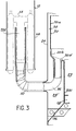
- - sur la figure 3, une vue en coupe à plus grande échelle illustrant une première variante de réalisation de l'invention;
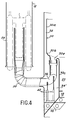
- - sur la figure 4, une vue comparable à la figure 3 illustrant une deuxième variante de réalisation de l'invention, et
- - sur la figure 5, une vue en coupe verticale du réacteur nucléaire montrant la partie interne du dispositif de manutention des assemblages.
- - In Figure 1, a vertical sectional view of the nuclear reactor showing a pump and an intermediate exchanger;
- in FIG. 2, a half-view in horizontal section along the line II-II in FIG. 1;
- - In Figure 3, a sectional view on a larger scale illustrating a first alternative embodiment of the invention;
- in FIG. 4, a view comparable to FIG. 3 illustrating a second variant embodiment of the invention, and
- - In Figure 5, a vertical sectional view of the nuclear reactor showing the internal part of the assembly handling device.
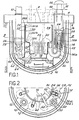
Sur la figure 1, on a représenté l'ensemble du réacteur nucléaire selon l'invention. De façon connue, on retrouve la cuve principale 2 suspendue à la dalle de fermeture supérieure 4 qui repose elle-même sur le massif de confinement 6. Cette dalle 4 comporte un ensemble de bouchons tournants excentrés 8. La dalle 4 sert également au supportage des pompes primaires 10 et des échangeurs intermédiaires 12, organes qui seront décrits plus en détail ultérieurement. La cuve principale 2 est doublée extérieurement par une cuve de sécurité 14 qui est également suspendue à la dalle de fermeture 4. Enfin, on trouve un baffle 15 solidaire de la cuve principale 2 qui sert à assurer de façon connue un refroidissement de la cuve principale 2 et en particulier de sa partie supérieure.In Figure 1, there is shown the entire nuclear reactor according to the invention. In known manner, there is the
A l'intérieur de la cuve principale 2, on trouve un platelage 16 supporté par la cuve principale 2, ce platelage servant d'une part de supportage au sommier 18 et accessoirement au faux-sommier dans lesquels sont fichés respectivement les assemblages, combustibles ou fertiles 20 constituant le coeur 22 du réacteur et les éléments formant la protection neutronique latérale 23 du coeur. Ces éléments sont par exemple constitués par des rondins métalliques qui forment plusieurs couronnes autour du coeur, les rondins étant disposés en quinconce. Le platelage 16 sert également au supportage de la cuve interne cylindrique 24. Il faut noter que le bord supérieur 24a de la cuve interne 24 est libre.Inside the
On voit qu'ainsi la cuve interne 24 sépare l'espace limité par la cuve principale 2 en une zone annulaire 26 dans laquelle sont logés principalement les pompes primaires 10 et les échangeurs intermédiaires 12 et un espace interne de forme générale cylindrique 28 qui contient le coeur. Dans l'espace annulaire 26, on trouve exclusivement un métal liquide qui peut être qualifié de froid. Selon l'invention, à l'intérieur de l'espace 28, on trouve un baffle portant la référence générale 30 qui est constitué par une partie supérieure cylindrique 30a, coaxiale à la cuve interne 24 et délimitant avec elle un espace annulaire 32 d'épaisseur réduite, par une partie de forme générale tronconique 30b et par une partie à nouveau cylindrique et à axe vertical 30c qui entoure la protection neutronique latérale 23 pour venir reposer sur le sommier 18 dans la variante représentée sur les figures. Le baffle 30 ainsi défini sépare à l'intérieur de l'espace interne 28 de la cuve interne 24 une zone 34 de sodium chaud entièrement disposée au-dessus du coeur du réacteur 22, c'est-à-dire au-dessus de la sortie du métal liquide chaud et un espace 34' entre le baffle 30 et la cuve interne 24.We see that thus the
Des conduites 36 relient la partie tronconique 30b du baffle interne 30 aux échangeurs de chaleur 12 pour alimenter ces derniers en métal liquide chaud. Ces conduites ont une forme générale en U et débouchent à la partie inférieure de la canalisation d'alimentation 72a de l'échangeur de chaleur en entourant cette canalisation sur une partie de sa longueur.
Dans une première variante de réalisation de l'invention représentée sur les figures 1 et 3, les conduites 36 sont réalisées d'un seul tenant et sont solidaires de la partie tronconique 30b du baffle 30, la paroi présentant de préférence une surépaisseur 30d au niveau de la jonction entre le baffle et chacune des conduites. Dans ce cas, le supportage des conduites 36 s'effectue par l'intermédiaire du baffle 30 qui repose comme on l'a vu sur le sommier 18. Bien entendu, le baffle 30 pourrait, dans une variante non représentée, reposer directement sur le platelage 16.In a first embodiment of the invention shown in Figures 1 and 3, the
Dans une deuxième variante de réalisation de l'invention représentée sur la figure 4, les conduites 36 sont indépendantes du baffle 30. Ce dernier présente alors, dans sa partie tronconique 30b, des tubulaires 30e sur lesquelles sont emboîtées les conduites 36, celles-ci étant supportées indépendamment du baffle 30 par des dispositifs de supportage 40 dont la partie inférieure est solidaire du platelage 16. Bien que cela ne soit pas indispensable en raison du supportage des conduites 36 par l'intermédiaire du baffle 30, des dispositifs de supportage du type des dispositifs 40 peuvent également être utilisés dans la première variante représentée sur la figure 3.In a second alternative embodiment of the invention shown in FIG. 4, the
Dans tous les cas, il est important de noter que l'extrémité supérieure 36a des conduites 36 n'est pas solidarisée avec l'échangeur de chaleur 12 correspondant. On comprend qu'ainsi, sous l'effet des dilatations thermiques dues aux diverses températures du métal liquide de refroidissement, l'ensemble constitué par le baffle 30 et les conduites 36 peut se déplacer librement - et qu'en même temps les conduites 36 peuvent se déplacer librement par rapport aux échangeurs 12. A propos des échangeurs de chaleur 12, il faut indiquer qu'ils peuvent être du type annulaire ou du type modulaire. Dans tous les cas, on réalise une étanchéité pneumatique (sans liaison mécanique) entre chaque conduite 36 et l'échangeur 12 correspondant.In all cases, it is important to note that the
Il est également important d'observer que le baffle 30, compte-tenu de son agencement, confine à l'intérieur de la cuve interne 24 le métal liquide chaud sortant du coeur du réacteur au-dessus de celui-ci. Cela signifie qu'il n'y a plus de circulation de sodium chaud dans l'espace annulaire situé entre la périphérie latérale du coeur 22 du réacteur et la cuve interne (espace 34'). Il n'y a donc plus lieu de prévoir des structures particulières pour éviter les mouvements de convection de métal liquide prenant naissance dans cette région, car le métal liquide chaud ne peut en aucun cas venir au contact du sommier 18 de supportage du coeur. Les problèmes liés au réchauffement de ce sommier sont donc supprimés.It is also important to observe that the
Pour compléter la description du réacteur nucléaire selon l'invention, il y a lieu d'indiquer que de préférence la cuve interne 24 est prolongée par des manchons tels que 50 qui entourent les conduites 36 d'alimentation des échangeurs de chaleur en métal liquide chaud. On réalise ainsi une structure qui permet d'améliorer l'isolation thermique entre l'intérieur des conduites 36 qui véhiculent un métal liquide chaud et l'intercuve 26 dans lequel on trouve le métal liquide froid. Il faut d'ailleurs observer que l'espace annulaire 34' entre le baffle 30 et la cuve interne 24 est rempli par du métal liquide à température intermédiaire, ce qui assure une certaine isolation thermique entre le métal liquide chaud dans l'espace 34 limité par le baffle 30 et le métal liquide froid remplissant l'espace annulaire 26. On a symbolisé par les conduites 56 et 58 la sortie et l'arrivée du fluide secondaire circulant dans l'échangeur 12. La sortie du métal liquide primaire se fait dans l'espace intercuve 26 en-dessous de la virole 58 entourant chaque échangeur de chaleur. L'échangeur représenté est un échangeur modulaire du type décrit dans la demande de brevet FR-A-2 385 067 déposée le 21 mars 1977. L'échangeur est constitué par une pluralité de modules d'échange disposés sur une couronne à l'intérieur d'une enveloppe externe. On pourrait également utiliser un échangeur annulaire du type décrit dans la demande de brevet FR-A-2 346 816 déposée le 29 mars 1976.To complete the description of the nuclear reactor according to the invention, it should be noted that preferably the
Le métal liquide froid sortant des échangeurs thermiques est repris par les buses d'entrée 60 des pompes primaires 10. La sortie de ces pompes primaires est reliée au sommier 18 du réacteur par des tubulaires 62 qui traversent la partie inférieure de la cuve interne 24. L'étanchéité entre le métal liquide froid dans l'espace intercuve 26 et le métal liquide à température intermédiaire dans l'espace annulaire 28 est assurée à ce niveau par des soufflets d'étanchéité tels que 64.The cold liquid metal leaving the heat exchangers is taken up by the
Le circuit du métal primaire de refroidissement dans le réacteur objet de l'invention découle de façon claire de la description précédente. En traversant le coeur 22 du réacteur, le métal liquide s'échauffe et pénètre dans l'espace 34 limité par le baffle 30. Ce métal liquide chaud est repris par les conduites 36 pour entrer dans les échangeurs de chaleur 12. Dans ces échangeurs, il cède sa chaleur au fluide secondaire et il ressort refroidi dans l'espace intercuve 26. Il est alors aspiré par les buses d'entrée 60 des pompes 10 et refoulé par les canalisations 62 dans le sommier 18 d'où il traverse à mouveau le coeur du réacteur.The circuit of the primary cooling metal in the reactor which is the subject of the invention follows clearly from the preceding description. By passing through the
Sur la figure 5, on a représenté la partie interne 100 du dispositif de manutention des assemblages constituant le coeur du réacteur. Comme cela est connu dans certains réacteurs nucléaires à neutrons rapides du type intégré, ce dispositif comprend essentiellement une rampe de manutention 102 et un pot de manutention 104. On voit que le bas de la rampe de manutention débouche dans l'espace 34' entre la cuve interne 24 et la protection neutronique 23, le pot de manutention étant bien sûr également logé dans cet espace.FIG. 5 shows the
On voit donc que grâce aux dispositions de l'invention, le dispositif de manutention se loge très facilement et très rationnellement.It can therefore be seen that, thanks to the provisions of the invention, the handling device can be accommodated very easily and very rationally.
Il découle de la description précédente que les caractéristiques de l'invention présentent de nombreux avantages par rapport au réacteur nucléaire à cuve interne cylindrique de l'art antérieur. La cuve interne qui supporte la différence de pression due aux pertes de charge est effectivement et rigoureusement cylindrique; mécaniquement, elle absorbe donc plus facilement ces contraintes. Le baffle interne 30 est de révolution et libre en dilatation, ce qui est favorable pour l'absorption des différentes contraintes mécaniques dues notamment aux dilatations thermiques.It follows from the above description that the characteristics of the invention have numerous advantages over the prior art cylindrical internal vessel nuclear reactor. The internal tank which supports the pressure difference due to the pressure losses is effectively and strictly cylindrical; mechanically, it therefore more easily absorbs these stresses. The
L'implantation du dispositif de manutention des assemblages s'insère naturellement entre la cuve interne 24 et le baffle 30 sans qu'il soit nécessaire de prévoir de structures supplémentaires dues à la traversée du baffle.The installation of the assembly handling device fits naturally between the
Le volume du collecteur de métal liquide chaud est réduit au minimum puisqu'il est limité au volume de la zone 34 définie par le baffle 30. La zone chaude est ainsi confinée; la protection thermique du sommier 18 et du platelage 16 est réalisée par ce confinement du métal liquide chaud dans la zone 34 et par la disposition des tuyaux 62 de refoulement du métal liquide froid dans le sommier.The volume of the hot liquid metal collector is reduced to a minimum since it is limited to the volume of the
Enfin, lorsque des dispositifs de supportage 40 supportent les conduites de sortie du métal liquide chaud 36, ces dispositifs permettent de limiter les problèmes dus aux vibrations produites par l'écoulement du métal liquide chaud dans ces conduites 36 et assurent une meilleure tenue aux séismes.Finally, when
Claims (8)
Applications Claiming Priority (2)
| Application Number | Priority Date | Filing Date | Title |
|---|---|---|---|
| FR7908793 | 1979-04-06 | ||
| FR7908793A FR2453472A1 (en) | 1979-04-06 | 1979-04-06 | NUCLEAR REACTOR WITH FAST NEUTRALS AND INTERNAL CYLINDRICAL TANK |
Publications (2)
| Publication Number | Publication Date |
|---|---|
| EP0018262A1 EP0018262A1 (en) | 1980-10-29 |
| EP0018262B1 true EP0018262B1 (en) | 1984-01-04 |
Family
ID=9224081
Family Applications (1)
| Application Number | Title | Priority Date | Filing Date |
|---|---|---|---|
| EP80400450A Expired EP0018262B1 (en) | 1979-04-06 | 1980-04-03 | Fast neutron nuclear reactor with an internal cylindrical vessel |
Country Status (6)
| Country | Link |
|---|---|
| US (1) | US4351794A (en) |
| EP (1) | EP0018262B1 (en) |
| JP (1) | JPS55135783A (en) |
| DE (1) | DE3066044D1 (en) |
| ES (1) | ES8103429A1 (en) |
| FR (1) | FR2453472A1 (en) |
Families Citing this family (7)
| Publication number | Priority date | Publication date | Assignee | Title |
|---|---|---|---|---|
| FR2497388A1 (en) * | 1980-12-30 | 1982-07-02 | Commissariat Energie Atomique | NUCLEAR REACTOR COOLED BY A LIQUID METAL AND COMPRISING A COOLED COLD BOTTOM |
| FR2506992B1 (en) * | 1981-05-27 | 1986-08-22 | Commissariat Energie Atomique | FAST NEUTRAL NUCLEAR REACTOR |
| FR2508225A1 (en) * | 1981-06-19 | 1982-12-24 | Novatome | DEVICE FOR CONNECTION BETWEEN THE PRIMARY PUMP DELIVERY DUCT AND A SOLIDARITY CONDUIT OF THE HEART SUPPORT OF A QUICK-NEUTRON NUCLEAR REACTOR |
| FR2541496A1 (en) * | 1983-02-22 | 1984-08-24 | Commissariat Energie Atomique | FAST NEUTRON NUCLEAR REACTOR WITH LONG INTERNAL STRUCTURE |
| JPS59168392A (en) * | 1983-03-16 | 1984-09-22 | 財団法人 電力中央研究所 | Tank type fast breeder |
| JPS6089795A (en) * | 1983-10-24 | 1985-05-20 | 財団法人電力中央研究所 | Fast breeder reactor |
| US5189402A (en) * | 1987-05-14 | 1993-02-23 | Advanced Interaction, Inc. | Content addressable video system for image display |
Family Cites Families (15)
| Publication number | Priority date | Publication date | Assignee | Title |
|---|---|---|---|---|
| FR2096841B1 (en) * | 1970-07-06 | 1974-12-20 | Babcock Atlantique Sa | |
| FR2101019B1 (en) * | 1970-08-07 | 1973-12-21 | Commissariat Energie Atomique | |
| FR2133530B1 (en) * | 1971-04-16 | 1975-01-17 | Commissariat Energie Atomique | |
| FR2220847B1 (en) * | 1973-03-07 | 1975-10-31 | Commissariat Energie Atomique | |
| DE2335378A1 (en) * | 1973-07-12 | 1975-01-30 | Stelag Konstruktion | METHOD AND DEVICE FOR DRIVING SHAFTS |
| FR2246941B1 (en) * | 1973-10-09 | 1976-11-19 | Commissariat Energie Atomique | |
| US4056438A (en) * | 1973-10-18 | 1977-11-01 | Commissariat A L'energie Atomique | Liquid sodium cooled fast reactor |
| GB1448994A (en) * | 1973-12-06 | 1976-09-08 | Atomic Energy Authority Uk | Liquid metal cooled fast breeder nuclear reactors |
| DE2535378A1 (en) * | 1975-08-08 | 1977-02-24 | Interatom | Pressure wave damping of liquid metal cooled reactors - by plenum chambers in primary circuit to protect heat exchanger |
| FR2370344A2 (en) * | 1975-11-26 | 1978-06-02 | Commissariat Energie Atomique | Nuclear reactor cooling system - adapted for cooling suspended inner vessel, incorporates baffles forming flow spaces for cold liq. sodium |
| FR2337408A1 (en) * | 1975-12-29 | 1977-07-29 | Alsthom Cgee | Nuclear reactor cooled by liquid metal - has exchangers and inner vessel joined at toric surfaces to distribute stresses |
| FR2346816A1 (en) * | 1976-03-29 | 1977-10-28 | Commissariat Energie Atomique | Heat exchanger connector for fast neutron reactor - gives better distribution of liq. and better thermal insulation |
| FR2357987A1 (en) * | 1976-07-06 | 1978-02-03 | Commissariat Energie Atomique | FAST NEUTRON NUCLEAR REACTOR |
| DE2705010A1 (en) * | 1977-02-07 | 1978-08-10 | Kraftwerk Union Ag | DEVICE FOR COUPLING PIPING IN REACTOR PRESSURE VESSELS, PREFERABLY THE PIPING OF THE FEED WATER DISTRIBUTOR |
| FR2394700A1 (en) * | 1977-06-17 | 1979-01-12 | Commissariat Energie Atomique | CIRCULATION PUMP, ESPECIALLY FOR LIQUID METAL COOLING THE CORE OF A NUCLEAR REACTOR WITH QUICK NEUTRON |
-
1979
- 1979-04-06 FR FR7908793A patent/FR2453472A1/en active Granted
-
1980
- 1980-03-28 US US06/134,898 patent/US4351794A/en not_active Expired - Lifetime
- 1980-04-02 ES ES490238A patent/ES8103429A1/en not_active Expired
- 1980-04-03 DE DE8080400450T patent/DE3066044D1/en not_active Expired
- 1980-04-03 EP EP80400450A patent/EP0018262B1/en not_active Expired
- 1980-04-04 JP JP4451880A patent/JPS55135783A/en active Pending
Also Published As
| Publication number | Publication date |
|---|---|
| EP0018262A1 (en) | 1980-10-29 |
| JPS55135783A (en) | 1980-10-22 |
| ES490238A0 (en) | 1981-02-16 |
| FR2453472B1 (en) | 1982-04-30 |
| FR2453472A1 (en) | 1980-10-31 |
| ES8103429A1 (en) | 1981-02-16 |
| US4351794A (en) | 1982-09-28 |
| DE3066044D1 (en) | 1984-02-09 |
Similar Documents
| Publication | Publication Date | Title |
|---|---|---|
| EP0344041A1 (en) | Nuclear reactor emergency cooling water feeding device | |
| EP0246969B1 (en) | Small pressurized-water nuclear reactor with natural circulation | |
| EP0018262B1 (en) | Fast neutron nuclear reactor with an internal cylindrical vessel | |
| EP0153225B1 (en) | Heat-exchanger with emergency cooling arrangements and fast nuclear reactor having such a heat-exchanger | |
| EP0006800B1 (en) | Liquid-metal cooled fast nuclear reactor | |
| FR2606924A1 (en) | PASSIVE EMERGENCY SHUTDOWN HEAT REMOVAL SYSTEM FOR A LIQUID METAL NUCLEAR REACTOR | |
| EP0055963B1 (en) | Liquid metal cooled nuclear reactor comprising a main vessel cooled at the bottom | |
| EP0067103B1 (en) | Fast breeder nuclear reactor | |
| EP0105781B1 (en) | Secondary thermal carrier circuit for a liquid metal-cooled nuclear reactor, and steam generator for such a circuit | |
| EP0020264B1 (en) | Semi-modular type heat exchanger for nuclear reactor | |
| EP0258131B1 (en) | Emergency cooling arrangement for fast neutron reactor | |
| EP0048672B1 (en) | Nuclear reactor with integrated heat exchangers | |
| EP0173602A1 (en) | Emergency heat exchanger for cooling the primary fluid of a nuclear reactor, and method of assembling this heat exchanger | |
| EP0006801A1 (en) | Liquid-metal cooled fast nuclear reactor | |
| FR2555794A1 (en) | Fast-neutron nuclear reactor fitted with emergency cooling means | |
| EP0108690B1 (en) | Heat exchanger for high temperature fluids in which one of the fluids enters and leaves by way of the superior part of the exchanger | |
| EP0156689B1 (en) | Fast nuclear reactor with suspended main vessel and lid | |
| EP0095428B1 (en) | Cooling device using gas for the vessel cover of a nuclear reactor | |
| EP0161949B1 (en) | Liquid metal-cooled nuclear reactor | |
| FR2680597A1 (en) | Internal structure of a fast neutron nuclear reactor | |
| EP0122190B1 (en) | Steam generator for a liquid metal-cooled reactor | |
| EP0064920B1 (en) | Apparatus for steam generation and heat exchange in a fast breeder reactor | |
| EP0094294B1 (en) | Reactor vessel supports | |
| EP0206921B1 (en) | Heat exchanger with coaxial u-tubes and intermediate circulation of neutral gas, and fast neutron reactor comprising such a heat exchanger | |
| EP0144256B1 (en) | Thermal protection device for a fast neutrons nuclear reactor component |
Legal Events
| Date | Code | Title | Description |
|---|---|---|---|
| PUAI | Public reference made under article 153(3) epc to a published international application that has entered the european phase |
Free format text: ORIGINAL CODE: 0009012 |
|
| AK | Designated contracting states |
Designated state(s): BE DE GB IT NL |
|
| 17P | Request for examination filed |
Effective date: 19810327 |
|
| ITF | It: translation for a ep patent filed |
Owner name: JACOBACCI & PERANI S.P.A. |
|
| GRAA | (expected) grant |
Free format text: ORIGINAL CODE: 0009210 |
|
| AK | Designated contracting states |
Designated state(s): BE DE GB IT NL |
|
| REF | Corresponds to: |
Ref document number: 3066044 Country of ref document: DE Date of ref document: 19840209 |
|
| PGFP | Annual fee paid to national office [announced via postgrant information from national office to epo] |
Ref country code: DE Payment date: 19840326 Year of fee payment: 5 |
|
| PGFP | Annual fee paid to national office [announced via postgrant information from national office to epo] |
Ref country code: BE Payment date: 19840630 Year of fee payment: 5 |
|
| PLBE | No opposition filed within time limit |
Free format text: ORIGINAL CODE: 0009261 |
|
| STAA | Information on the status of an ep patent application or granted ep patent |
Free format text: STATUS: NO OPPOSITION FILED WITHIN TIME LIMIT |
|
| 26N | No opposition filed | ||
| PGFP | Annual fee paid to national office [announced via postgrant information from national office to epo] |
Ref country code: NL Payment date: 19860430 Year of fee payment: 7 |
|
| BERE | Be: lapsed |
Owner name: COMMISSARIAT A L'ENERGIE ATOMIQUE ETABLISSEMENT D Effective date: 19870430 |
|
| PG25 | Lapsed in a contracting state [announced via postgrant information from national office to epo] |
Ref country code: NL Effective date: 19871101 |
|
| NLV4 | Nl: lapsed or anulled due to non-payment of the annual fee | ||
| GBPC | Gb: european patent ceased through non-payment of renewal fee | ||
| PG25 | Lapsed in a contracting state [announced via postgrant information from national office to epo] |
Ref country code: DE Effective date: 19880101 |
|
| PG25 | Lapsed in a contracting state [announced via postgrant information from national office to epo] |
Ref country code: GB Effective date: 19881118 |
|
| PG25 | Lapsed in a contracting state [announced via postgrant information from national office to epo] |
Ref country code: BE Effective date: 19890430 |