EP0020264A1 - Semi-modular type heat exchanger for nuclear reactor - Google Patents
Semi-modular type heat exchanger for nuclear reactor Download PDFInfo
- Publication number
- EP0020264A1 EP0020264A1 EP80400749A EP80400749A EP0020264A1 EP 0020264 A1 EP0020264 A1 EP 0020264A1 EP 80400749 A EP80400749 A EP 80400749A EP 80400749 A EP80400749 A EP 80400749A EP 0020264 A1 EP0020264 A1 EP 0020264A1
- Authority
- EP
- European Patent Office
- Prior art keywords
- base plate
- support
- secondary fluid
- exchanger
- modules
- Prior art date
- Legal status (The legal status is an assumption and is not a legal conclusion. Google has not performed a legal analysis and makes no representation as to the accuracy of the status listed.)
- Granted
Links
Images


Classifications
-
- F—MECHANICAL ENGINEERING; LIGHTING; HEATING; WEAPONS; BLASTING
- F28—HEAT EXCHANGE IN GENERAL
- F28D—HEAT-EXCHANGE APPARATUS, NOT PROVIDED FOR IN ANOTHER SUBCLASS, IN WHICH THE HEAT-EXCHANGE MEDIA DO NOT COME INTO DIRECT CONTACT
- F28D1/00—Heat-exchange apparatus having stationary conduit assemblies for one heat-exchange medium only, the media being in contact with different sides of the conduit wall, in which the other heat-exchange medium is a large body of fluid, e.g. domestic or motor car radiators
- F28D1/02—Heat-exchange apparatus having stationary conduit assemblies for one heat-exchange medium only, the media being in contact with different sides of the conduit wall, in which the other heat-exchange medium is a large body of fluid, e.g. domestic or motor car radiators with heat-exchange conduits immersed in the body of fluid
- F28D1/0206—Heat exchangers immersed in a large body of liquid
- F28D1/0213—Heat exchangers immersed in a large body of liquid for heating or cooling a liquid in a tank
-
- G—PHYSICS
- G21—NUCLEAR PHYSICS; NUCLEAR ENGINEERING
- G21C—NUCLEAR REACTORS
- G21C1/00—Reactor types
- G21C1/02—Fast fission reactors, i.e. reactors not using a moderator ; Metal cooled reactors; Fast breeders
- G21C1/03—Fast fission reactors, i.e. reactors not using a moderator ; Metal cooled reactors; Fast breeders cooled by a coolant not essentially pressurised, e.g. pool-type reactors
-
- F—MECHANICAL ENGINEERING; LIGHTING; HEATING; WEAPONS; BLASTING
- F28—HEAT EXCHANGE IN GENERAL
- F28D—HEAT-EXCHANGE APPARATUS, NOT PROVIDED FOR IN ANOTHER SUBCLASS, IN WHICH THE HEAT-EXCHANGE MEDIA DO NOT COME INTO DIRECT CONTACT
- F28D21/00—Heat-exchange apparatus not covered by any of the groups F28D1/00 - F28D20/00
- F28D2021/0019—Other heat exchangers for particular applications; Heat exchange systems not otherwise provided for
- F28D2021/0054—Other heat exchangers for particular applications; Heat exchange systems not otherwise provided for for nuclear applications
-
- Y—GENERAL TAGGING OF NEW TECHNOLOGICAL DEVELOPMENTS; GENERAL TAGGING OF CROSS-SECTIONAL TECHNOLOGIES SPANNING OVER SEVERAL SECTIONS OF THE IPC; TECHNICAL SUBJECTS COVERED BY FORMER USPC CROSS-REFERENCE ART COLLECTIONS [XRACs] AND DIGESTS
- Y02—TECHNOLOGIES OR APPLICATIONS FOR MITIGATION OR ADAPTATION AGAINST CLIMATE CHANGE
- Y02E—REDUCTION OF GREENHOUSE GAS [GHG] EMISSIONS, RELATED TO ENERGY GENERATION, TRANSMISSION OR DISTRIBUTION
- Y02E30/00—Energy generation of nuclear origin
- Y02E30/30—Nuclear fission reactors
Definitions
- the present invention relates to a heat exchanger of the semi-modular type for a nuclear reactor and more particularly for a fast neutron nuclear reactor cooled by a liquid metal and of the integrated type.
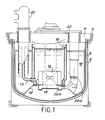
- Figure 1 a vertical sectional view of an integrated reactor.
- the main tank 6 which encloses the entire primary circuit is suspended from this slab 4 and doubled by a safety tank 8.
- the internal tank 10 Inside the main tank 6, there is an internal tank 10 which is supported by a platform 12 resting on the main tank.
- the internal tank separates, on the one hand, the hot liquid metal in general from the sodium, leaving the core 16 supported by the decking and, on the other hand, the cold metal contained in the annular space 18 comprised between the main tank 6 and the internal tank 10.
- the hot sodium leaving the core is taken up by pipes 19 which introduce the hot sodium leaving the core into intermediate exchangers 20.
- Pumps 22 also housed in the annular space 18 provide the circulation of the primary fluid, by reinjecting this liquid metal at the base of the heart into the bed base 14 by means of pipes 22b.
- the present invention relates to a heat exchanger capable of absorbing more easily than the exchangers according to the prior art the thermal expansions of which it is the seat due to the temperature differences of the two fluids circulating in the exchanger.
- the exchanger according to the invention can be described as semi-modular. Indeed, it is constituted by several exchange modules, but these exchange modules comprise a supply of common primary liquid metal and they are mechanically connected to each other.
- Each module includes a bundle of straight or “substantially” straight tubes.
- This latter expression means that the tubes can comprise, over a fraction of their length, in particular at their ends, portions in the form of a helix portion intended to give the tubes greater flexibility.
- the invention relates to a heat exchanger for a nuclear reactor, the vessel of which is closed by a slab, the exchanger being of the type comprising, inside an external shroud with vertical axis, a plurality of heat exchange modules with substantially straight tubes, each of these modules comprising an inlet chamber and an outlet chamber for secondary fluid and means for introducing and leaving the primary fluid in said exchange modules; it is characterized in that it comprises a base plate fixed on its periphery to said external ferrule, means for supporting said external ferrule by the slab, ferrules for supporting said modules, each ferrule passing through said base plate and being connected, on the one hand to the upper end of a module and, on the other hand, to said base plate, a plurality of pipes respectively for supplying and discharging the secondary fluid passing tightly through said plate base, an inlet manifold and an outlet manifold for the secondary fluid disposed inside said outer shroud above said base plate, said manifolds being connected respectively to the supply and discharge pipes of the secondary fluid , means for supporting
- the means su p porting manifolds comprise a support structure secured by its lower end to the base plate.
- the means for supporting the collectors comprise a support plate, the periphery of which is fixed to the external shell at the level of the means for supporting the external shell by the slab, and a support structure integral with its lower end of the support plate.
- the portions of the secondary fluid supply and discharge pipes included between the base plate and said manifolds have the shape of a propeller portion making an angle of approximately 180 °.
- the outlet chambers are located in the upper part of the modules exchange and acua .
- tion ev lines of the secondary fluid are arranged inside and coaxially to the rings support forces the latter ensuring the sealed penetration of the base plate by said secondary fluid discharge pipes.
- the ferrules play a double role.
- the exchanger comprises an outer ring 30 open at its lower end 30a and provided at its upper end with a support flange 30b.
- This outer shell 30 is extended by an upper dome 32 connected to the shell.
- the flange 30b which is held by a counter flange 30'b is supported on the slab 4 via the flange 33 and the support sleeve 34. It will be understood that thus the assembly of the vircle 30 and the dome 32 is supported by the flange 30b which rests on the slab 4.
- the internal space limited by the ferrule 30 is separated by a horizontal base plate 36 into a lower space 36a and an upper space 36b.
- the lower space contains the heat exchange modules such as 38
- the upper space contains the secondary fluid inlet and outlet manifolds (liquid sodium) circulating in the exchange modules 38.
- Each exchange module 38 is constituted in known manner by substantially straight exchange tubes 40 mounted between an upper tube plate 42 and a lower tube plate 44 connected respectively to outlet chambers 42a and inlet 44a.
- These exchange tubes are surrounded by an external ferrule 46 comprising a lower outlet window 48 for the primary fluid and an upper inlet window 50 for this same primary fluid.
- the inlet chamber 44a is connected to a supply line 52a which will be described in more detail later and the outlet chamber 42a is connected to a discharge line 54a which will also be described in more detail later.
- 56 have been symbolized by structures which make it possible to maintain the exchange tubes 40 of the exchange modules 48.
- each exchange module 38 is suspended by its upper part from the base plate 36.
- This suspension is advantageously carried out by means of a support ring 60 whose lower end 60a is welded to the outlet chamber 42a, and whose upper end 60b which passes through the plate 36 by a bore 62 is welded to a sleeve 61 itself secured to the base plate 36.
- each module d The exchange is rigidly supported by the base plate.
- the pipes 54a are arranged inside the ferrules 60. The sealed passage of the base plate 36 is thus carried out by the pipes 54a.
- pipes 72 make it possible to introduce argon into the upper region of the inlet window 50 of each module in order to possibly be able to stop the supply of primary sodium to the module in question.
- the conduits 52a have a curved part and rise up inside the ferrule 30 parallel to the modules.
- the tightness of the crossing of these pipes 52a through the base plate 36 is ensured by metallic expansion bellows 76 which are fixed on the one hand to the base plate 36 and on the other hand to the external wall of the pipes 52a.
- metallic expansion bellows 76 which are fixed on the one hand to the base plate 36 and on the other hand to the external wall of the pipes 52a.
- a cylindrical support structure 80 integral by its lower end 80a with the upper face of the base plate 36 supports on the one hand a cold collector 82, and on the other hand, a hot collector 84 which is disposed above the collector cold 82.
- the outlet pipes 54a of the hot secondary liquid metal are connected at their upper end to the hot manifold 84.
- these pipes 52a In the upper part of the shell 30, and in the dome 32, these pipes 52a have the shape of a portion d propeller making an angle of 180 °. They can thus absorb part of the expansion of these pipes due to the temperatures occurring in the exchanger.
- the hot collector is provided with a large pipe 86 for leaving the secondary hot liquid metal going to a steam generator as is well known in fast neutron reactors cooled by liquid sodium.
- the inlet conduits 52a of the cold secondary liquid metal are connected to the cold manifold 82 and each form inside the ferrule 30 a helix corresponding to an angle of 180 °.
- the cold collector 82 is provided with a large pipe 88 used for the introduction of the cold secondary liquid metal.
- the part 80 ′ of the central structure 80 provides the mechanical connection between the two cold and hot collectors, respectively.
- the hot manifold is provided at its upper part with a guide ring 90 which cooperates with a sleeve 92 integral with the upper part of the dome 32.
- the bore g e collectors and biological protection plates is no longer carried by the base plate 36 but through a plate Bracketing 110 disposed above the plate 36, at the flange bore g e 30b.
- the same reference numbers have been used to designate the elements identical to those of the first variant.
- the inlet 82 and outlet 84 collectors are supported by a support plate 110 pinched between the two parts of the support flange 30b belonging to the ferrule 30 and to the dome 32. More specifically, the inlet manifold 82 rests on the plate 110 by means of a support 112, the outlet manifold 84 being disposed above the inlet manifold and resting on the latter by through a central structure 114 similar to part 80 'in the variant of FIG. 2a.
- the collectors 82 and 84 are both arranged above the support plate 110 and the collector outlet 84 is always provided at its upper part with a ferrule 90 received in a sleeve 92 integral with the upper part of dome 32.
- the biological protection plates 94 are suspended from the plate bore 110 g e for example by means of rods 116 provided with suitable spacers 118, the plates 94 being disposed at the faceplate 4 and above the base plate 36.
- supply lines 52a and discharge 52b pass through suitable notches formed in the support plate 110.
- a spacer assembly 100 which includes a central rod 102 suspended in below the base plate 36 and the radial fins 104 ending in portions of tubes 106 which ensure the mutual setting of the introduction pipes 70, thus in particular avoiding the vibrations of these pipes.
- the first intervention consists of locking an exchange module inside the tank itself.
- the second intervention consists in the removal of an intermediate exchanger for a maintenance operation outside the nuclear reactor vessel.
- the large pipes 86 and 88 are cut and the intermediate exchanger is extracted from the tank by detaching the flange 30b.
- the ferrule 30 is cut approximately 300 mm above the base plate 36.
- the conduits 52a and 54a are also cut.
- the weld of the support ring 60 is ground on the sleeve 61 secured to the base plate 36.
- the module 38 can then be deposited on which it is necessary to intervene.
- the semi-modular exchanger according to the invention has many advantages compared to those of the prior art.
- the thermal expansions of the secondary inlet and outlet pipes are better absorbed without, however, complicating the structure.
- the exchanger has better behavior in the event of earthquakes to which the reactor would be subjected.
Abstract
Echangeur de chaleur intermédiaire comportant une plaque de base (36) fixée sur sa périphérie à une virole externe (30), des moyens pour faire supporter ladite virole externe (30) par une dalle, des viroles de supportage (60) des modules (38), chaque virole (60) traversant ladite plaque de base (36) et étant raccordée, d'une part (60a) à l'extrémité supérieure d'un module (38) et, d'autre part (60b) à ladite plaque de base (36), une pluralité de conduites respectivement d'alimentation (52a) et d'évacuation (54a) du fluide secondaire traversant de façon étanche ladite plaque de base (36), un collecteur d'entrée (44a) et un collecteur de sortie (42a) du fluide secondaire disposés à l'intérieur de ladite virole externe (30) au-dessus de ladite plaque de base (36), et des moyens de supportage (60) desdits collecteurs (42a) reposant sur ladite plaque de base (36). Application aux réacteurs nucléaires, notamment à neutrons rapides.Intermediate heat exchanger comprising a base plate (36) fixed on its periphery to an external ferrule (30), means for making said external ferrule (30) support by a slab, support ferrules (60) of the modules (38 ), each ferrule (60) passing through said base plate (36) and being connected, on the one hand (60a) to the upper end of a module (38) and, on the other hand (60b) to said plate base (36), a plurality of lines for supplying (52a) and discharging (54a) respectively of the secondary fluid sealingly passing through said base plate (36), an inlet manifold (44a) and a manifold outlet (42a) of the secondary fluid disposed inside said outer ring (30) above said base plate (36), and support means (60) of said manifolds (42a) resting on said plate base (36). Application to nuclear reactors, in particular fast neutrons.
Description
La présente invention a pour objet un échangeur de chaleur du type semi-modulaire pour réacteur nucléaire et plus particulièrement pour réacteur nucléaire à neutrons rapides refroidis par un métal liquide et du type intégré.The present invention relates to a heat exchanger of the semi-modular type for a nuclear reactor and more particularly for a fast neutron nuclear reactor cooled by a liquid metal and of the integrated type.
Afin de mieux faire comprendre l'invention, on a représenté sur la figure 1, une vue en coupe verticale d'un réacteur intégré. Sur cette figure, on retrouve de façon connue le massif bétonné 2 fermé à sa partie supérieure par la dalle 4. La cuve principale 6 qui renferme l'ensemble du circuit primaire est suspendue à cette dalle 4 et doublée par une cuve de sécurité 8.To better understand the invention, there is shown in Figure 1, a vertical sectional view of an integrated reactor. In this figure, we find in a known manner the concrete block 2 closed at its upper part by the slab 4. The
A l'intérieur de la cuve principale 6, on trouve une cuve interne 10 qui est supportée par un platelage 12 reposant sur la cuve principale. La cuve interne sépare, d'une part, le métal liquide chaud en général du sodium, sortant du coeur 16 supporté par le platelage et, d'autre part, le métal froid contenu dans l'espace annulaire 18 compris entre la cuve principale 6 et la cuve interne 10. Dans ce type de réacteur, le sodium chaud sortant du coeur est repris par des conduites 19 qui introduisent le sodium chaud sortant du coeur dans des échangeurs intermédiaires 20. Des pompes 22 logées également dans l'espace annulaire 18 assurent la mise en circulation du fluide primaire, en réinjectant ce métal liquide à la base du coeur dans le sommier 14 par l'intermédiaire de conduites 22b.Inside the
On connaît déjà des réacteurs nucléaires de ce type utilisant des échangeurs de chaleur intermédiaires du type modulaire. On peut par exemple citer à ce propos la demande de brevet français n° 77 08384 déposée le 21 mars 1977 au nom du demandeur pour "Echangeur thermique annulaire" et la demande de certificat d'addition n° EN 77 21451 déposée le 12 juillet 1977 au nom du demandeur pour "Eciian- geur thermique annulaire".Nuclear reactors of this type are already known using intermediate heat exchangers of the modular type. We can for example cite in this regard the French patent application n ° 77 08384 filed on March 21, 1977 in the name of the applicant for "Annular heat exchanger" and the request for addition certificate n ° EN 77 21451 filed on July 12, 1977 in the name of the applicant for "Annular thermal exchanger".
La présente invention concerne un échangeur de chaleur apte à absorber plus facilement que les échangeurs selon l'art antérieur les dilatations thermiques dont il est le siège du fait des différences de température des deux fluides circulant dans l'échangeur.The present invention relates to a heat exchanger capable of absorbing more easily than the exchangers according to the prior art the thermal expansions of which it is the seat due to the temperature differences of the two fluids circulating in the exchanger.
L'échangeur selon l'invention peut être qualifié de semi-modulaire. En effet, il est constitué par plusieurs modules d'échange, mais ces modules d'échange comportent une alimentation en métal liquide primaire commune et ils sont mécaniquement reliés les uns aux autres.The exchanger according to the invention can be described as semi-modular. Indeed, it is constituted by several exchange modules, but these exchange modules comprise a supply of common primary liquid metal and they are mechanically connected to each other.
Chaque module comprend un faisceau de tubes droits ou "sensiblement" droits. Cette dernière expression signifie que les tubes peuvent comporter sur une fraction de leur longueur, notamment à leurs extrémités, des parties en forme de portion d'hélice destinées à conférer aux tubes une plus grande souplesse.Each module includes a bundle of straight or "substantially" straight tubes. This latter expression means that the tubes can comprise, over a fraction of their length, in particular at their ends, portions in the form of a helix portion intended to give the tubes greater flexibility.
L'invention concerne un échangeur de chaleur pour un réacteur nucléaire dont la cuve est obturée par une dalle, l'échangeur étant du type comportant à l'intérieur d'une virole externe à axe vertical, une pluralité de modules d'échange thermique à tubes sensiblement droits, chacun de ces modules comprenant une chambre d'entrée et une chambre de sortie de fluide secondaire et des moyens pour l'introduction et la sortie du fluide primaire dans lesdits modules d'échange ; il se caractérise en ce qu'il comprend une plaque de base fixée sur sa périphérie à ladite virole externe, des moyens pour faire supporter ladite virole externe par la dalle, des viroles de supportage desdits modules, chaque virole traversant ladite plaque de base et étant raccordée, d'une part à l'extrémité supérieure d'un module et, d'autre part, à ladite plaque de base, une pluralité de conduites respectivement d'alimentation et d'évacuation du fluide secondaire traversant de façon étanche ladite plaque de base, un collecteur d'entrée et un collecteur de sortie du fluide secondaire diposés à l'intérieur de ladite virole externe au-dessus de ladite plaque de base, lesdits collecteurs étant raccordés respectivement aux conduites d'alimentation et d'évacuation du fluide secondaire, des moyens de supportage desdits collecteurs et une pluralité de plaques de protection biologique disposées dans la virole externe au-dessus de la plaque de base et au niveau de ladite dalle, lesdites plaques de protection étant supportées par les moyens de supportage desdits collecteurs, lesdites plaques de protection permettant le passage des conduites d'alimentation et d'évacuation en fluide secondaire.The invention relates to a heat exchanger for a nuclear reactor, the vessel of which is closed by a slab, the exchanger being of the type comprising, inside an external shroud with vertical axis, a plurality of heat exchange modules with substantially straight tubes, each of these modules comprising an inlet chamber and an outlet chamber for secondary fluid and means for introducing and leaving the primary fluid in said exchange modules; it is characterized in that it comprises a base plate fixed on its periphery to said external ferrule, means for supporting said external ferrule by the slab, ferrules for supporting said modules, each ferrule passing through said base plate and being connected, on the one hand to the upper end of a module and, on the other hand, to said base plate, a plurality of pipes respectively for supplying and discharging the secondary fluid passing tightly through said plate base, an inlet manifold and an outlet manifold for the secondary fluid disposed inside said outer shroud above said base plate, said manifolds being connected respectively to the supply and discharge pipes of the secondary fluid , means for supporting said collectors and a plurality of biological protection plates arranged in the outer shell above the base plate and at the level of said slab, said protection plates being supported by the support means for said collectors, said plates protection allowing the passage of the supply and discharge pipes in secondary fluid.
Selon une première variante de réalisation, les moyens de supportage des collecteurs comprennent une structure de supportage solidaire par son extrémité inférieure de la plaque de base.According to a first alternative embodiment, the means su p porting manifolds comprise a support structure secured by its lower end to the base plate.
Selon une deuxième variante, les moyens de supportage des collecteurs comprennent une plaque de supportage dont la périphérie est fixée à la virole externe au niveau des moyens pour faire supporter la virole externe par la dalle, et une structure de supportage solidaire par son extrémité inférieure de la plaque de supportage.According to a second variant, the means for supporting the collectors comprise a support plate, the periphery of which is fixed to the external shell at the level of the means for supporting the external shell by the slab, and a support structure integral with its lower end of the support plate.
De préférence, les portions des conduites d'alimentation et d'évacuation en fluide secondaire comprises entre la plaque de base et lesdits collecteurs, ont la forme d'une portion d'hélice faisant un angle d'environ 180°.Preferably, the portions of the secondary fluid supply and discharge pipes included between the base plate and said manifolds have the shape of a propeller portion making an angle of approximately 180 °.
Ainsi,on peut absorber les dilatations thermiques entre les modules d'échange thermique et les collecteurs "chaud" et "froid".Thus, it is possible to absorb the thermal expansions between the heat exchange modules and the "hot" and "cold" collectors.
De préférence encore, les chambres de sortie sont situées à la partie supérieure des modules d'échange et les conduites d'évacua.tion du fluide secondaire sont disposées à l'intérieur et coaxialement aux viroles de supportage, ces dernières assurant la traversée étanche de la plaque de base par lesdites conduites d'évacuation de fluide secondaire.More preferably, the outlet chambers are located in the upper part of the modules exchange and acua .tion ev lines of the secondary fluid are arranged inside and coaxially to the rings support forces the latter ensuring the sealed penetration of the base plate by said secondary fluid discharge pipes.
On voit qu'ainsi, les viroles jouent un double rôle. D'une part, elles solidarisent les modules à la plaque de base en assurant leur supportage et, d'autre part, elles assurent la traversée étanche de la plaque de base, ce qui est nécessaire puisque celle-ci constitue le fond de la cloche de gaz inerte qui surmonte le fluide primaire dans l'échangeur intermédiaire.We see that thus, the ferrules play a double role. On the one hand, they secure the modules to the base plate while ensuring their support and, on the other hand, they ensure the watertight crossing of the base plate, which is necessary since the latter constitutes the bottom of the inert gas bell which overcomes the primary fluid in the intermediate exchanger.
On décrira maintenant à titre d'exemple non limitatif, deux variantes de réalisation de l'invention en se référant aux dessins annexés dans lesquels :
- - la figure 1, déjà décrite,représente une vue en coupe verticale d'un réacteur nucléaire à neutrons rapides du type intégré montrant l'implantation d'un échangeur intermédiaire,
- - la figure 2a, représente une vue en coupe verticale de la partie supérieure de l'échangeur selon une première variante de l'invention,
- - la figure 2b, représente une vue en coupe verticale de la partie inférieure de l'échangeur dont la partie supérieure est représentée sur la figure 2a,
- - les figures 3a à 3c, représentent des vues en section horizontale de l'échangeur intermédiaire selon respectivement les plans A-A, B-B et C-C de la figure 2b, et
- - la figure 4 représente une vue en coupe verticale de la partie supérieure de l'échangeur selon une deuxième variante de l'invention.
- FIG. 1, already described, represents a view in vertical section of a nuclear reactor with fast neutrons of the integrated type showing the installation of an intermediate exchanger,
- FIG. 2a represents a view in vertical section of the upper part of the exchanger according to a first variant of the invention,
- FIG. 2b represents a view in vertical section of the lower part of the exchanger, the upper part of which is shown in FIG. 2a,
- FIGS. 3a to 3c represent views in horizontal section of the intermediate exchanger according to the planes AA, BB and CC respectively of FIG. 2b, and
- - Figure 4 shows a vertical sectional view of the upper part of the exchanger according to a second variant of the invention.
Comme on le voit sur les figures 2a et 2b, l'échangeur comprend une virole externe 30 ouverte à son extrémité inférieure 30a et munie à son extrémité supérieure d'une bride de supportage 30b. Cette virole externe 30 est prolongée par un dôme supérieur 32 raccordé à la virole. La bride 30b, qui est maintenue par une contre-bride 30'b s'appuie sur la dalle 4 par l'intermédiaire de la bride 33 et du manchon 34 de supportage. On comprend qu'ainsi l'ensemble de la vircle 30 et du dôme 32 est supporté par la bride 30b qui s'appuie sur la dalle 4.As seen in Figures 2a and 2b, the exchanger comprises an
L'espace interne limité par la virole 30 est séparé par une plaque de base horizontale 36 en un espace inférieur 36a et en un espace supérieur 36b. Schématiquement, l'espace inférieur contient les modules d'échange thermique tels que 38, alors que l'espace supérieur contient les collecteurs d'entrée et de sortie du fluide secondaire (sodium liquide) circulant dans les modules d'échange 38. Chaque module d'échange 38 est constitué de façon connue par des tubes d'échange sensiblement droits 40 montés entre une plaque à tubes supérieure 42 et une plaque à tubes inférieure 44 raccordées respectivement à des chambres de sortie 42a et d'entrée 44a. Ces tubes d'échange sont entourés par une virole externe 46 comportant une fenêtre inférieure de sortie 48 pour le fluide primaire et une fenêtre d'entrée supérieure 50 pour ce même fluide primaire. La chambre d'entrée 44a est raccordée à une conduite d'alimentation 52a qui sera décrite plus en détail ultérieurement et la chambre de sortie 42a est raccordée à une conduite d'évacuation 54a qui sera également décrite plus en détail ultérieurement. On a symbolisé par 56 des structures qui permettent d'assurer le maintien des tubes d'échange 40 des modules d'échange 48.The internal space limited by the
Selon une caractéristique essentielle de l'invention, chaque module d'échange 38 est suspendu par sa partie supérieure à la plaque de base 36. Cette suspension est réalisée avantageusement par l'intermédiaire d'une virole de supportage 60 dont l'extrémité inférieure 60a est soudée sur la chambre de sortie 42a, et dont l'extrémité supérieure 60b qui traverse la plaque 36 par un alésage 62 est soudée sur un manchon 61 lui-même solidarisé de la plaque de base 36. On voit qu'ainsi chaque module d'échange est supporté de façon rigide par la plaque de base. Bien entendu, il en va de même pour l'ensemble des modules d'échange de l'échangeur intermédiaire. Comme on le voit mieux sur la figure 3c, les conduites 54a sont disposées à l'intérieur des viroles 60. On réalise ainsi la traversée étanche de la plaque de base 36 par les conduites 54a.According to an essential characteristic of the invention, each
La sortie du métal liquide primaire des modules d'échange se fait par les fenêtres inférieures 48. L'entrée de ce métal liquide primaire qui est prélevé dans la cuve interne par les conduites 19 est guidé par la cheminée centrale 68 de l'échangeur intermédiaire, cheminée centrale dans laquelle plongent des conduites individuelles d'introduction 70 raccordées à leur partie supérieure aux fenêtres d'introduction 50. Comme . on le voit sur les figures 3a et 3b, les conduites 70 ont en section droite la forme de secteurs de cercle. Il faut ajouter que la plaque de base 36, en plus de son rôle de supportage des modules d'échange 38, constitue le fond de la cloche de gaz inerte, par exemple d'argon, limitée latéralement par la virole externe 30. Une tubulure d'argon 37 permet d'introduire dans le fond de cette cloche une quantité d'argon telle que, pour tous les régimes de fonctionnement du réacteur, les deux conditions suivantes soient satisfaites :
- - le niveau du sodium primaire chaud est constamment compris entre l'extrémité inférieure 70a des
conduits 70 et l'extrémité supérieure 69 de la cheminée centrale 68, - - le niveau du sodium primaire froid (à l'extérieur des modules 38) est constamment situé au-dessus du bord de l'extrémité inférieure 30a de la virole externe 30.
- the level of the hot primary sodium is constantly between the lower end 70a of the
conduits 70 and theupper end 69 of thecentral chimney 68, - the level of the cold primary sodium (outside the modules 38) is constantly located above the edge of the
lower end 30a of theouter shell 30.
En outre, des conduites 72 permettent d'introduire de l'argon dans la région supérieure de la fenêtre d'entrée 50 de chaque module pour pouvoir éventuellement arrêter l'alimentation en sodium primaire du module considéré.In addition,
Comme on le voit sur la figure 2b, les conduites 52a présentent une partie courbée et remontent à l'intérieur de la virole 30 parallèlement aux modules. L'étanchéité de la traversée de ces conduites 52a à travers la plaque de base 36 est assurée par des soufflets métalliques de dilatation 76 qui sont fixés d'une part à la plaque de base 36 et d'autre part à la paroi externe des conduites 52a. Ainsi, l'ensemble des conduites de sodium secondaire 52a et 54a traverse d'une manière étanche la plaque de base 36, tout en permettant les dilatations thermiques puisqu'aucune de ces conduites n'est directement fixée sur la plaque de base.As can be seen in FIG. 2b, the
.En se référant à la figure 2a, on va expliquer la façon dont se fait dans cette première variante l'introduction du métal liquide secondaire ainsi que son évacuation dans un module d'échange.. Referring to Figure 2a, we will explain how is done in this first variant the introduction of the secondary liquid metal and its evacuation in an exchange module.
Une structure de supportage cylindrique 80 solidaire par son extrémité inférieure 80a de la face supérieure de la plaque de base 36 supporte d'une part un collecteur froid 82, et d'autre part, un collecteur chaud 84 qui est disposé au-dessus du collecteur froid 82. Les conduites de sortie 54a du métal liquide secondaire chaud sont raccordées à leur extrémité supérieure au collecteur chaud 84. Dans la partie supérieure de la virole 30, et dans le dôme 32, ces conduites 52a ont la forme d'une portion d'hélice faisant un angle de 180°. Elles peuvent ainsi absorber une partie des dilatations de ces conduites dues aux températures intervenant dans l'échangeur. Le collecteur chaud est muni d'une grosse conduite 86 de sortie du métal liquide chaud secondaire allant vers un générateur de vapeur comme cela est bien connu dans les réacteurs à neutrons rapides refroidis par du sodium liquide. De même, les conduites 52a d'entrée du métal liquide secondaire froid sont raccordées au collecteur froid 82 et forment chacune à l'intérieur de la virole 30 une hélice correspondant à un angle de 180°. De la même façon, le collecteur froid 82 est muni d'une grosse conduite 88 servant à l'introduction du métal liquide secondaire froid. La partie 80' de la structure centrale 80 assure la liaison mécanique entre les deux collecteurs respectivement froid et chaud.A
Il faut ajouter que le collecteur chaud est muni à sa partie supérieure d'une virole de guidage 90 qui coopère avec un manchon 92 solidaire de la partie supérieure du dôme 32.It should be added that the hot manifold is provided at its upper part with a
On comprend bien qu'au niveau de la traversée de la dalle par l'échangeur intermédiaire, il y a rupture de la protection biologique assurée par la dalle 4 qui est réalisée en béton. La continuité de cette protection biologique est assurée par un ensemble de plaques, par exemple en plomb, telles que 94 qui sont horizontales et solidaires de la structure cylindrique de supportage 80 dans la variante de réalisation de la figure 2a. Bien entendu, ces plaques comportent des échancrures adéquates pour permettre le passage des conduites 52a et 54a.It is well understood that at the crossing of the slab by the intermediate exchanger, there is a break in the biological protection provided by the slab 4 which is made of concrete. The continuity of this biological protection is ensured by a set of plates, for example made of lead, such as 94 which are horizontal and integral with the
,Selon une deuxième variante de réalisation représentée sur la figure 4, le supportage des collecteurs et des plaques de protection biologique n'est plus effectué par la plaque de base 36 mais par une plaque de supportage 110 disposé au-dessus de la plaque 36, au niveau de la bride de supportage 30b. Dans cette variante, les mêmes chiffres de référence ont été utilisés pour désigner les éléments identiques à ceux de la première variante., According to a second variant shown in Figure 4, the bore g e collectors and biological protection plates is no longer carried by the
Comme on vient de le voir, afin de soulager la plaque de base 36, les collecteurs d'entrée 82 et de sortie 84 sont supportés par une plaque de supportage 110 pincée entre les deux parties de la bride de supportage 30b appartenant à la virole 30 et au dôme 32. Plus précisément, le collecteur d'entrée 82 repose sur la plaque 110 par l'intermédiaire d'un support 112, le collecteur de sortie 84 étant disposé au-dessus du collecteur d'entrée et reposant sur ce dernier par l'intermédiaire d'une structure centrale 114 semblable à la partie 80' dans la variante de la figure 2a.As we have just seen, in order to relieve the
Les collecteurs 82 et 84 sont disposés tous deux au-dessus de la plaque de supportage 110 et le collecteur de sortie 84 est toujours muni à sa partie supérieure d'une virole 90 reçue dans un manchon 92 solidaire de la partie supérieure du dôme 32.The
Comme on l'a déjà mentionné, les plaques de protection biologique 94 sont suspendues à la plaque de supportage 110 par exemple au moyen de tiges 116 munies d'espaceurs appropriés 118, les plaques 94 étant disposées au niveau de la dalle 4 et au-dessus de la plaque de base 36.As already mentioned, the
Bien entendu, les conduites d'alimentation 52a et d'évacuation 52b traversent des échancrures appropriées formées dans la plaque de supportage 110.Of course, the
En se reportant aux figures 2b et 3a, on voit que les conduites 70 d'introduction dans les modules d'échange du métal liquide chaud primaire sont maintenues en place par un ensemble espaceur 100. Celui-ci comporte une tige centrale 102 suspendue en-dessous de la plaque de base 36 et des ailettes radiales 104 se terminant par des portions de tubes 106 qui assurent le calage mutuel des conduites d'introduction 70, évitant ainsi en particulier les vibrations de ces conduites.Referring to FIGS. 2b and 3a, it can be seen that the
On va maintenant décrire deux cas d'intervention sur cet échangeur.We will now describe two cases of intervention on this exchanger.
La première intervention consiste à condamner un module d'échange à l'intérieur même de la cuve.The first intervention consists of locking an exchange module inside the tank itself.
On arrête le fonctionnement du réacteur nucléaire et on vidange le circuit secondaire de métal liquide. Par un trou d'homme 108, ménagé dans le dôme 32, un opérateur peut pénétrer dans l'enceinte de l'échangeur intermédiaire. On procède à la découpe d'une longueur de conduite 52a et d'une longueur de conduite 54a associées au module d'échange défectueux ; puis on soude sur ces conduites des bouchons assurant la condamnation du module d'échange considéré. On peut alors remettre en route l'échangeur intermédiaire qui fonctionne avec tous ses modules à l'exception de celui qui a été obturé.The operation of the nuclear reactor is stopped and the secondary circuit of liquid metal is emptied. Through a
La deuxième intervention consiste dans l'enlèvement d'un échangeur intermédiaire pour une opération de maintenance hors de la cuve du réacteur nucléaire.The second intervention consists in the removal of an intermediate exchanger for a maintenance operation outside the nuclear reactor vessel.
Pour cela, on coupe les grosses conduites 86 et 88 et on extrait l'échangeur intermédiaire de la cuve par désolidarisation de la bride 30b. Hors de la cuve, on découpe la virole 30 à environ 300 mm au-dessus de la plaque de base 36. Les conduites 52a et 54a sont également découpées. Puis on meule la soudure de la virole de supportage 60 sur le manchon 61 solidaire de la plaque de base 36. On peut alors déposer le module 38 sur lequel il faut intervenir.For this, the
Il découle de la description précédente que l'échangeur semi-modulaire selon l'invention comporte de nombreux avantages par rapport à ceux de l'art antérieur. Les dilatations thermiques des conduites secondaires d'entrée et de sortie sont mieux absorbées sans toutefois compliquer la structure. De plus, l'échangeur a un meilleur comportement en cas de séismes auxquels serait soumis le réacteur.It follows from the above description that the semi-modular exchanger according to the invention has many advantages compared to those of the prior art. The thermal expansions of the secondary inlet and outlet pipes are better absorbed without, however, complicating the structure. In addition, the exchanger has better behavior in the event of earthquakes to which the reactor would be subjected.
Claims (7)
Applications Claiming Priority (2)
| Application Number | Priority Date | Filing Date | Title |
|---|---|---|---|
| FR7914000 | 1979-05-31 | ||
| FR7914000A FR2458132A1 (en) | 1979-05-31 | 1979-05-31 | SEMI-MODULAR INTERMEDIATE HEAT EXCHANGER FOR NUCLEAR REACTOR |
Publications (2)
| Publication Number | Publication Date |
|---|---|
| EP0020264A1 true EP0020264A1 (en) | 1980-12-10 |
| EP0020264B1 EP0020264B1 (en) | 1984-05-09 |
Family
ID=9226114
Family Applications (1)
| Application Number | Title | Priority Date | Filing Date |
|---|---|---|---|
| EP80400749A Expired EP0020264B1 (en) | 1979-05-31 | 1980-05-28 | Semi-modular type heat exchanger for nuclear reactor |
Country Status (6)
| Country | Link |
|---|---|
| US (1) | US4348354A (en) |
| EP (1) | EP0020264B1 (en) |
| JP (1) | JPS55162100A (en) |
| DE (1) | DE3067740D1 (en) |
| ES (1) | ES8105114A1 (en) |
| FR (1) | FR2458132A1 (en) |
Cited By (2)
| Publication number | Priority date | Publication date | Assignee | Title |
|---|---|---|---|---|
| EP0345160A1 (en) * | 1988-06-02 | 1989-12-06 | Commissariat A L'energie Atomique | Liquid metal cooled fast neutron nuclear reactor |
| FR2632760A1 (en) * | 1988-06-09 | 1989-12-15 | Novatome | INTERNAL SHELL OF A FAST NEUTRAL NUCLEAR REACTOR COMPRISING A THERMAL PROTECTION DEVICE |
Families Citing this family (4)
| Publication number | Priority date | Publication date | Assignee | Title |
|---|---|---|---|---|
| FR2534408A1 (en) * | 1982-10-07 | 1984-04-13 | Commissariat Energie Atomique | FAST NEUTRON REACTOR COOLED BY A LIQUID METAL |
| US6235246B1 (en) * | 1998-01-05 | 2001-05-22 | Ifp North America, Inc. | Reactor having bellows expansion unit between catalyst addition/withdrawal conduit and grid plate |
| WO2012064668A1 (en) | 2010-11-08 | 2012-05-18 | Lawrence Livermore National Security, Llc | Indirect drive targets for fusion power |
| WO2018019218A1 (en) * | 2016-07-29 | 2018-02-01 | 科洋环境工程(上海)有限公司 | Heat exchanger |
Citations (7)
| Publication number | Priority date | Publication date | Assignee | Title |
|---|---|---|---|---|
| FR1271202A (en) * | 1960-07-28 | 1961-09-08 | Babcock & Wilcox France | Improvements to heat recovery installations from a pressurized fluid |
| FR1399180A (en) * | 1964-06-18 | 1965-05-14 | Foster Wheeler Ltd | Advanced steam generators of the tubular type, in which the heating fluid is a liquefied metal, such as sodium, which is particularly advantageous for nuclear reactors |
| FR2360057A1 (en) * | 1976-07-29 | 1978-02-24 | Gen Atomic Co | TUBULAR HEAT EXCHANGER, ESPECIALLY FOR NUCLEAR INSTALLATIONS |
| FR2369658A2 (en) * | 1976-11-12 | 1978-05-26 | Sulzer Ag | HEAT TRANSFER CIRCUIT |
| FR2379881A1 (en) * | 1977-02-04 | 1978-09-01 | Commissariat Energie Atomique | HEAT EXCHANGER PUMP UNIT FOR NUCLEAR REACTORS |
| FR2385067A1 (en) * | 1977-03-21 | 1978-10-20 | Commissariat Energie Atomique | Annular tubular heat exchanger - partic. for nuclear reactor, incorporates separate modules distributed circumferentially in outer shell allowing isolation for repair |
| GB2004361A (en) * | 1977-09-14 | 1979-03-28 | Sulzer Ag | Heat exchanger especially recuperator for high temperature reactors |
Family Cites Families (2)
| Publication number | Priority date | Publication date | Assignee | Title |
|---|---|---|---|---|
| FR2335791A1 (en) * | 1975-12-18 | 1977-07-15 | Stein Industrie | MULTI-MODULE HEAT EXCHANGER IN PARALLEL |
| US4173997A (en) * | 1977-02-23 | 1979-11-13 | Westinghouse Electric Corp. | Modular steam generator |
-
1979
- 1979-05-31 FR FR7914000A patent/FR2458132A1/en active Granted
-
1980
- 1980-05-28 DE DE8080400749T patent/DE3067740D1/en not_active Expired
- 1980-05-28 EP EP80400749A patent/EP0020264B1/en not_active Expired
- 1980-05-30 ES ES491994A patent/ES8105114A1/en not_active Expired
- 1980-05-30 US US06/154,604 patent/US4348354A/en not_active Expired - Lifetime
- 1980-05-30 JP JP7161280A patent/JPS55162100A/en active Pending
Patent Citations (7)
| Publication number | Priority date | Publication date | Assignee | Title |
|---|---|---|---|---|
| FR1271202A (en) * | 1960-07-28 | 1961-09-08 | Babcock & Wilcox France | Improvements to heat recovery installations from a pressurized fluid |
| FR1399180A (en) * | 1964-06-18 | 1965-05-14 | Foster Wheeler Ltd | Advanced steam generators of the tubular type, in which the heating fluid is a liquefied metal, such as sodium, which is particularly advantageous for nuclear reactors |
| FR2360057A1 (en) * | 1976-07-29 | 1978-02-24 | Gen Atomic Co | TUBULAR HEAT EXCHANGER, ESPECIALLY FOR NUCLEAR INSTALLATIONS |
| FR2369658A2 (en) * | 1976-11-12 | 1978-05-26 | Sulzer Ag | HEAT TRANSFER CIRCUIT |
| FR2379881A1 (en) * | 1977-02-04 | 1978-09-01 | Commissariat Energie Atomique | HEAT EXCHANGER PUMP UNIT FOR NUCLEAR REACTORS |
| FR2385067A1 (en) * | 1977-03-21 | 1978-10-20 | Commissariat Energie Atomique | Annular tubular heat exchanger - partic. for nuclear reactor, incorporates separate modules distributed circumferentially in outer shell allowing isolation for repair |
| GB2004361A (en) * | 1977-09-14 | 1979-03-28 | Sulzer Ag | Heat exchanger especially recuperator for high temperature reactors |
Cited By (4)
| Publication number | Priority date | Publication date | Assignee | Title |
|---|---|---|---|---|
| EP0345160A1 (en) * | 1988-06-02 | 1989-12-06 | Commissariat A L'energie Atomique | Liquid metal cooled fast neutron nuclear reactor |
| FR2632440A1 (en) * | 1988-06-02 | 1989-12-08 | Commissariat Energie Atomique | FAST NEUTRAL NUCLEAR REACTOR, COOLED BY LIQUID METAL |
| FR2632760A1 (en) * | 1988-06-09 | 1989-12-15 | Novatome | INTERNAL SHELL OF A FAST NEUTRAL NUCLEAR REACTOR COMPRISING A THERMAL PROTECTION DEVICE |
| US5013521A (en) * | 1988-06-09 | 1991-05-07 | Novatome | Internal shell of a fast-neutron nuclear reactor comprising a thermal protection device |
Also Published As
| Publication number | Publication date |
|---|---|
| DE3067740D1 (en) | 1984-06-14 |
| FR2458132A1 (en) | 1980-12-26 |
| FR2458132B1 (en) | 1982-01-15 |
| ES491994A0 (en) | 1981-05-16 |
| ES8105114A1 (en) | 1981-05-16 |
| EP0020264B1 (en) | 1984-05-09 |
| US4348354A (en) | 1982-09-07 |
| JPS55162100A (en) | 1980-12-17 |
Similar Documents
| Publication | Publication Date | Title |
|---|---|---|
| WO1994021979A1 (en) | Heat exchanger device and method for cooling the inner chamber therof | |
| FR2620559A1 (en) | BOTTOM SUPPORTED LIQUID METAL NUCLEAR REACTOR | |
| EP0515669A1 (en) | Plate heat exchanger. | |
| EP0020264B1 (en) | Semi-modular type heat exchanger for nuclear reactor | |
| EP0163564B1 (en) | Fast neutron nuclear reactor with a steam generator integrated in the vessel | |
| EP0020265B1 (en) | Heat exchanger for nuclear reactor | |
| EP0083545B1 (en) | Device for emergency evacuation of the heat produced by a fast neutron nuclear reactor at standstill | |
| EP0173602B1 (en) | Emergency heat exchanger for cooling the primary fluid of a nuclear reactor, and method of assembling this heat exchanger | |
| EP0006800B1 (en) | Liquid-metal cooled fast nuclear reactor | |
| EP0018262B1 (en) | Fast neutron nuclear reactor with an internal cylindrical vessel | |
| EP0173586B1 (en) | Cylindrical shell and tube heat exchanger, wherein the shell is radially held inside an external shell | |
| EP0109877B1 (en) | Purification device for a fast reactor's liquid metal coolant | |
| EP0117191B1 (en) | Steam generator for a liquid metal-cooled nuclear reactor | |
| EP0108690B1 (en) | Heat exchanger for high temperature fluids in which one of the fluids enters and leaves by way of the superior part of the exchanger | |
| EP0048672B1 (en) | Nuclear reactor with integrated heat exchangers | |
| BE1007153A5 (en) | Heat exchanger maintenance of anti-seismic and supports anti-flight envelope surrounding the beam tube. | |
| EP0161949B1 (en) | Liquid metal-cooled nuclear reactor | |
| EP0206921B1 (en) | Heat exchanger with coaxial u-tubes and intermediate circulation of neutral gas, and fast neutron reactor comprising such a heat exchanger | |
| EP0006801A1 (en) | Liquid-metal cooled fast nuclear reactor | |
| EP0064920B1 (en) | Apparatus for steam generation and heat exchange in a fast breeder reactor | |
| EP0090743B1 (en) | Protection device against heat and radiation for an intermediate heat exchanger immersed inside the vessel of a nuclear reactor | |
| EP0095428B1 (en) | Cooling device using gas for the vessel cover of a nuclear reactor | |
| FR2555794A1 (en) | Fast-neutron nuclear reactor fitted with emergency cooling means | |
| EP0082780A1 (en) | Device for generating steam by heat exchange between a heat-transferring liquid metal and feed water | |
| EP0382643A1 (en) | Thermal protection device for the upper support ring of a hanging vessel, especially in a fast neutron nuclear reactor |
Legal Events
| Date | Code | Title | Description |
|---|---|---|---|
| PUAI | Public reference made under article 153(3) epc to a published international application that has entered the european phase |
Free format text: ORIGINAL CODE: 0009012 |
|
| AK | Designated contracting states |
Designated state(s): BE DE FR GB IT NL |
|
| 17P | Request for examination filed |
Effective date: 19810507 |
|
| ITF | It: translation for a ep patent filed |
Owner name: JACOBACCI & PERANI S.P.A. |
|
| GRAA | (expected) grant |
Free format text: ORIGINAL CODE: 0009210 |
|
| PGFP | Annual fee paid to national office [announced via postgrant information from national office to epo] |
Ref country code: DE Payment date: 19840419 Year of fee payment: 5 |
|
| AK | Designated contracting states |
Designated state(s): BE DE FR GB IT NL |
|
| PGFP | Annual fee paid to national office [announced via postgrant information from national office to epo] |
Ref country code: FR Payment date: 19840524 Year of fee payment: 5 |
|
| REF | Corresponds to: |
Ref document number: 3067740 Country of ref document: DE Date of ref document: 19840614 |
|
| PGFP | Annual fee paid to national office [announced via postgrant information from national office to epo] |
Ref country code: BE Payment date: 19840630 Year of fee payment: 5 |
|
| PLBE | No opposition filed within time limit |
Free format text: ORIGINAL CODE: 0009261 |
|
| STAA | Information on the status of an ep patent application or granted ep patent |
Free format text: STATUS: NO OPPOSITION FILED WITHIN TIME LIMIT |
|
| 26N | No opposition filed | ||
| PGFP | Annual fee paid to national office [announced via postgrant information from national office to epo] |
Ref country code: NL Payment date: 19860531 Year of fee payment: 7 |
|
| BERE | Be: lapsed |
Owner name: COMMISSARIAT A L'ENERGIE ATOMIQUE ETABLISSEMENT D Effective date: 19870531 |
|
| PG25 | Lapsed in a contracting state [announced via postgrant information from national office to epo] |
Ref country code: NL Effective date: 19871201 |
|
| NLV4 | Nl: lapsed or anulled due to non-payment of the annual fee | ||
| PG25 | Lapsed in a contracting state [announced via postgrant information from national office to epo] |
Ref country code: FR Free format text: LAPSE BECAUSE OF NON-PAYMENT OF DUE FEES Effective date: 19880129 |
|
| PG25 | Lapsed in a contracting state [announced via postgrant information from national office to epo] |
Ref country code: DE Effective date: 19880202 |
|
| GBPC | Gb: european patent ceased through non-payment of renewal fee | ||
| REG | Reference to a national code |
Ref country code: FR Ref legal event code: ST |
|
| PG25 | Lapsed in a contracting state [announced via postgrant information from national office to epo] |
Ref country code: GB Free format text: LAPSE BECAUSE OF NON-PAYMENT OF DUE FEES Effective date: 19881118 |
|
| PG25 | Lapsed in a contracting state [announced via postgrant information from national office to epo] |
Ref country code: BE Effective date: 19890531 |