EP0019981B1 - Machine pour la mise en place de valves sur des jantes pour pneus sans chambre - Google Patents
Machine pour la mise en place de valves sur des jantes pour pneus sans chambre Download PDFInfo
- Publication number
- EP0019981B1 EP0019981B1 EP19800200498 EP80200498A EP0019981B1 EP 0019981 B1 EP0019981 B1 EP 0019981B1 EP 19800200498 EP19800200498 EP 19800200498 EP 80200498 A EP80200498 A EP 80200498A EP 0019981 B1 EP0019981 B1 EP 0019981B1
- Authority
- EP
- European Patent Office
- Prior art keywords
- valve
- rim
- fact
- cylinder
- support
- Prior art date
- Legal status (The legal status is an assumption and is not a legal conclusion. Google has not performed a legal analysis and makes no representation as to the accuracy of the status listed.)
- Expired
Links
- 238000001514 detection method Methods 0.000 claims description 15
- 238000003780 insertion Methods 0.000 claims description 8
- 230000037431 insertion Effects 0.000 claims description 8
- 238000013519 translation Methods 0.000 claims description 4
- 238000012546 transfer Methods 0.000 claims description 2
- 238000007599 discharging Methods 0.000 claims 1
- 238000010586 diagram Methods 0.000 description 5
- 230000000295 complement effect Effects 0.000 description 2
- 230000003287 optical effect Effects 0.000 description 2
- RJFAYQIBOAGBLC-UHFFFAOYSA-N Selenomethionine Natural products C[Se]CCC(N)C(O)=O RJFAYQIBOAGBLC-UHFFFAOYSA-N 0.000 description 1
- 230000006978 adaptation Effects 0.000 description 1
- 238000011161 development Methods 0.000 description 1
- 238000006073 displacement reaction Methods 0.000 description 1
- 230000000694 effects Effects 0.000 description 1
- XLYOFNOQVPJJNP-UHFFFAOYSA-N water Substances O XLYOFNOQVPJJNP-UHFFFAOYSA-N 0.000 description 1
Images

Classifications
-
- B—PERFORMING OPERATIONS; TRANSPORTING
- B60—VEHICLES IN GENERAL
- B60C—VEHICLE TYRES; TYRE INFLATION; TYRE CHANGING; CONNECTING VALVES TO INFLATABLE ELASTIC BODIES IN GENERAL; DEVICES OR ARRANGEMENTS RELATED TO TYRES
- B60C25/00—Apparatus or tools adapted for mounting, removing or inspecting tyres
- B60C25/18—Tools for mounting or demounting air valves
Definitions
- the invention relates to a machine for mounting valves on rims intended to be fitted with tubeless tires.
- Document FR-A-1.365.291 describes a machine comprising an automatic device for supplying rims to the valve feeding mechanism and a valve introducing mechanism intended to be used with an apparatus treating rims of several diameters.
- the radial (a) and axial (b) distances vary very significantly from one series of rim to another, according to the different dimensions and according to the different manufacturers.
- the parameter (a) is substituted for its complement to the radius of the rim (c) and it is wrongly believed that this value is regular enough to be considered constant.
- two rims of the same type but from a different manufacturer are not characterized by the same complement to the radius (c) of the parameter (a).
- the object of the invention is to provide a machine which automatically adapts to the different parameters d, f, e defining a type of rim, so that the adjustments prior to setting are eliminated in a range of usual dimensions. road from a different series.
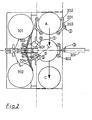
- Another characteristic of this machine lies in the fact that the positions A, B, C, successive of each rim on the conveyor, are in the same plane perpendicular to the axis of rotation of the rims.
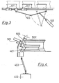
- Figures 2 and 3 show that the waiting positions (A), working (B), ejection (C) of the rims are in the same plane perpendicular to the axis of rotation of the rims.
- the movement of the rims on a conveyor is carried out by means of hooks 101, retractable at the rear and controlled in translation, on a guide rail, by a jack 102 and a toggle joint 103.
- the device for separating and placing the rims (2) comprises separators constituted by at least one bracket carrying at the end of each of its arms 201 a roller 202. By turning on a pivot 203, the separators release a rim between their rollers and let it pass from position A to position B.
- the support device (3) consists of a jack 301 whose rod controls by its free end two rollers 302 which position the rim so that its center is located in a plane perpendicular to its plane of symmetry, said plane perpendicular containing two axes, the axis of said cylinder 301 and the axis YY common to a centering tip 802 and to a cylinder 805 for introducing a valve, the function of this device being to press the rim against a roller 401 which drives it in rotation.
- the rotary drive device (4) is constituted by said roller 401 driven by a motor 402 by means of a universal joint 403.
- the roller 401 is set in rotation by the motor 402 from the start of the thrust exerted on the rim by the jack 301 by means of the rollers 302 so as to facilitate centering of the rim.
- the valve hole detection device (5) consists of a detection cell 502 controlled by a jack 501.
- the emitting part of the cell is separated from the detecting part by a support roller 503 on the edge of the rim .
- This device has the function of. detecting the valve hole, when it passes through the insertion of the optical beam, shown diagrammatically by the axis ZZ inclined at the angle (d), the restoration of which controls the positioning device (6).
- the device for positioning (6) the valve hole on the YY axis is constituted by a roller 601 driven in slow rotation, as soon as the detection of the hole is made, until said hole is placed on the YY axis. .
- This roller 601 measures the angle of rotation of the rim between the detection (5) and the positioning (6).
- the detection (5) and positioning (6) devices are located in different planes, they are mechanically independent in their movements.
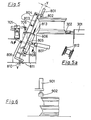
- the device for selecting a valve (7) for each rim consists of at least one vibrating bowl 701, 702 supplied with valves, at least one rail 703, 704 leading the valves to a selection manipulator 705 which places each valve in a gripper 706 for taking charge which introduces it onto the finger 813 of the introduction jack 805.
- the jack 801 provided with a finger 802 for centering and the jack 805 carrying a valve to be placed in its location on the rim are arranged on the support 809 so that these three elements are on the same axis YY.
- the support 809 comprises a support roller 803 rotatably mounted on two compensating springs 804, said roller being disposed on the support so that the outer rim of the rim is supported thereon during its rotation and during the phase of introduction of the valve.
- the fulcrum of the actuator 805 for introducing the valve is a hinge 808.
- the support 809 also includes a cradle 806 for positioning the actuator 805 and a recentering support 812 determining the position in which the axis of the introduction cylinder coincides with the YY axis.
- a double-acting cylinder 807 is supported on the frame to alternately move the introduction cylinder 805 sometimes towards the clamp 706 for taking charge of a valve, sometimes towards the centering support 812 through the support 809.
- Locking 811 immobilizes the support 809 on the ball 810 when said support makes an angle (d) with the normal to the plane of symmetry of the rim so that the jack can put the valve in place.
- the support device (9) consists of a jack 901 acting on a pad 902 so that the rim is held to resist the thrust of the device for placing the valve (8).
- the actuation of the device for introducing a valve (8) takes place when the hole is detected by the cell 502.
- the support 809 of the device (8) moved by the action of the displacement cylinder 807 passes through 'A position perpendicular to the plane of symmetry of the rim, at a position making an angle (d) with said plane, thus coming to bear on the cradle 806 and in alignment with the refocusing needle 802.
- the needle 802 driven by the recentering cylinder 801, is introduced into the valve hole which has the effect of aligning on the same axis, YY passing through the center of the valve hole and making an angle (d) with the plane perpendicular to the plane of symmetry of the rim, the insertion finger 813 and the needle 802.
- valve hole of the rim being thus centered, the locking 81 of the ball joint 810 immobilizes the support 809, which authorizes the withdrawal of the centering finger 802, outside the valve hole.
- the valve introduction cylinder 805 duly provided with a valve sprinkled with soapy water, puts it in the valve hole of the rim.
- a correct placement check can be added.
- the support rollers 302 are withdrawn and the rim is unbridled.
- the rim is transferred from the working position B to the ejection position and simultaneously another rim moves from the standby position A to the position B.
- the support 809 moves back and is placed in 812 centering support.
- the cylinder 805 represents the vertical position by pivoting on its articulation 808 to wait in this position for the start of the arriving cycle.
- valve is the presence of a rim on the separators, in position A, which will trigger the cycle.
- the clamp 706 grasps the valve, returns to its central position and places this valve on the introduction finger 813.
Landscapes
- Engineering & Computer Science (AREA)
- Mechanical Engineering (AREA)
- Automatic Assembly (AREA)
- Manipulator (AREA)
Applications Claiming Priority (2)
| Application Number | Priority Date | Filing Date | Title |
|---|---|---|---|
| FR7914243A FR2457779A1 (fr) | 1979-05-28 | 1979-05-28 | Machine pour la mise en place de valves sur des jantes pour pneus sans chambre |
| FR7914243 | 1979-05-28 |
Publications (2)
| Publication Number | Publication Date |
|---|---|
| EP0019981A1 EP0019981A1 (fr) | 1980-12-10 |
| EP0019981B1 true EP0019981B1 (fr) | 1983-11-02 |
Family
ID=9226192
Family Applications (1)
| Application Number | Title | Priority Date | Filing Date |
|---|---|---|---|
| EP19800200498 Expired EP0019981B1 (fr) | 1979-05-28 | 1980-05-24 | Machine pour la mise en place de valves sur des jantes pour pneus sans chambre |
Country Status (4)
| Country | Link |
|---|---|
| EP (1) | EP0019981B1 (OSRAM) |
| DE (1) | DE3065448D1 (OSRAM) |
| ES (1) | ES8102016A1 (OSRAM) |
| FR (1) | FR2457779A1 (OSRAM) |
Cited By (1)
| Publication number | Priority date | Publication date | Assignee | Title |
|---|---|---|---|---|
| DE102005058746A1 (de) * | 2005-11-21 | 2007-06-06 | Kia Motors Corporation | Vorrichtung und Verfahren zum Zusammenbau eines Fahrzeugrades |
Families Citing this family (1)
| Publication number | Priority date | Publication date | Assignee | Title |
|---|---|---|---|---|
| JP3558396B2 (ja) * | 1995-01-06 | 2004-08-25 | 富士重工業株式会社 | チューブレスタイヤ用タイヤバルブ自動挿入装置 |
Family Cites Families (2)
| Publication number | Priority date | Publication date | Assignee | Title |
|---|---|---|---|---|
| US2900709A (en) * | 1956-01-10 | 1959-08-25 | Allied Steel And Conveyors Inc | Automatic valve stem inserter |
| FR1365291A (fr) * | 1962-12-19 | 1964-07-03 | Hymatic Eng Co Ltd | Appareil pour fixer les valves sur les jantes de roues comportant des pneumatiques sans chambre à air |
-
1979
- 1979-05-28 FR FR7914243A patent/FR2457779A1/fr active Granted
-
1980
- 1980-05-24 EP EP19800200498 patent/EP0019981B1/fr not_active Expired
- 1980-05-24 DE DE8080200498T patent/DE3065448D1/de not_active Expired
- 1980-05-28 ES ES491924A patent/ES8102016A1/es not_active Expired
Cited By (1)
| Publication number | Priority date | Publication date | Assignee | Title |
|---|---|---|---|---|
| DE102005058746A1 (de) * | 2005-11-21 | 2007-06-06 | Kia Motors Corporation | Vorrichtung und Verfahren zum Zusammenbau eines Fahrzeugrades |
Also Published As
| Publication number | Publication date |
|---|---|
| ES491924A0 (es) | 1980-12-16 |
| DE3065448D1 (en) | 1983-12-08 |
| FR2457779A1 (fr) | 1980-12-26 |
| FR2457779B1 (OSRAM) | 1982-09-17 |
| EP0019981A1 (fr) | 1980-12-10 |
| ES8102016A1 (es) | 1980-12-16 |
Similar Documents
| Publication | Publication Date | Title |
|---|---|---|
| CN104609348B (zh) | 一种用于样本容器的自动开盖装置 | |
| FR2711125A1 (fr) | Chargeur pour machine d'impression pour objets présentés en pile. | |
| FR2526770A1 (fr) | Dispositif pour prelever et redeposer des pieces de tissu empilees | |
| WO2014090753A1 (fr) | Dispositif de ponçage comprenant des moyens de changement de disque abrasif | |
| FR2733709A1 (fr) | Ameliorations concernant le calibrage du diametre de parties cylindriques excentrees de pieces a usiner | |
| EP0052045A1 (fr) | Machine automatique à capsuler et étiqueter les bouteilles ou contenants analogues | |
| EP0019981B1 (fr) | Machine pour la mise en place de valves sur des jantes pour pneus sans chambre | |
| CN115592173A (zh) | 一种刹车盘找平衡专用机床及其使用方法 | |
| KR910005129B1 (ko) | 타이어수리장치 | |
| FR2646114A1 (fr) | Procede et dispositif pour le rivetage d'un bandage aux sommets d'ailettes montees sur un rotor | |
| JPH03166169A (ja) | スライバケンスにおけるスライバ端部を固定するための方法及び装置 | |
| CN222063312U (zh) | 一种换盒翻转机 | |
| CH303485A (fr) | Machine à étiqueter des articles tels que bouteilles, boîtes en fer-blanc, paquets et objets similaires. | |
| FR2511500A1 (fr) | Systeme d'alignement de roue et de pneu | |
| CH467176A (fr) | Dispositif pour détacher les talons de pneus d'une jante de roue | |
| IE31949L (en) | Tyre fitting and removal apparatus | |
| CN109848702A (zh) | 钢水取样器自动装配装置 | |
| FR2660638A1 (fr) | Dispositif pour la prehension de produits souples et minces et pour leur extraction d'un ensemble de tels produits. | |
| JPS6339441B2 (OSRAM) | ||
| FR2499958A1 (fr) | Perfectionnements aux machines a enrouler des bandes de matiere en bobines | |
| JPS5816992Y2 (ja) | 空壜検査機における除壜装置 | |
| JPH09123717A (ja) | タイヤ着脱装置 | |
| JP3588810B2 (ja) | エンジンバルブのフェース振れ検査機 | |
| JPS643628Y2 (OSRAM) | ||
| GB1532264A (en) | Apparatus for pneumatically separating a foot lap from a spinning cop |
Legal Events
| Date | Code | Title | Description |
|---|---|---|---|
| PUAI | Public reference made under article 153(3) epc to a published international application that has entered the european phase |
Free format text: ORIGINAL CODE: 0009012 |
|
| AK | Designated contracting states |
Designated state(s): DE GB IT SE |
|
| 17P | Request for examination filed |
Effective date: 19810313 |
|
| ITF | It: translation for a ep patent filed | ||
| GRAA | (expected) grant |
Free format text: ORIGINAL CODE: 0009210 |
|
| AK | Designated contracting states |
Designated state(s): DE GB IT SE |
|
| REF | Corresponds to: |
Ref document number: 3065448 Country of ref document: DE Date of ref document: 19831208 |
|
| PLBE | No opposition filed within time limit |
Free format text: ORIGINAL CODE: 0009261 |
|
| STAA | Information on the status of an ep patent application or granted ep patent |
Free format text: STATUS: NO OPPOSITION FILED WITHIN TIME LIMIT |
|
| 26N | No opposition filed | ||
| PGFP | Annual fee paid to national office [announced via postgrant information from national office to epo] |
Ref country code: DE Payment date: 19910506 Year of fee payment: 12 |
|
| PGFP | Annual fee paid to national office [announced via postgrant information from national office to epo] |
Ref country code: GB Payment date: 19910513 Year of fee payment: 12 |
|
| PGFP | Annual fee paid to national office [announced via postgrant information from national office to epo] |
Ref country code: SE Payment date: 19910521 Year of fee payment: 12 |
|
| ITTA | It: last paid annual fee | ||
| PG25 | Lapsed in a contracting state [announced via postgrant information from national office to epo] |
Ref country code: GB Effective date: 19920524 |
|
| PG25 | Lapsed in a contracting state [announced via postgrant information from national office to epo] |
Ref country code: SE Effective date: 19920525 |
|
| GBPC | Gb: european patent ceased through non-payment of renewal fee |
Effective date: 19920524 |
|
| PG25 | Lapsed in a contracting state [announced via postgrant information from national office to epo] |
Ref country code: DE Effective date: 19930202 |
|
| EUG | Se: european patent has lapsed |
Ref document number: 80200498.6 Effective date: 19921204 |