EP0019933A1 - Temperature controlled unit injector - Google Patents
Temperature controlled unit injector Download PDFInfo
- Publication number
- EP0019933A1 EP0019933A1 EP80103060A EP80103060A EP0019933A1 EP 0019933 A1 EP0019933 A1 EP 0019933A1 EP 80103060 A EP80103060 A EP 80103060A EP 80103060 A EP80103060 A EP 80103060A EP 0019933 A1 EP0019933 A1 EP 0019933A1
- Authority
- EP
- European Patent Office
- Prior art keywords
- nozzle end
- fluid
- retainer
- circumferential groove
- groove
- Prior art date
- Legal status (The legal status is an assumption and is not a legal conclusion. Google has not performed a legal analysis and makes no representation as to the accuracy of the status listed.)
- Granted
Links
Images


Classifications
-
- F—MECHANICAL ENGINEERING; LIGHTING; HEATING; WEAPONS; BLASTING
- F02—COMBUSTION ENGINES; HOT-GAS OR COMBUSTION-PRODUCT ENGINE PLANTS
- F02M—SUPPLYING COMBUSTION ENGINES IN GENERAL WITH COMBUSTIBLE MIXTURES OR CONSTITUENTS THEREOF
- F02M53/00—Fuel-injection apparatus characterised by having heating, cooling or thermally-insulating means
- F02M53/04—Injectors with heating, cooling, or thermally-insulating means
- F02M53/043—Injectors with heating, cooling, or thermally-insulating means with cooling means other than air cooling
-
- F—MECHANICAL ENGINEERING; LIGHTING; HEATING; WEAPONS; BLASTING
- F02—COMBUSTION ENGINES; HOT-GAS OR COMBUSTION-PRODUCT ENGINE PLANTS
- F02M—SUPPLYING COMBUSTION ENGINES IN GENERAL WITH COMBUSTIBLE MIXTURES OR CONSTITUENTS THEREOF
- F02M53/00—Fuel-injection apparatus characterised by having heating, cooling or thermally-insulating means
-
- F—MECHANICAL ENGINEERING; LIGHTING; HEATING; WEAPONS; BLASTING
- F02—COMBUSTION ENGINES; HOT-GAS OR COMBUSTION-PRODUCT ENGINE PLANTS
- F02M—SUPPLYING COMBUSTION ENGINES IN GENERAL WITH COMBUSTIBLE MIXTURES OR CONSTITUENTS THEREOF
- F02M57/00—Fuel-injectors combined or associated with other devices
- F02M57/02—Injectors structurally combined with fuel-injection pumps
-
- F—MECHANICAL ENGINEERING; LIGHTING; HEATING; WEAPONS; BLASTING
- F02—COMBUSTION ENGINES; HOT-GAS OR COMBUSTION-PRODUCT ENGINE PLANTS
- F02D—CONTROLLING COMBUSTION ENGINES
- F02D2200/00—Input parameters for engine control
- F02D2200/02—Input parameters for engine control the parameters being related to the engine
- F02D2200/06—Fuel or fuel supply system parameters
- F02D2200/0606—Fuel temperature
Definitions
- This invention relates generally to internal combustion engines and more particularly to temperature control in oil engines having forced oil supply.
- the nozzle or tip end of a unit fuel injection device is adjacent the combustion area of a cylinder and is therefore exposed to operate in a high temperature environment.
- Temperature control of the tip or nozzle end usually involves the use of fluids and maintaining control is advantageous to assure proper functioning of the fuel injector.
- One problem in providing proper temperature control is moving a sufficient amount of fluid to assure adequate temperature control. Obviously, the greater the volume of fluid moved, the greater the temperature controlling effect.
- a temperature controlled unit fuel injector including a retainer sleeve having a nozzle end and means for conducting fluid toward and away from the nozzle end. Fluid is conducted into a circumferential groove cooperating with an axial passage for moving fluid adjacent the nozzle end of the fuel injector.
- the circumferential groove and the axial passage are formed in the outer peripheral surface of the retainer.
- a portion of a fuel injection system is graphically represented including an engine 10 having one of several unit injectors 12 mounted therein adjacent a respective cylinder (not shown) of engine 10.
- a tank 14 supplies fluid such as fuel to a transfer pump 16 via an appropriate conduit 18.
- Pump 16 supplies fuel to fuel injector 12 at a substantially low pressure.
- Some of the fuel from pump 16 is directed, via conduit 20, to fuel injector 12 to be injected into the respective cylinder.
- Other of the fuel from pump 16 is directed to fuel injector 12, via concuit 22, as a temperature controlling fluid, in this instance for cooling injector 12.
- the cooling fuel is then directed from injector 12 back to tank 14 via conduit 24 for further cooling substantially to ambient temperature and the cycle is repeated.
- optional flow restrictors 26 may be used in either or both conduits 20,22 to control the fuel flow between pump 16 and injector 12.
- a medium other than fuel may be used for cooling; however, such would require an additional tank, pump and additional conduits.
- An element such as a heat exchanger 28 may be used to supplement cooling.
- Figure 2 graphically illustrates that a fluid may be supplied to heat the fuel injector 112 in some instances.
- a system is anticipated including an engine 110 having one of several unit fuel injectors 112 mounted therein adjacent a respective cylinder (not shown) of engine 110.
- Such an engine may use a thicker, less viscous residual type fuel stored in tank 114.
- Such fuels could be heated by a supplemental element such as a heat exchanger 128 to thin or reduce the viscosity of the fuel.
- the fuel could then be supplied to injector 112 by pump 116. In this situation cooling of the tip is of increased importance.
- a separate fluid could be stored in tank 214, cooled by a heat exchanger 228 and supplied to injector 112 by an alternate pump 216.
- This separate fluid could be conventional fuel or some other fluid and could be used to supply cooling or in some instances to supply heat to injector 112 by some arrangement such as, for example, injecting steam into heat exchanger 228, on command, by actuating a valve 230. Presence of a heated fluid in injector 112 could avoid congealing of the residual fuel in the event of a rapid shutdown of engine 110 occurring without an opportunity to purge the unit injector of high viscosity fuel prior to shutdown.
- a cylinder head 32 includes well known cooling passages 34 which are formed in the head.
- a unit injector 12 is seated in head 32 including a nozzle end 36 terminating at a tip 38 adjacent a cylinder (not shown).
- Means are provided for conducting temperature controlling fluid, whether heated or cooled, toward and away from nozzle end 36.
- a portion of such means includes, but is not limited to, a circumferential groove 52 and an axial passage 54 formed in outer peripheral surface 56 of retainer sleeve 48 by machining or the like. It is preferred that axial passage 54 include two inlet passages 54a,b and two outlet passages 54c,d (best shown in Fig. 4).
- Groove 52 is positioned to be aligned with inlet-outlet ports 58 (Fig. 4 also) formed in head 32 when tapered abutment 61 of sleeve 48 contacts tapered seat 63.
- Either of the ports 58 can be an inlet or outlet for a temperature controlling fluid depending on a desired direction of flow.
- the inlet will be designated 58a and the outlet will be designated 58b.
- Another portion of the means for conducting temperature controlling fluid toward nozzle end 36 includes passages formed in tip assembly 46, described as follows: the inlet passages 54a,b extend from groove 52 to tip inlet annulus 74 via two respective temperature control inlet bores 76 (only one shown) and then to tip temperature control annulus 78 via two tip inlet passages 80 (only one shown). Temperature controlling fluid in tip temperature control annulus 78 is then communicated to tip outlet annulus 82 via two tip outlet passages 84 (only one shown). From annulus 82, temperature control fluid is communicated to outlet passages 54c,d via two respective temperature control outlet bores 86 (only one shown).
- Means are provided for limiting leakage of temperature controlling fluid from passage 43.
- Such means comprises axial sealing grooves formed in outer periphery 56 of retainer 48 and are substantially parallel with the axial passage 54 (see Fig. 5).
- sealing grooves 90 preferably extend from circumferential groove 52 to chamfer 92.
- passages 54a,b are each situated between a pair of such sealing grooves 90 as illustrated in Figs. 4 and 5.
- a sealing member 94 resistant to fuel contamination, such as one formed of a fluorocarbon rubber, is provided in each groove 90 to seat against sleeve bore 50 of head 32. Clearance between sleeve 48 and bore 50 is approximately .008 inches and even without seals 94 only 10% of fuel in passages 54a,b was found to bypass to passages 54c,d. However, seals 94 are preferred.
- Means are provided for separating one portion 52a of groove 52 from another portion 52b.
- Such means comprise sealing plugs 96 preferably formed of a fluorocarbon rubber, impervious to deterioration due to fuel contamination, and being squeeze or force fitted into groove 52 to seat against bore 50 and limit mingling of fluid in portion 52a with fluid in portion 52b.
- Temperature controlling fluid is conducted through head 32 via inlet 58a to inlet portion 52a of groove 52 guarded by sealing plugs 96.
- Inlet fluid is then conducted via two axial passages 54a,b toward nozzle end 36 and then through two inlet bores 76 to annulus 74.
- Two other inlet passages connect annulus 74 with tip annulus 78.
- Fluid is carried away from annulus 78 via two outlet passages 84 to outlet annulus 82. From there the fluid is routed through two outlet bores 86, two axial outlet passages 54c,d and then confined to outlet portion 52b of groove 52 due to sealing plugs 96.
- the fluid then exits injector 12 through outlet 58b formed in head 32.
- a temperature controlled unit fuel injector including a retainer sleeve having a nozzle end and means for moving temperature controlling fluid toward and away from the nozzle end. Increased volumes of temperature controlling fluid are provided to the nozzle end without the need to enlarge the size of the unit fuel injector.
Abstract
Description
- This invention relates generally to internal combustion engines and more particularly to temperature control in oil engines having forced oil supply.
- The nozzle or tip end of a unit fuel injection device is adjacent the combustion area of a cylinder and is therefore exposed to operate in a high temperature environment. Temperature control of the tip or nozzle end usually involves the use of fluids and maintaining control is advantageous to assure proper functioning of the fuel injector. One problem in providing proper temperature control is moving a sufficient amount of fluid to assure adequate temperature control. Obviously, the greater the volume of fluid moved, the greater the temperature controlling effect.
- Supplying a greater volume of fluid involves enlarged fluid passageways. These passageways are usually provided in the various parts of a unit injector housed in a retainer sleeve. During assembly of these parts, time-consuming care must be taken to properly align the passageways. Enlarged passageways require additional space which results in a need to enlarge the unit injector and, since space is critically limited, it is difficult to provide adequately enlarged passageways.
- In view of the above, it would be advantageous to provide a unit injector which provides adequate temperature control, avoids excessive use of critical space, avoids time-consuming assembly problems, and which overcomes the problems associated with the prior art.
- In one aspect of the present invention, the problems pertaining to the known prior art, as set forth above, are advantageously avoided.
- This is accomplished by providing a temperature controlled unit fuel injector including a retainer sleeve having a nozzle end and means for conducting fluid toward and away from the nozzle end. Fluid is conducted into a circumferential groove cooperating with an axial passage for moving fluid adjacent the nozzle end of the fuel injector. The circumferential groove and the axial passage are formed in the outer peripheral surface of the retainer.
- The foregoing and other advantages will become apparent from the following detailed description of the invention when considered in conjunction with the accompanying drawings. It is to be expressly understood, however, that the drawings are not intended as a definition of the invention but are for the purpose of illustration only.
- In the drawings:
- FIGURE 1 is a graphic view illustrating a portion of a fuel injection system;
- FIGURE 2 is a graphic view illustrating a portion of an alternative fuel injection system;
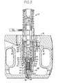
- FIGURE 3 is a cross-sectional view illustrating an embodiment of the present invention;
- FIGURE 4 is a cross-sectional view taken along line IV-IV of Figure 3 and illustrating the circumferential groove including separating plugs; and
- FIGURE 5 is a side elevation generally illustrating the present invention.
- Referring now to Figure 1, a portion of a fuel injection system is graphically represented including an
engine 10 having one ofseveral unit injectors 12 mounted therein adjacent a respective cylinder (not shown) ofengine 10. To establish a reference cycle, atank 14 supplies fluid such as fuel to a transfer pump 16 via anappropriate conduit 18. Pump 16 supplies fuel tofuel injector 12 at a substantially low pressure. - Some of the fuel from pump 16 is directed, via
conduit 20, tofuel injector 12 to be injected into the respective cylinder. Other of the fuel from pump 16 is directed tofuel injector 12, viaconcuit 22, as a temperature controlling fluid, in this instance forcooling injector 12. The cooling fuel is then directed frominjector 12 back totank 14 viaconduit 24 for further cooling substantially to ambient temperature and the cycle is repeated. - If the output of pump 16 is at too great a rate,
optional flow restrictors 26 may be used in either or bothconduits injector 12. - A medium other than fuel may be used for cooling; however, such would require an additional tank, pump and additional conduits. An element such as a
heat exchanger 28 may be used to supplement cooling. - As an alternative, Figure 2 graphically illustrates that a fluid may be supplied to heat the fuel injector 112 in some instances. A system is anticipated including an
engine 110 having one of several unit fuel injectors 112 mounted therein adjacent a respective cylinder (not shown) ofengine 110. Such an engine may use a thicker, less viscous residual type fuel stored intank 114. Such fuels could be heated by a supplemental element such as aheat exchanger 128 to thin or reduce the viscosity of the fuel. The fuel could then be supplied to injector 112 bypump 116. In this situation cooling of the tip is of increased importance. - A separate fluid could be stored in
tank 214, cooled by aheat exchanger 228 and supplied to injector 112 by analternate pump 216. This separate fluid could be conventional fuel or some other fluid and could be used to supply cooling or in some instances to supply heat to injector 112 by some arrangement such as, for example, injecting steam intoheat exchanger 228, on command, by actuating a valve 230. Presence of a heated fluid in injector 112 could avoid congealing of the residual fuel in the event of a rapid shutdown ofengine 110 occurring without an opportunity to purge the unit injector of high viscosity fuel prior to shutdown. - In Figure 3, a
cylinder head 32 includes well knowncooling passages 34 which are formed in the head. Aunit injector 12 is seated inhead 32 including anozzle end 36 terminating at atip 38 adjacent a cylinder (not shown). - Well known elements of
fuel injector 12, such asplunger 39,barrel 40,spring cage 42,lift stop 44 andtip assembly 46, to name a few, are housed in a "retainer"sleeve 48 seated inhead 32 atsleeve bore 50. Also, as it is known, means are provided inhead 32 for conducting injection fluid to tip 38 ofnozzle end 36. Such means includes supply ports 60 (Fig. 4 also),annular groove 62, filteredinlets 64, port 66,bore 68 andnozzle bore 70. Groove 62 is positioned to be aligned with ports 60 when taperedabutment 61 ofsleeve 48 contacts taperedseat 63. - Means are provided for conducting temperature controlling fluid, whether heated or cooled, toward and away from
nozzle end 36. A portion of such means includes, but is not limited to, acircumferential groove 52 and anaxial passage 54 formed in outerperipheral surface 56 ofretainer sleeve 48 by machining or the like. It is preferred thataxial passage 54 include twoinlet passages 54a,b and twooutlet passages 54c,d (best shown in Fig. 4). - Groove 52 is positioned to be aligned with inlet-outlet ports 58 (Fig. 4 also) formed in
head 32 when taperedabutment 61 ofsleeve 48 contacts taperedseat 63. Either of the ports 58 can be an inlet or outlet for a temperature controlling fluid depending on a desired direction of flow. For purposes of this discussion, the inlet will be designated 58a and the outlet will be designated 58b. - Another portion of the means for conducting temperature controlling fluid toward
nozzle end 36 includes passages formed intip assembly 46, described as follows: theinlet passages 54a,b extend fromgroove 52 to tipinlet annulus 74 via two respective temperature control inlet bores 76 (only one shown) and then to tiptemperature control annulus 78 via two tip inlet passages 80 (only one shown). Temperature controlling fluid in tiptemperature control annulus 78 is then communicated to tipoutlet annulus 82 via two tip outlet passages 84 (only one shown). Fromannulus 82, temperature control fluid is communicated tooutlet passages 54c,d via two respective temperature control outlet bores 86 (only one shown). - The use of two of each of the above-described temperature controlling fluid passages permits additional fluid volume to be moved through the
injector 12. Single, enlarged passages could be formed as axial bores throughretainer sleeve 48 but would require enlarging the overall size of theinjector 12. Forming theaxial passage 54 in theouter periphery 56 ofretainer sleeve 48permits sleeve 48 to handle added volume of temperature controlling fluid without the need to increase the size ofretainer 48 such as by increased wall thickness. - Means are provided for limiting leakage of temperature controlling fluid from passage 43. Such means comprises axial sealing grooves formed in
outer periphery 56 ofretainer 48 and are substantially parallel with the axial passage 54 (see Fig. 5). It will be noted that sealinggrooves 90 preferably extend fromcircumferential groove 52 to chamfer 92. Ideally,passages 54a,b are each situated between a pair ofsuch sealing grooves 90 as illustrated in Figs. 4 and 5. A sealingmember 94, resistant to fuel contamination, such as one formed of a fluorocarbon rubber, is provided in eachgroove 90 to seat against sleeve bore 50 ofhead 32. Clearance betweensleeve 48 and bore 50 is approximately .008 inches and even withoutseals 94 only 10% of fuel inpassages 54a,b was found to bypass topassages 54c,d. However, seals 94 are preferred. - Means are provided for separating one
portion 52a ofgroove 52 from anotherportion 52b. Such means comprise sealingplugs 96 preferably formed of a fluorocarbon rubber, impervious to deterioration due to fuel contamination, and being squeeze or force fitted intogroove 52 to seat against bore 50 and limit mingling of fluid inportion 52a with fluid inportion 52b. - Temperature controlling fluid, either heated or cooled as above described, is conducted through
head 32 viainlet 58a toinlet portion 52a ofgroove 52 guarded by sealingplugs 96. Inlet fluid is then conducted via twoaxial passages 54a,b towardnozzle end 36 and then through two inlet bores 76 toannulus 74. Two other inlet passages connectannulus 74 withtip annulus 78. Fluid is carried away fromannulus 78 via twooutlet passages 84 tooutlet annulus 82. From there the fluid is routed through two outlet bores 86, twoaxial outlet passages 54c,d and then confined tooutlet portion 52b ofgroove 52 due to sealing plugs 96. The fluid then exitsinjector 12 throughoutlet 58b formed inhead 32. - The foregoing has described a temperature controlled unit fuel injector including a retainer sleeve having a nozzle end and means for moving temperature controlling fluid toward and away from the nozzle end. Increased volumes of temperature controlling fluid are provided to the nozzle end without the need to enlarge the size of the unit fuel injector.
Claims (10)
Applications Claiming Priority (2)
| Application Number | Priority Date | Filing Date | Title |
|---|---|---|---|
| US06/085,341 US4267977A (en) | 1979-06-04 | 1979-06-04 | Temperature controlled unit injector |
| WOPCT/US79/00382 | 1979-06-04 |
Publications (2)
| Publication Number | Publication Date |
|---|---|
| EP0019933A1 true EP0019933A1 (en) | 1980-12-10 |
| EP0019933B1 EP0019933B1 (en) | 1983-05-18 |
Family
ID=22190959
Family Applications (1)
| Application Number | Title | Priority Date | Filing Date |
|---|---|---|---|
| EP80103060A Expired EP0019933B1 (en) | 1979-06-04 | 1980-06-02 | Temperature controlled unit injector |
Country Status (5)
| Country | Link |
|---|---|
| US (1) | US4267977A (en) |
| EP (1) | EP0019933B1 (en) |
| JP (1) | JPS6014907B2 (en) |
| CA (1) | CA1127484A (en) |
| WO (1) | WO1980002654A1 (en) |
Cited By (1)
| Publication number | Priority date | Publication date | Assignee | Title |
|---|---|---|---|---|
| FR2663372A1 (en) * | 1990-06-19 | 1991-12-20 | Renault | Device for cooling the injectors of an engine |
Families Citing this family (14)
| Publication number | Priority date | Publication date | Assignee | Title |
|---|---|---|---|---|
| US5010783A (en) * | 1990-07-02 | 1991-04-30 | Caterpillar Inc. | Tappet retainer assembly |
| DE4227853C2 (en) * | 1992-08-22 | 1996-05-30 | Bosch Gmbh Robert | Fuel injection pump for internal combustion engines |
| JP3228497B2 (en) * | 1996-03-27 | 2001-11-12 | 株式会社豊田中央研究所 | Fuel injection valve deposit reduction method and deposit reduction type fuel injection valve |
| US6905672B2 (en) * | 1999-12-08 | 2005-06-14 | The Procter & Gamble Company | Compositions and methods to inhibit tartar and microbes using denture adhesive compositions with colorants |
| US6446612B1 (en) | 2000-10-25 | 2002-09-10 | James Dwayne Hankins | Fuel injection system, components therefor and methods of making the same |
| DE10259926A1 (en) * | 2002-12-20 | 2004-07-01 | Robert Bosch Gmbh | Internal combustion engine |
| AT500773B8 (en) * | 2004-08-24 | 2007-02-15 | Bosch Gmbh Robert | INJECTION NOZZLE FOR INTERNAL COMBUSTION ENGINES |
| US8517284B2 (en) | 2009-05-13 | 2013-08-27 | Caterpillar Inc. | System and method for internal cooling of a fuel injector |
| US8434457B2 (en) * | 2010-06-29 | 2013-05-07 | Caterpillar Inc. | System and method for cooling fuel injectors |
| US8371254B2 (en) | 2010-08-04 | 2013-02-12 | Ford Global Technologies, Llc | Fuel injector cooling |
| US8474251B2 (en) | 2010-10-19 | 2013-07-02 | Ford Global Technologies, Llc | Cylinder head cooling system |
| US8814171B2 (en) | 2011-10-25 | 2014-08-26 | Ford Global Technologies, Llc | Engine sealing assembly |
| JP5831510B2 (en) * | 2012-11-20 | 2015-12-09 | 株式会社デンソー | Fuel injection valve and fuel injection valve mounting method |
| US10605213B2 (en) * | 2015-08-21 | 2020-03-31 | Cummins Inc. | Nozzle combustion shield and sealing member with improved heat transfer capabilities |
Citations (13)
| Publication number | Priority date | Publication date | Assignee | Title |
|---|---|---|---|---|
| DE486667C (en) * | 1927-04-22 | 1929-11-27 | Oskar Gnauck | Fuel injection device for diesel engines with pressure atomization |
| US1879985A (en) * | 1928-04-13 | 1932-09-27 | Motorenfabrik Deutz Ag | Cooled nozzle for fuel valves in internal combustion engines |
| FR763137A (en) * | 1934-04-23 | |||
| US2096711A (en) * | 1934-11-28 | 1937-10-26 | Gen Motors Corp | Fuel pump for injectors |
| GB503432A (en) * | 1937-10-27 | 1939-04-06 | Bryce Ltd | Improvements relating to fuel injectors of internal combustion engines |
| DE846635C (en) * | 1950-05-13 | 1952-08-14 | Kloeckner Humboldt Deutz Ag | Fuel injector |
| FR1189684A (en) * | 1957-01-23 | 1959-10-06 | Maschf Augsburg Nuernberg Ag | Device for cooling the jets of internal combustion engines |
| FR1207506A (en) * | 1958-06-23 | 1960-02-17 | Method, device and installation for fuel injection for internal combustion engines | |
| CH432934A (en) * | 1965-07-10 | 1967-03-31 | Maschf Augsburg Nuernberg Ag | Device for operating an internal combustion engine with fuel of higher viscosity |
| US3398895A (en) * | 1966-03-30 | 1968-08-27 | Bosch Arma Corp | Cooled fuel injection nozzle |
| US3460760A (en) * | 1967-06-15 | 1969-08-12 | Gen Motors Corp | Fuel injection nozzle assembly |
| US3737100A (en) * | 1971-11-18 | 1973-06-05 | Allis Chalmers | Internally cooled unit injector |
| FR2313571A1 (en) * | 1975-06-04 | 1976-12-31 | Ckd Praha | Cooling system for diesel engine injection nozzles - includes control throttle operated by engine to regulate fluid flow |
Family Cites Families (7)
| Publication number | Priority date | Publication date | Assignee | Title |
|---|---|---|---|---|
| US1333612A (en) * | 1918-12-02 | 1920-03-16 | Joseph O Fisher | Apparatus for injecting fuel into combustion-chambers |
| US1885004A (en) * | 1930-05-21 | 1932-10-25 | Allen T Crumbaker | Injection nozzle |
| US1860063A (en) * | 1930-09-25 | 1932-05-24 | Sulzer Ag | Fuel injection device for internal combustion engines |
| US2425229A (en) * | 1940-10-11 | 1947-08-05 | Bendix Aviat Corp | Fuel injection apparatus |
| US2556356A (en) * | 1946-04-26 | 1951-06-12 | American Bosch Corp | Accumulator type injector nozzle |
| GB720916A (en) * | 1952-05-03 | 1954-12-29 | Sulzer Ag | Fuel injectors for internal combustion engines |
| DE2137030A1 (en) * | 1971-07-23 | 1973-02-01 | Werner Dipl Phys Kraus | FUEL INJECTION DEVICE |
-
1979
- 1979-06-04 JP JP54501870A patent/JPS6014907B2/en not_active Expired
- 1979-06-04 US US06/085,341 patent/US4267977A/en not_active Expired - Lifetime
- 1979-06-04 WO PCT/US1979/000382 patent/WO1980002654A1/en unknown
-
1980
- 1980-02-27 CA CA346,577A patent/CA1127484A/en not_active Expired
- 1980-06-02 EP EP80103060A patent/EP0019933B1/en not_active Expired
Patent Citations (13)
| Publication number | Priority date | Publication date | Assignee | Title |
|---|---|---|---|---|
| FR763137A (en) * | 1934-04-23 | |||
| DE486667C (en) * | 1927-04-22 | 1929-11-27 | Oskar Gnauck | Fuel injection device for diesel engines with pressure atomization |
| US1879985A (en) * | 1928-04-13 | 1932-09-27 | Motorenfabrik Deutz Ag | Cooled nozzle for fuel valves in internal combustion engines |
| US2096711A (en) * | 1934-11-28 | 1937-10-26 | Gen Motors Corp | Fuel pump for injectors |
| GB503432A (en) * | 1937-10-27 | 1939-04-06 | Bryce Ltd | Improvements relating to fuel injectors of internal combustion engines |
| DE846635C (en) * | 1950-05-13 | 1952-08-14 | Kloeckner Humboldt Deutz Ag | Fuel injector |
| FR1189684A (en) * | 1957-01-23 | 1959-10-06 | Maschf Augsburg Nuernberg Ag | Device for cooling the jets of internal combustion engines |
| FR1207506A (en) * | 1958-06-23 | 1960-02-17 | Method, device and installation for fuel injection for internal combustion engines | |
| CH432934A (en) * | 1965-07-10 | 1967-03-31 | Maschf Augsburg Nuernberg Ag | Device for operating an internal combustion engine with fuel of higher viscosity |
| US3398895A (en) * | 1966-03-30 | 1968-08-27 | Bosch Arma Corp | Cooled fuel injection nozzle |
| US3460760A (en) * | 1967-06-15 | 1969-08-12 | Gen Motors Corp | Fuel injection nozzle assembly |
| US3737100A (en) * | 1971-11-18 | 1973-06-05 | Allis Chalmers | Internally cooled unit injector |
| FR2313571A1 (en) * | 1975-06-04 | 1976-12-31 | Ckd Praha | Cooling system for diesel engine injection nozzles - includes control throttle operated by engine to regulate fluid flow |
Cited By (1)
| Publication number | Priority date | Publication date | Assignee | Title |
|---|---|---|---|---|
| FR2663372A1 (en) * | 1990-06-19 | 1991-12-20 | Renault | Device for cooling the injectors of an engine |
Also Published As
| Publication number | Publication date |
|---|---|
| CA1127484A (en) | 1982-07-13 |
| WO1980002654A1 (en) | 1980-12-11 |
| EP0019933B1 (en) | 1983-05-18 |
| JPS56500618A (en) | 1981-05-07 |
| US4267977A (en) | 1981-05-19 |
| JPS6014907B2 (en) | 1985-04-16 |
Similar Documents
| Publication | Publication Date | Title |
|---|---|---|
| EP0019933B1 (en) | Temperature controlled unit injector | |
| KR100840632B1 (en) | Fuel supply installation in the form of a common-rail system of an internal combustion engine having a plurality of cylinders | |
| US6751939B2 (en) | Flow divider and ecology valve | |
| AU2014204548B2 (en) | Dual fuel system for internal combustion engine and leakage limiting seal strategy for same | |
| NO770080L (en) | PROCEDURE AND DEVICE FOR ELIMINATING FUEL LEAK DURING INJECTION, ESPECIALLY INTO THE DIESEL ENGINE INJECTION PUMP COOLING SYSTEM | |
| US9856841B2 (en) | Fuel injector | |
| DK168022B1 (en) | DEVICE FOR OPERATION OF A STAMP COMBUSTION ENGINE WITH A RELATIVE HIGH VISCOSITY FUEL | |
| US5560825A (en) | Edge filter for a high pressure hydraulic system | |
| US5832954A (en) | Check valve assembly for inhibiting Helmholtz resonance | |
| EP1790882B1 (en) | Internal combustion engine | |
| US4593655A (en) | Valve seat ring cooling apparatus | |
| JPH03249336A (en) | Check valve mechanism for preventing leakage | |
| ATE61449T1 (en) | FUEL INJECTION DEVICE FOR A DIESEL ENGINE WITH PILOT INJECTION. | |
| KR101948936B1 (en) | A fluid injection device | |
| US6279539B1 (en) | Hydraulically actuated fuel injector with cold start features | |
| US20040211394A1 (en) | Fuel return passage for an internal combustion engine | |
| US4403577A (en) | Free piston internal combustion engines | |
| US9976527B1 (en) | Fuel injector assembly having sleeve for directing fuel flow | |
| EP0995898A2 (en) | Fuel system | |
| JPH0467021B2 (en) | ||
| JP6826371B2 (en) | Hydraulic drive piston device and crosshead internal combustion engine | |
| EP0553262B1 (en) | Fuel pump | |
| GB2581156A (en) | Fuel injection system and a supply rail body thereof | |
| JPH05332217A (en) | Hydraulic drive type water injector | |
| JPS62139968A (en) | Fuel injection device for engine |
Legal Events
| Date | Code | Title | Description |
|---|---|---|---|
| PUAI | Public reference made under article 153(3) epc to a published international application that has entered the european phase |
Free format text: ORIGINAL CODE: 0009012 |
|
| 17P | Request for examination filed | ||
| AK | Designated contracting states |
Kind code of ref document: A1 Designated state(s): BE DE GB |
|
| GRAA | (expected) grant |
Free format text: ORIGINAL CODE: 0009210 |
|
| AK | Designated contracting states |
Designated state(s): BE DE GB |
|
| REF | Corresponds to: |
Ref document number: 3063287 Country of ref document: DE Date of ref document: 19830707 |
|
| PLBE | No opposition filed within time limit |
Free format text: ORIGINAL CODE: 0009261 |
|
| STAA | Information on the status of an ep patent application or granted ep patent |
Free format text: STATUS: NO OPPOSITION FILED WITHIN TIME LIMIT |
|
| 26N | No opposition filed | ||
| REG | Reference to a national code |
Ref country code: GB Ref legal event code: 732 |
|
| PGFP | Annual fee paid to national office [announced via postgrant information from national office to epo] |
Ref country code: BE Payment date: 19940530 Year of fee payment: 15 |
|
| PG25 | Lapsed in a contracting state [announced via postgrant information from national office to epo] |
Ref country code: BE Effective date: 19950630 |
|
| BERE | Be: lapsed |
Owner name: CATERPILLAR INC. Effective date: 19950630 |
|
| PGFP | Annual fee paid to national office [announced via postgrant information from national office to epo] |
Ref country code: DE Payment date: 19990225 Year of fee payment: 20 |
|
| PGFP | Annual fee paid to national office [announced via postgrant information from national office to epo] |
Ref country code: GB Payment date: 19990302 Year of fee payment: 20 |
|
| PG25 | Lapsed in a contracting state [announced via postgrant information from national office to epo] |
Ref country code: GB Free format text: LAPSE BECAUSE OF EXPIRATION OF PROTECTION Effective date: 20000601 |
|
| REG | Reference to a national code |
Ref country code: GB Ref legal event code: PE20 Effective date: 20000601 |