EP0019500B1 - Poste d'usinage en continu de rainures dans un support de câble à fibres optiques et utilisation d'un tel poste - Google Patents
Poste d'usinage en continu de rainures dans un support de câble à fibres optiques et utilisation d'un tel poste Download PDFInfo
- Publication number
- EP0019500B1 EP0019500B1 EP19800400503 EP80400503A EP0019500B1 EP 0019500 B1 EP0019500 B1 EP 0019500B1 EP 19800400503 EP19800400503 EP 19800400503 EP 80400503 A EP80400503 A EP 80400503A EP 0019500 B1 EP0019500 B1 EP 0019500B1
- Authority
- EP
- European Patent Office
- Prior art keywords
- grooves
- tooth
- unit
- carrier
- optical fibres
- Prior art date
- Legal status (The legal status is an assumption and is not a legal conclusion. Google has not performed a legal analysis and makes no representation as to the accuracy of the status listed.)
- Expired
Links
- 238000004519 manufacturing process Methods 0.000 title claims description 17
- 230000003287 optical effect Effects 0.000 title claims 8
- 239000000835 fiber Substances 0.000 claims description 13
- 238000005520 cutting process Methods 0.000 claims description 9
- 239000007787 solid Substances 0.000 claims description 6
- 238000010438 heat treatment Methods 0.000 claims description 5
- 230000000284 resting effect Effects 0.000 claims 2
- 238000003754 machining Methods 0.000 description 41
- 239000013307 optical fiber Substances 0.000 description 8
- 238000006073 displacement reaction Methods 0.000 description 7
- 238000000034 method Methods 0.000 description 5
- 238000013021 overheating Methods 0.000 description 3
- 230000000149 penetrating effect Effects 0.000 description 3
- 230000006378 damage Effects 0.000 description 2
- 239000000463 material Substances 0.000 description 2
- 229920001179 medium density polyethylene Polymers 0.000 description 2
- 239000004701 medium-density polyethylene Substances 0.000 description 2
- 239000012815 thermoplastic material Substances 0.000 description 2
- 238000011144 upstream manufacturing Methods 0.000 description 2
- 208000027418 Wounds and injury Diseases 0.000 description 1
- 238000010924 continuous production Methods 0.000 description 1
- 238000010586 diagram Methods 0.000 description 1
- 230000000694 effects Effects 0.000 description 1
- 230000008030 elimination Effects 0.000 description 1
- 238000003379 elimination reaction Methods 0.000 description 1
- 230000004927 fusion Effects 0.000 description 1
- 208000014674 injury Diseases 0.000 description 1
- 238000003801 milling Methods 0.000 description 1
- 230000035515 penetration Effects 0.000 description 1
- 239000004033 plastic Substances 0.000 description 1
- 229920003023 plastic Polymers 0.000 description 1
- 230000001681 protective effect Effects 0.000 description 1
Images
Classifications
-
- G—PHYSICS
- G02—OPTICS
- G02B—OPTICAL ELEMENTS, SYSTEMS OR APPARATUS
- G02B6/00—Light guides; Structural details of arrangements comprising light guides and other optical elements, e.g. couplings
- G02B6/44—Mechanical structures for providing tensile strength and external protection for fibres, e.g. optical transmission cables
- G02B6/4479—Manufacturing methods of optical cables
- G02B6/4489—Manufacturing methods of optical cables of central supporting members of lobe structure
-
- B—PERFORMING OPERATIONS; TRANSPORTING
- B26—HAND CUTTING TOOLS; CUTTING; SEVERING
- B26D—CUTTING; DETAILS COMMON TO MACHINES FOR PERFORATING, PUNCHING, CUTTING-OUT, STAMPING-OUT OR SEVERING
- B26D1/00—Cutting through work characterised by the nature or movement of the cutting member or particular materials not otherwise provided for; Apparatus or machines therefor; Cutting members therefor
-
- B—PERFORMING OPERATIONS; TRANSPORTING
- B26—HAND CUTTING TOOLS; CUTTING; SEVERING
- B26D—CUTTING; DETAILS COMMON TO MACHINES FOR PERFORATING, PUNCHING, CUTTING-OUT, STAMPING-OUT OR SEVERING
- B26D3/00—Cutting work characterised by the nature of the cut made; Apparatus therefor
- B26D3/06—Grooving involving removal of material from the surface of the work
-
- Y—GENERAL TAGGING OF NEW TECHNOLOGICAL DEVELOPMENTS; GENERAL TAGGING OF CROSS-SECTIONAL TECHNOLOGIES SPANNING OVER SEVERAL SECTIONS OF THE IPC; TECHNICAL SUBJECTS COVERED BY FORMER USPC CROSS-REFERENCE ART COLLECTIONS [XRACs] AND DIGESTS
- Y10—TECHNICAL SUBJECTS COVERED BY FORMER USPC
- Y10S—TECHNICAL SUBJECTS COVERED BY FORMER USPC CROSS-REFERENCE ART COLLECTIONS [XRACs] AND DIGESTS
- Y10S82/00—Turning
- Y10S82/90—Lathe thermal regulation
-
- Y—GENERAL TAGGING OF NEW TECHNOLOGICAL DEVELOPMENTS; GENERAL TAGGING OF CROSS-SECTIONAL TECHNOLOGIES SPANNING OVER SEVERAL SECTIONS OF THE IPC; TECHNICAL SUBJECTS COVERED BY FORMER USPC CROSS-REFERENCE ART COLLECTIONS [XRACs] AND DIGESTS
- Y10—TECHNICAL SUBJECTS COVERED BY FORMER USPC
- Y10T—TECHNICAL SUBJECTS COVERED BY FORMER US CLASSIFICATION
- Y10T408/00—Cutting by use of rotating axially moving tool
- Y10T408/83—Tool-support with means to move Tool relative to tool-support
- Y10T408/85—Tool-support with means to move Tool relative to tool-support to move radially
- Y10T408/852—Tool-support with means to move Tool relative to tool-support to move radially with Tool releasing trigger
-
- Y—GENERAL TAGGING OF NEW TECHNOLOGICAL DEVELOPMENTS; GENERAL TAGGING OF CROSS-SECTIONAL TECHNOLOGIES SPANNING OVER SEVERAL SECTIONS OF THE IPC; TECHNICAL SUBJECTS COVERED BY FORMER USPC CROSS-REFERENCE ART COLLECTIONS [XRACs] AND DIGESTS
- Y10—TECHNICAL SUBJECTS COVERED BY FORMER USPC
- Y10T—TECHNICAL SUBJECTS COVERED BY FORMER US CLASSIFICATION
- Y10T409/00—Gear cutting, milling, or planing
- Y10T409/50—Planing
- Y10T409/502624—Means for cutting groove
-
- Y—GENERAL TAGGING OF NEW TECHNOLOGICAL DEVELOPMENTS; GENERAL TAGGING OF CROSS-SECTIONAL TECHNOLOGIES SPANNING OVER SEVERAL SECTIONS OF THE IPC; TECHNICAL SUBJECTS COVERED BY FORMER USPC CROSS-REFERENCE ART COLLECTIONS [XRACs] AND DIGESTS
- Y10—TECHNICAL SUBJECTS COVERED BY FORMER USPC
- Y10T—TECHNICAL SUBJECTS COVERED BY FORMER US CLASSIFICATION
- Y10T409/00—Gear cutting, milling, or planing
- Y10T409/50—Planing
- Y10T409/509348—Tool head
- Y10T409/509676—Tool head with means to permit repositioning of cutting for idle return stroke
- Y10T409/50984—Tool head with means to permit repositioning of cutting for idle return stroke comprising pivotable cutter or cutter support
-
- Y—GENERAL TAGGING OF NEW TECHNOLOGICAL DEVELOPMENTS; GENERAL TAGGING OF CROSS-SECTIONAL TECHNOLOGIES SPANNING OVER SEVERAL SECTIONS OF THE IPC; TECHNICAL SUBJECTS COVERED BY FORMER USPC CROSS-REFERENCE ART COLLECTIONS [XRACs] AND DIGESTS
- Y10—TECHNICAL SUBJECTS COVERED BY FORMER USPC
- Y10T—TECHNICAL SUBJECTS COVERED BY FORMER US CLASSIFICATION
- Y10T82/00—Turning
- Y10T82/16—Severing or cut-off
- Y10T82/16229—Interrelated means for tool infeed and circumrotation
- Y10T82/16262—Infeed cam disk rotation geared to tool holder rotation
- Y10T82/16311—Scroll plate infeed cam
-
- Y—GENERAL TAGGING OF NEW TECHNOLOGICAL DEVELOPMENTS; GENERAL TAGGING OF CROSS-SECTIONAL TECHNOLOGIES SPANNING OVER SEVERAL SECTIONS OF THE IPC; TECHNICAL SUBJECTS COVERED BY FORMER USPC CROSS-REFERENCE ART COLLECTIONS [XRACs] AND DIGESTS
- Y10—TECHNICAL SUBJECTS COVERED BY FORMER USPC
- Y10T—TECHNICAL SUBJECTS COVERED BY FORMER US CLASSIFICATION
- Y10T82/00—Turning
- Y10T82/25—Lathe
- Y10T82/2527—Lathe having hollow cutter head
-
- Y—GENERAL TAGGING OF NEW TECHNOLOGICAL DEVELOPMENTS; GENERAL TAGGING OF CROSS-SECTIONAL TECHNOLOGIES SPANNING OVER SEVERAL SECTIONS OF THE IPC; TECHNICAL SUBJECTS COVERED BY FORMER USPC CROSS-REFERENCE ART COLLECTIONS [XRACs] AND DIGESTS
- Y10—TECHNICAL SUBJECTS COVERED BY FORMER USPC
- Y10T—TECHNICAL SUBJECTS COVERED BY FORMER US CLASSIFICATION
- Y10T83/00—Cutting
- Y10T83/283—With means to control or modify temperature of apparatus or work
- Y10T83/293—Of tool
Definitions
- the present invention relates to machines for manufacturing elementary cables constituted by a rigid dielectric support having grooves or grooves in which are placed optical fibers protected by subsequent tape.
- a fiber optic cable element of this type is described in the French patent application published on September 15, 1978 under No. 2,381,326, for: "Cable element incorporating optical fibers".
- the subject of the present invention is a station for continuously machining grooves in a cylindrical plastic support capable of being introduced into a line for manufacturing fiber optic cable elements, that is to say allowing '' carry out, on line, the machining operations of the grooves in the support, of laying the fibers in the grooves and of fitting the protection and casing.
- the groove machining station comprises a set of radial teeth in a number equal to that of the grooves to be formed, associated with an annular mount and with a coaxial ring movable relative to the frame, the relative rotation of the crown relative to the frame ensuring a radial displacement of the teeth and allowing independent positioning of each of the teeth;
- the post also includes means allowing a displacement in translation of the frame parallel to the movement of the fiber support.
- the machining station In the normal operating position, the machining station is placed as close as possible to the fiber laying head.
- a chip suction device is arranged upstream of the machining station and associated with it.
- the fiber laying head is preferably of the type described in French patent application No. 2,418,940 already cited, and it is controlled by the machining station of the grooves.
- each of the teeth comprises its own heating element, placed in the vicinity of the cutting zone, and a thermosensitive sensor which supplies a circuit for controlling the temperature of said tooth.
- the profile of the cutting tip of the teeth is a curvilinear triangle.
- the crown occupies a groove formed in the annular frame, and carries teeth locking devices placed in individual housings of said crown.
- the station according to the invention has the advantage of great operating flexibility.
- the teeth are retracted radially; the machining of the grooves is stopped without injury to the dielectric support.
- the withdrawal of teeth removes any overheating.
- the temperature control of each of the teeth allows precise adjustment of the cutting conditions and improves the surface condition of the grooves.
- the longitudinal displacement of the machining head makes it possible to resume machining of the element while preserving the geometrical characteristics and the surface condition of the grooves.
- the machining head Before restarting the production line, the machining head having been moved downstream from the operating position, the teeth are progressively positioned spontaneously in the grooves as the machining assembly returns to its operating position . The restarting of the line ensures the continuity of the grooves.
- the radial displacement of the teeth makes it possible to control the depth of cut and facilitates the adjustment of the cut for a given tooth profile.
- the use of removable teeth facilitates their realization by conventional means of machining and makes it possible to obtain a better geometric definition of the cutting part and lower tolerances.
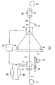
- FIG. 1 shows a reserve 1 of smooth dielectric support 2 transformed into grooved support at the machining station 3 associated with the chip elimination station 4.
- the grooved support receives the optical fibers provided by reserves 6 arranged on a plate 7 secured to a laying head 8.
- the grooved support provided with optical fibers 9 is surrounded by a protective tape 10 provided by a taping machine 11.
- a drawing device is shown at 12 and at 13 a reception serving as a reserve for the cable element.
- a starting 1 a drawing 12 and a rotating reception 13
- the other elements of the line being fixed.
- a machining station 3-4 and a laying station, of rotating fibers 8-7 are produced, the other elements of the line remaining fixed.
- 14 shows a servo device used in this second variant to ensure the synchronization of the laying station 8 from the machining station 3.
- the machining of alternating pitch grooves is done in a similar manner.
- the machining station 3-4 is mounted on a table 15 movable in translation, in the direction 16 of travel of the cable, under the action of a motor 17.
- the machining being done when hot, a source has been shown at 18 bringing the machining station 3 to the optimum temperature, taking into account in particular the speed of travel, of the support material 2.
- the machining station 3 comprises a temperature sensor delivering a signal used in 19 for source regulation 18. In this way, the line can be fully automated.
- Stations 1, 11, 12 and 13 are standard elements commercially available.
- the fiber laying assembly 6-7-8 is of the type described in French patent application No. 2,418,940 already cited, and the chip removal device 4 is of the type described in the certificate request addition n ° 2.428.513 already cited.
- the machining station 3 is shown in detail in the following figures.
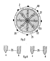
- the machining head 3 seen from the front in FIG. 2, consists of a set of teeth 20 arranged regularly along the radii of a circumference, the center of which is occupied by the support 2 in housings of an annular mount. 27, the downstream face of which has been eliminated in FIG. 2 (cf. axis 2-2, fig. 5a).
- Each tooth 20 carries an axial lug 22 penetrating into a slot 23 curved relative to the axis of the tooth, and formed in a crown 21.
- a control ring 40 has the effect of locking the lug 22 at one or the other end of the slot 23, according to its own position as will be explained later.
- a locking device visible in FIGS. 5 and 6 cooperating with each tooth is carried by the crown 21, movable in rotation relative to the frame 27, as will be explained in more detail with reference to FIGS. 5.
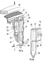
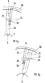
- FIG. 3A represents a perspective view of a tooth mounted in the machining head and FIG. 38 a view of the isolated tooth after turning 180 ° around a vertical axis.
- the tooth comprises a solid body 26 terminated by a thinned cutting point 25, the end of which enters the support 2 moving in the direction of the arrow 16.
- the solid body 26 supports the lug 22 penetrating into the inclined slot 23.
- the body of the tooth has two bores respectively 28 and 29 (fig.3 B ), one of which extends into the point 25. These bores serve respectively as housing for a heating resistor 30 and a temperature sensor 31 making it possible to bring the tooth to the desired temperature and to maintain it at this temperature, as is well known.
- the tooth is engaged in a housing 32 constituted by a notch in the annular frame 27 whose bottom 33 has been cut to allow a clearer representation of the tooth.
- the representation of the front view of FIG. 2 is made in a plane perpendicular to the axis of the part 2 to be machined located downstream of the bottom 33 (in the direction of travel) thus 1 u'il is represented by axis 2-2 of figure 5.
- the housing 32 reproduces the shape of the tooth, the lower face 34 (FIG. 3B ) of the solid body 26 is located opposite a shoulder 35 of the frame 27 playing the role of stop as it appears in FIG. 5B .
- the housing 32 is extended radially by a narrowed portion used for guiding the tip 25 which is held between the internal face 33 and the face extending the shoulder 35.
- the crown 21, coaxial with the frame 27, surrounds the visible part of 27. As it appears in FIGS. 5, the crown 21 occupies a groove machined in the frame 27. It is movable in rotation relative to the frame 27 and carries the locking device of the teeth 20 (shown at 37-39 in FIGS. 5), not shown in FIG. 3. The locking is ensured by a trigger 37 which immobilizes the lug 22 in the slot 23.
- the ring of control 40 acts on the locking device and on the angular position of the crown 21.
- the lug 22 is attached to the solid body 26 at the bottom of a groove 41.
- the position of the lug 22 in the groove is adjusted during the manufacture of the tooth and is final.
- the position of the lug makes it possible to adjust the penetration depth of the point 25 of each tooth in the support 2 to be machined. Adjustment of the lug fixing is carried out before starting the line using a model machined to the desired profile replacing the support 2.
- FIG. 4 schematically represents sectional views of variants of the tips of the teeth.
- FIG. 4a represents the variant appearing in FIG. 3 in which the point 25 is triangular.
- FIG. 4b represents a tooth with a rectangular profile making it possible to dig larger grooves than the previous variant. It is used for large diameter fibers.
- FIG. 4c represents a tooth whose end is truncated.
- Figure 4d corresponding to the preferred variant when the support is made of medium density polyethylene, has a point in the shape of a truncated curvilinear triangle. This profile eliminates the risk of blockage of the fiber at the bottom of the groove and facilitates machining by reducing the cutting force.
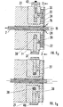
- 5A and 5B show, in sectional view, along a diameter, the machining head respectively in the working position and rest.
- FIGS. 6A and 6 8 are diagrams of certain elements of the head, seen in elevation, respectively under the same conditions.
- the traces of the section plane of FIG. 5 are represented by the axis 5-5, in FIGS. 6.
- FIG. 6A This locking device comprises a trigger 37 which can move radially in a groove hollowed out in the crown 21, as shown by the arrow, under the action of a centrifugal force exerted by a spring 38 occupying the bottom of the groove and of the pressure exerted by the control ring 40.
- the trigger 37 carries a finger 39 which, penetrating into the slot 23, presses on the lug 22 and blocks the lug at the lower end of the slot. Under the action of the ring 40 causing the stop (fig. 5 B ) the trigger 37 is pressed in its housing, crushing the spring 38 and the ring 40 immobilizes the crown 21.
- the frame 27 continues its rotation and the lug 22 follows the slot 23. The inclination of this makes the tooth 20 go up radially and separates its point 25 from the groove of the support 2. Once the teeth are apart, the machining assembly 3-4 is moved towards the upstream by the motor 17 (fig. 1).
- the mount 27 Upon start-up, the mount 27 is rotated in the opposite direction to the rotation at the time of stopping.
- the lug 22, along the slot 23, causes the tooth to move radially towards the axis to its working position.
- the movement of the control ring 40 releases the trigger 37 which, under the action of the spring 38, returns to its working position.
- the finger 39 blocks the lug 22 in the slot 23.
- the machining head is in working condition.
- the motor 17 returns the head to its working position and the rotation of the mount 27 is reversed. Self-centering occurs. Support training then resumes.
Landscapes
- Engineering & Computer Science (AREA)
- Physics & Mathematics (AREA)
- Life Sciences & Earth Sciences (AREA)
- Forests & Forestry (AREA)
- Mechanical Engineering (AREA)
- Manufacturing & Machinery (AREA)
- General Physics & Mathematics (AREA)
- Optics & Photonics (AREA)
- Milling Processes (AREA)
- Light Guides In General And Applications Therefor (AREA)
- Mechanical Coupling Of Light Guides (AREA)
Applications Claiming Priority (2)
| Application Number | Priority Date | Filing Date | Title |
|---|---|---|---|
| FR7912282A FR2456959A1 (fr) | 1979-05-15 | 1979-05-15 | Poste d'usinage pour ligne de fabrication d'elements de cables a fibres optiques et ligne de fabrication l'incorporant |
| FR7912282 | 1979-05-15 |
Publications (2)
| Publication Number | Publication Date |
|---|---|
| EP0019500A1 EP0019500A1 (fr) | 1980-11-26 |
| EP0019500B1 true EP0019500B1 (fr) | 1983-02-16 |
Family
ID=9225469
Family Applications (1)
| Application Number | Title | Priority Date | Filing Date |
|---|---|---|---|
| EP19800400503 Expired EP0019500B1 (fr) | 1979-05-15 | 1980-04-15 | Poste d'usinage en continu de rainures dans un support de câble à fibres optiques et utilisation d'un tel poste |
Country Status (6)
| Country | Link |
|---|---|
| US (1) | US4382732A (ref) |
| EP (1) | EP0019500B1 (ref) |
| JP (1) | JPS55153905A (ref) |
| CA (1) | CA1156027A (ref) |
| DE (1) | DE3061982D1 (ref) |
| FR (1) | FR2456959A1 (ref) |
Families Citing this family (4)
| Publication number | Priority date | Publication date | Assignee | Title |
|---|---|---|---|---|
| IT1138823B (it) * | 1981-06-26 | 1986-09-17 | Pirelli Cavi Spa | Metodo ed apparecchiatura per la produzione di scanalature in un filamento allungato |
| JPS59192205A (ja) * | 1983-04-15 | 1984-10-31 | Furukawa Electric Co Ltd:The | 光フアイバケ−ブルの製造方法 |
| JPS63269110A (ja) * | 1987-04-27 | 1988-11-07 | Nippon Telegr & Teleph Corp <Ntt> | 伝送媒体用スペ−サ−の製造方法 |
| JPH067211B2 (ja) * | 1988-10-19 | 1994-01-26 | 東鳩製菓株式会社 | 伝送媒体用金属スペーサーの製造方法 |
Family Cites Families (9)
| Publication number | Priority date | Publication date | Assignee | Title |
|---|---|---|---|---|
| US2569566A (en) * | 1948-07-26 | 1951-10-02 | Harold L Hoffman | Machine tool |
| US2865238A (en) * | 1954-10-22 | 1958-12-23 | Groov Pin Corp | Equipment for forming chiseled grooves in rods or the like |
| NL301013A (ref) * | 1962-11-27 | |||
| GB1107253A (en) * | 1963-12-10 | 1968-03-27 | Submarine Cables Ltd | Method and apparatus for producing plastic insulated electrical conductors |
| FR1476393A (fr) * | 1966-04-19 | 1967-04-07 | Little Inc A | Appareil et procédé pour former un filet hélicoïdal dans la surface d'un cylindre allongé en matière thermoplastique |
| US3491651A (en) * | 1967-10-03 | 1970-01-27 | Ford Motor Co | Heated loop type cutter and controlled temperature spindle |
| FR2052016A5 (en) * | 1969-07-04 | 1971-04-09 | Cables De Lyon Geoffroy Delore | Waste guide for a rotating cutter |
| DE2651725C2 (de) * | 1976-11-11 | 1978-12-14 | Aeg-Telefunken Kabelwerke Ag, Rheydt, 4050 Moenchengladbach | Verfahren zur Herstellung eines optischen Kabels |
| DE2861661D1 (en) * | 1978-01-04 | 1982-04-08 | Lignes Telegraph Telephon | Apparatus for continuously machining helicoidal grooves in a cylindrical object |
-
1979
- 1979-05-15 FR FR7912282A patent/FR2456959A1/fr active Granted
-
1980
- 1980-04-15 EP EP19800400503 patent/EP0019500B1/fr not_active Expired
- 1980-04-15 DE DE8080400503T patent/DE3061982D1/de not_active Expired
- 1980-05-12 CA CA000351791A patent/CA1156027A/en not_active Expired
- 1980-05-12 US US06/148,992 patent/US4382732A/en not_active Expired - Lifetime
- 1980-05-13 JP JP6329980A patent/JPS55153905A/ja active Pending
Also Published As
| Publication number | Publication date |
|---|---|
| FR2456959A1 (fr) | 1980-12-12 |
| FR2456959B1 (ref) | 1982-10-01 |
| EP0019500A1 (fr) | 1980-11-26 |
| JPS55153905A (en) | 1980-12-01 |
| US4382732A (en) | 1983-05-10 |
| DE3061982D1 (en) | 1983-03-24 |
| CA1156027A (en) | 1983-11-01 |
Similar Documents
| Publication | Publication Date | Title |
|---|---|---|
| EP0011561A1 (fr) | Procédé de mise en place d'une fibre optique dans un embout de connecteur | |
| EP0051510B1 (fr) | Dispositif de positionnement de fibres optiques dans une pièce formant embout destinée au raccordement de deux câbles de transmission par fibres optiques | |
| FR2634073A1 (fr) | Appareil a denuder des fils et sertir des bornes et dispositif de coupe d'isolant et de denudage | |
| FR2494453A1 (fr) | Procede de reconstitution de la gaine exterieure en plastique sur une epissure de fibres optiques | |
| EP0524121A1 (fr) | Dispositif de dénudage de la surface d'un conducteur récouvert d'une isolant de protectrice | |
| EP0255425B1 (fr) | Dispositif pour la mise en forme automatique d'une nappe de fibres sur un moule, ainsi que machines comportant un tel dispositif | |
| EP0058594B1 (fr) | Tête de pose simultanée de fibres optiques dans un support cylindrique rainuré et dispositif de fabrication d'éléments de câblage comportant une telle tête | |
| EP0216695B1 (fr) | Procédé et machine pour la fabrication de pièces creuses de revolution formées de fils s'étendant selon trois directions différentes | |
| EP0019500B1 (fr) | Poste d'usinage en continu de rainures dans un support de câble à fibres optiques et utilisation d'un tel poste | |
| EP0011539B1 (fr) | Procédé et dispositif pour la fabrication d'un profilé cylindrique alvéolé | |
| FR2576245A1 (fr) | Procede d'enrobage d'un capteur allonge, dispositif de moulage pour la mise en oeuvre du procede, capteur obtenu et armature intervenant dans la fabrication du capteur | |
| CA1103908A (fr) | Fabrication d'elements de cablage comportant des fibres optiques | |
| EP0375530A1 (fr) | Outil pour dénuder des câbles, notamment des câbles constitués | |
| EP0002976B1 (fr) | Dispositif d'usinage en continu de rainures en hélice sur une tige cylindrique | |
| EP0056541B1 (fr) | Dispositif de support d'un outil d'usinage d'une tige cylindrique et tête d'usinage comportant un tel dispositif | |
| EP0768548B1 (fr) | Dispositif permettant de faciliter la réalisation de connectiques de fibres optiques | |
| FR2577751A1 (fr) | Machine a elaguer et ebourgeonner les sarments de vigne | |
| EP0444566B1 (fr) | Pince de coupe, à faible encombrement, pour fibre optique | |
| FR2493618A1 (fr) | Procede et dispositif de denudage d'un cable | |
| FR2604939A1 (fr) | Procede de coupe d'un tube pour coupeuse de tubes, et dispositif pour la mise en oeuvre de ce procede | |
| FR2614142A1 (fr) | Dispositif de denudage d'un fil gaine | |
| EP0096608A1 (fr) | Collimateur pour fibre optique, application à la réalisation de dispositifs de commutation optique | |
| FR2540026A1 (fr) | Dispositif de faconnage de produits en materiau leger | |
| FR2684499A1 (fr) | Procede de preparation de coupe et de pre-denudage pour cable ou fil conducteur et appareil pour sa mise en óoeuvre. | |
| EP0263763B1 (fr) | Machine pour la préparation automatique des extrémités à raccorder des tuyaux souples en caoutchouc armé |
Legal Events
| Date | Code | Title | Description |
|---|---|---|---|
| PUAI | Public reference made under article 153(3) epc to a published international application that has entered the european phase |
Free format text: ORIGINAL CODE: 0009012 |
|
| AK | Designated contracting states |
Designated state(s): BE CH DE GB IT NL |
|
| 17P | Request for examination filed |
Effective date: 19810105 |
|
| ITF | It: translation for a ep patent filed | ||
| GRAA | (expected) grant |
Free format text: ORIGINAL CODE: 0009210 |
|
| AK | Designated contracting states |
Designated state(s): BE CH DE GB IT LI NL |
|
| REF | Corresponds to: |
Ref document number: 3061982 Country of ref document: DE Date of ref document: 19830324 |
|
| PGFP | Annual fee paid to national office [announced via postgrant information from national office to epo] |
Ref country code: CH Payment date: 19840322 Year of fee payment: 5 |
|
| PGFP | Annual fee paid to national office [announced via postgrant information from national office to epo] |
Ref country code: BE Payment date: 19840331 Year of fee payment: 5 |
|
| PGFP | Annual fee paid to national office [announced via postgrant information from national office to epo] |
Ref country code: DE Payment date: 19840402 Year of fee payment: 5 |
|
| PGFP | Annual fee paid to national office [announced via postgrant information from national office to epo] |
Ref country code: NL Payment date: 19860430 Year of fee payment: 7 |
|
| PG25 | Lapsed in a contracting state [announced via postgrant information from national office to epo] |
Ref country code: LI Effective date: 19870430 Ref country code: CH Effective date: 19870430 |
|
| BERE | Be: lapsed |
Owner name: LIGNES TELEGRAPHIQUES ET TELEPHONIQUES L.T.T. Effective date: 19870430 |
|
| PG25 | Lapsed in a contracting state [announced via postgrant information from national office to epo] |
Ref country code: NL Effective date: 19871101 |
|
| NLV4 | Nl: lapsed or anulled due to non-payment of the annual fee | ||
| GBPC | Gb: european patent ceased through non-payment of renewal fee | ||
| REG | Reference to a national code |
Ref country code: CH Ref legal event code: PL |
|
| PG25 | Lapsed in a contracting state [announced via postgrant information from national office to epo] |
Ref country code: DE Effective date: 19880101 |
|
| PG25 | Lapsed in a contracting state [announced via postgrant information from national office to epo] |
Ref country code: GB Effective date: 19881118 |
|
| PG25 | Lapsed in a contracting state [announced via postgrant information from national office to epo] |
Ref country code: BE Effective date: 19890430 |
|
| PLBE | No opposition filed within time limit |
Free format text: ORIGINAL CODE: 0009261 |
|
| STAA | Information on the status of an ep patent application or granted ep patent |
Free format text: STATUS: NO OPPOSITION FILED WITHIN TIME LIMIT |