EP0019500B1 - Post for on line manufacturing of grooves in a beam of optical fibres and use of such a post - Google Patents
Post for on line manufacturing of grooves in a beam of optical fibres and use of such a post Download PDFInfo
- Publication number
- EP0019500B1 EP0019500B1 EP19800400503 EP80400503A EP0019500B1 EP 0019500 B1 EP0019500 B1 EP 0019500B1 EP 19800400503 EP19800400503 EP 19800400503 EP 80400503 A EP80400503 A EP 80400503A EP 0019500 B1 EP0019500 B1 EP 0019500B1
- Authority
- EP
- European Patent Office
- Prior art keywords
- grooves
- tooth
- unit
- carrier
- optical fibres
- Prior art date
- Legal status (The legal status is an assumption and is not a legal conclusion. Google has not performed a legal analysis and makes no representation as to the accuracy of the status listed.)
- Expired
Links
- 238000004519 manufacturing process Methods 0.000 title claims description 17
- 230000003287 optical effect Effects 0.000 title claims 8
- 239000000835 fiber Substances 0.000 claims description 13
- 238000005520 cutting process Methods 0.000 claims description 9
- 239000007787 solid Substances 0.000 claims description 6
- 238000010438 heat treatment Methods 0.000 claims description 5
- 230000000284 resting effect Effects 0.000 claims 2
- 238000003754 machining Methods 0.000 description 41
- 239000013307 optical fiber Substances 0.000 description 8
- 238000006073 displacement reaction Methods 0.000 description 7
- 238000000034 method Methods 0.000 description 5
- 238000013021 overheating Methods 0.000 description 3
- 230000000149 penetrating effect Effects 0.000 description 3
- 230000006378 damage Effects 0.000 description 2
- 239000000463 material Substances 0.000 description 2
- 229920001179 medium density polyethylene Polymers 0.000 description 2
- 239000004701 medium-density polyethylene Substances 0.000 description 2
- 239000012815 thermoplastic material Substances 0.000 description 2
- 238000011144 upstream manufacturing Methods 0.000 description 2
- 208000027418 Wounds and injury Diseases 0.000 description 1
- 238000010924 continuous production Methods 0.000 description 1
- 238000010586 diagram Methods 0.000 description 1
- 230000000694 effects Effects 0.000 description 1
- 230000008030 elimination Effects 0.000 description 1
- 238000003379 elimination reaction Methods 0.000 description 1
- 230000004927 fusion Effects 0.000 description 1
- 208000014674 injury Diseases 0.000 description 1
- 238000003801 milling Methods 0.000 description 1
- 230000035515 penetration Effects 0.000 description 1
- 239000004033 plastic Substances 0.000 description 1
- 229920003023 plastic Polymers 0.000 description 1
- 230000001681 protective effect Effects 0.000 description 1
Images
Classifications
-
- G—PHYSICS
- G02—OPTICS
- G02B—OPTICAL ELEMENTS, SYSTEMS OR APPARATUS
- G02B6/00—Light guides; Structural details of arrangements comprising light guides and other optical elements, e.g. couplings
- G02B6/44—Mechanical structures for providing tensile strength and external protection for fibres, e.g. optical transmission cables
- G02B6/4479—Manufacturing methods of optical cables
- G02B6/4489—Manufacturing methods of optical cables of central supporting members of lobe structure
-
- B—PERFORMING OPERATIONS; TRANSPORTING
- B26—HAND CUTTING TOOLS; CUTTING; SEVERING
- B26D—CUTTING; DETAILS COMMON TO MACHINES FOR PERFORATING, PUNCHING, CUTTING-OUT, STAMPING-OUT OR SEVERING
- B26D1/00—Cutting through work characterised by the nature or movement of the cutting member or particular materials not otherwise provided for; Apparatus or machines therefor; Cutting members therefor
-
- B—PERFORMING OPERATIONS; TRANSPORTING
- B26—HAND CUTTING TOOLS; CUTTING; SEVERING
- B26D—CUTTING; DETAILS COMMON TO MACHINES FOR PERFORATING, PUNCHING, CUTTING-OUT, STAMPING-OUT OR SEVERING
- B26D3/00—Cutting work characterised by the nature of the cut made; Apparatus therefor
- B26D3/06—Grooving involving removal of material from the surface of the work
-
- Y—GENERAL TAGGING OF NEW TECHNOLOGICAL DEVELOPMENTS; GENERAL TAGGING OF CROSS-SECTIONAL TECHNOLOGIES SPANNING OVER SEVERAL SECTIONS OF THE IPC; TECHNICAL SUBJECTS COVERED BY FORMER USPC CROSS-REFERENCE ART COLLECTIONS [XRACs] AND DIGESTS
- Y10—TECHNICAL SUBJECTS COVERED BY FORMER USPC
- Y10S—TECHNICAL SUBJECTS COVERED BY FORMER USPC CROSS-REFERENCE ART COLLECTIONS [XRACs] AND DIGESTS
- Y10S82/00—Turning
- Y10S82/90—Lathe thermal regulation
-
- Y—GENERAL TAGGING OF NEW TECHNOLOGICAL DEVELOPMENTS; GENERAL TAGGING OF CROSS-SECTIONAL TECHNOLOGIES SPANNING OVER SEVERAL SECTIONS OF THE IPC; TECHNICAL SUBJECTS COVERED BY FORMER USPC CROSS-REFERENCE ART COLLECTIONS [XRACs] AND DIGESTS
- Y10—TECHNICAL SUBJECTS COVERED BY FORMER USPC
- Y10T—TECHNICAL SUBJECTS COVERED BY FORMER US CLASSIFICATION
- Y10T408/00—Cutting by use of rotating axially moving tool
- Y10T408/83—Tool-support with means to move Tool relative to tool-support
- Y10T408/85—Tool-support with means to move Tool relative to tool-support to move radially
- Y10T408/852—Tool-support with means to move Tool relative to tool-support to move radially with Tool releasing trigger
-
- Y—GENERAL TAGGING OF NEW TECHNOLOGICAL DEVELOPMENTS; GENERAL TAGGING OF CROSS-SECTIONAL TECHNOLOGIES SPANNING OVER SEVERAL SECTIONS OF THE IPC; TECHNICAL SUBJECTS COVERED BY FORMER USPC CROSS-REFERENCE ART COLLECTIONS [XRACs] AND DIGESTS
- Y10—TECHNICAL SUBJECTS COVERED BY FORMER USPC
- Y10T—TECHNICAL SUBJECTS COVERED BY FORMER US CLASSIFICATION
- Y10T409/00—Gear cutting, milling, or planing
- Y10T409/50—Planing
- Y10T409/502624—Means for cutting groove
-
- Y—GENERAL TAGGING OF NEW TECHNOLOGICAL DEVELOPMENTS; GENERAL TAGGING OF CROSS-SECTIONAL TECHNOLOGIES SPANNING OVER SEVERAL SECTIONS OF THE IPC; TECHNICAL SUBJECTS COVERED BY FORMER USPC CROSS-REFERENCE ART COLLECTIONS [XRACs] AND DIGESTS
- Y10—TECHNICAL SUBJECTS COVERED BY FORMER USPC
- Y10T—TECHNICAL SUBJECTS COVERED BY FORMER US CLASSIFICATION
- Y10T409/00—Gear cutting, milling, or planing
- Y10T409/50—Planing
- Y10T409/509348—Tool head
- Y10T409/509676—Tool head with means to permit repositioning of cutting for idle return stroke
- Y10T409/50984—Tool head with means to permit repositioning of cutting for idle return stroke comprising pivotable cutter or cutter support
-
- Y—GENERAL TAGGING OF NEW TECHNOLOGICAL DEVELOPMENTS; GENERAL TAGGING OF CROSS-SECTIONAL TECHNOLOGIES SPANNING OVER SEVERAL SECTIONS OF THE IPC; TECHNICAL SUBJECTS COVERED BY FORMER USPC CROSS-REFERENCE ART COLLECTIONS [XRACs] AND DIGESTS
- Y10—TECHNICAL SUBJECTS COVERED BY FORMER USPC
- Y10T—TECHNICAL SUBJECTS COVERED BY FORMER US CLASSIFICATION
- Y10T82/00—Turning
- Y10T82/16—Severing or cut-off
- Y10T82/16229—Interrelated means for tool infeed and circumrotation
- Y10T82/16262—Infeed cam disk rotation geared to tool holder rotation
- Y10T82/16311—Scroll plate infeed cam
-
- Y—GENERAL TAGGING OF NEW TECHNOLOGICAL DEVELOPMENTS; GENERAL TAGGING OF CROSS-SECTIONAL TECHNOLOGIES SPANNING OVER SEVERAL SECTIONS OF THE IPC; TECHNICAL SUBJECTS COVERED BY FORMER USPC CROSS-REFERENCE ART COLLECTIONS [XRACs] AND DIGESTS
- Y10—TECHNICAL SUBJECTS COVERED BY FORMER USPC
- Y10T—TECHNICAL SUBJECTS COVERED BY FORMER US CLASSIFICATION
- Y10T82/00—Turning
- Y10T82/25—Lathe
- Y10T82/2527—Lathe having hollow cutter head
-
- Y—GENERAL TAGGING OF NEW TECHNOLOGICAL DEVELOPMENTS; GENERAL TAGGING OF CROSS-SECTIONAL TECHNOLOGIES SPANNING OVER SEVERAL SECTIONS OF THE IPC; TECHNICAL SUBJECTS COVERED BY FORMER USPC CROSS-REFERENCE ART COLLECTIONS [XRACs] AND DIGESTS
- Y10—TECHNICAL SUBJECTS COVERED BY FORMER USPC
- Y10T—TECHNICAL SUBJECTS COVERED BY FORMER US CLASSIFICATION
- Y10T83/00—Cutting
- Y10T83/283—With means to control or modify temperature of apparatus or work
- Y10T83/293—Of tool
Description
La présente invention concerne les machines de fabrication de câbles élémentaires constitués par un support rigide diélectrique présentant des gorges ou rainures dans lesquelles sont placées des fibres optiques protégées par un rubanage ultérieur. Un élément de câble à fibres optiques de ce type est décrit dans la demande de brevet français publiée le 15 septembre 1978 sous le n° 2.381.326, pour: « Elément de câble incorporant des fibres optiques ».The present invention relates to machines for manufacturing elementary cables constituted by a rigid dielectric support having grooves or grooves in which are placed optical fibers protected by subsequent tape. A fiber optic cable element of this type is described in the French patent application published on September 15, 1978 under No. 2,381,326, for: "Cable element incorporating optical fibers".
La demande de brevet français publiée le 3 août 1979 sous le n° 2.413.962, pour: « Procédé d'usinage en continu de support pour guides d'ondes électromagnétiques et sa première addition publiée le 11 janvier 1980 sous le n° 2.428.513, décrivent un procédé d'usinage en continu de rainures, hélicoîdales ou à pas alterné, dans un jonc diélectrique en vue de réaliser notamment le support des fibres optiques d'un élément de câble à fibres optiques. La demande de brevet français publiée le 28 septembre 1979 sous le n° 2.418.940, pour : « Perfectionnements à la fabrication d'éléments de câblage comportant des fibres optiques décrit un dispositif susceptible d'assurer la pose simultanée en continu de l'ensemble des fibres optiques dans les rainures d'un support cylindrique préalablement usiné. La mise en tandem de ces deux postes (usinage et pose) dans une ligne de production en continu d'éléments de câble présente des difficultés en cours d'exploitation résultant notamment des interruptions inévitables et se présentant plus particulièrement à la mise en route de la ligne de production. En effet, ainsi qu'il est expliqué dans la demande de brevet français publiée le 3 août 1979 sous le n° 2.413.962, pour: « Procédé d'usinage en continu de support pour guides d'ondes électromagnétiques », l'usinage des rainures se fait à chaud, à une température dépendant de la nature du matériau constituant le support, température qui est de l'ordre de 200 °C dans le cas du polyéthylène à moyenne densité. Un arrêt, accidentel ou non, du poste d'usinage entraîne l'immobilisation du support et une surchauffe locale de la zone qui se trouve au voisinage de l'outil, par suite de l'inertie thermique de celui-ci. La reprise de l'usinage ne peut donc être effectuée par simple remise en route du poste d'usinage, une certaine longueur de support ayant été endommagée par la surchauffe subie. Il n'est donc pas possible d'incorporer le poste d'usinage tel que décrit dans la demande ci- dessus dans une ligne de fabrication qui doit nécessairement pouvoir être arrêtée et remise en route sans dommage pour les éléments constituant le câble.The French patent application published on August 3, 1979 under No. 2,413,962, for: “Process of continuous machining of support for electromagnetic waveguides and its first addition published on January 11, 1980 under No. 2,428. 513, describe a process for the continuous machining of grooves, helical or with alternating pitch, in a dielectric rod with a view in particular to supporting the optical fibers of an optical fiber cable element. The French patent application published on September 28, 1979 under No. 2,418,940, for: "Improvements in the manufacture of wiring elements comprising optical fibers describes a device capable of ensuring the simultaneous continuous laying of the assembly optical fibers in the grooves of a cylindrical support previously machined. The setting up in tandem of these two stations (machining and laying) in a continuous production line for cable elements presents difficulties during operation resulting in particular from unavoidable interruptions and which arise more particularly when the production line. Indeed, as explained in the French patent application published on August 3, 1979 under No. 2,413,962, for: "Process of continuous machining of support for electromagnetic waveguides", machining grooves is made hot, at a temperature depending on the nature of the material constituting the support, a temperature which is of the order of 200 ° C. in the case of medium density polyethylene. A stop, accidental or not, of the machining station results in the immobilization of the support and local overheating of the zone which is in the vicinity of the tool, as a result of the thermal inertia of the latter. Resumption of machining cannot therefore be carried out by simply restarting the machining station, a certain length of support having been damaged by the overheating suffered. It is therefore not possible to incorporate the machining station as described in the above request into a manufacturing line which must necessarily be able to be stopped and restarted without damage to the elements constituting the cable.
On connaît également d'autres techniques permettant d'usiner des rainures, par exemple héli- coïdales, dans un support cylindrique. On se reportera par exemple au brevet français n° 1.476.393 délivré le 27 février 1967, pour: « Appareil et procédé pour former un filet hélicoïdal dans la surface d'un cylindre allongé en matière thermoplastique ». Selon ce brevet, chaque rainure est formée à l'aide d'un soc chauffa- ble dont la pointe pénètre par fusion dans la matière thermoplastique à l'état ramolli. On citera également le brevet français n° 1.350.724 délivré le 23 décembre 1963, pour : « Perfectionnements aux quartes et procédé de fabrication », selon lequel les rainures sont formées par fraisage au moyen d'un ensemble de fraises disposées de façon à permettre la fabrication en continu et en une seule opération de la quarte.Other techniques are also known for machining grooves, for example helical grooves, in a cylindrical support. Reference is made, for example, to French patent No. 1,476,393 issued on February 27, 1967, for: "Apparatus and method for forming a helical thread in the surface of an elongated cylinder made of thermoplastic material". According to this patent, each groove is formed using a heated share, the point of which penetrates by fusion into the thermoplastic material in the softened state. Mention will also be made of French patent n ° 1,350,724 issued on December 23, 1963, for: "Improvements in quartes and manufacturing process", according to which the grooves are formed by milling by means of a set of cutters arranged so as to allow continuous manufacturing in a single operation of the fourth.
La présente invention a pour objet un poste d'usinage en continu de rainures dans un support cylindrique en matière plastique susceptible d'être introduit dans une ligne de fabrication d'éléments de câble à fibres optiques, c'est-à-dire permettant d'effectuer, en ligne, les opérations d'usinage des rainures dans le support, de pose des fibres dans les rainures et de pose des protection et enveloppe.The subject of the present invention is a station for continuously machining grooves in a cylindrical plastic support capable of being introduced into a line for manufacturing fiber optic cable elements, that is to say allowing '' carry out, on line, the machining operations of the grooves in the support, of laying the fibers in the grooves and of fitting the protection and casing.
Selon l'une des caractéristiques essentielles de l'invention, le poste d'usinage de rainures comporte un ensemble de dents radiales en nombre égal à celui des rainures à former, associé à une monture annulaire et à une couronne coaxiale mobile par rapport à la monture, la rotation relative de la couronne par rapport à la monture assurant un déplacement radial des dents et permettant un positionnement indépendant de chacune des dents ; le poste comporte également des moyens permettant un déplacement en translation de la monture parallèlement au défilement du support de fibre.According to one of the essential characteristics of the invention, the groove machining station comprises a set of radial teeth in a number equal to that of the grooves to be formed, associated with an annular mount and with a coaxial ring movable relative to the frame, the relative rotation of the crown relative to the frame ensuring a radial displacement of the teeth and allowing independent positioning of each of the teeth; the post also includes means allowing a displacement in translation of the frame parallel to the movement of the fiber support.
En position de marche normale, le poste d'usinage est disposé le plus près possible de la tête de pose des fibres. De préférence, un dispositif d'aspiration des copeaux est disposé en amont du poste d'usinage et associé à celui-ci. La tête de pose des fibres est, de préférence, du type décrit dans la demande de brevet français n° 2.418.940 déjà citée, et elle est asservie au poste d'usinage des rainures.In the normal operating position, the machining station is placed as close as possible to the fiber laying head. Preferably, a chip suction device is arranged upstream of the machining station and associated with it. The fiber laying head is preferably of the type described in French patent application No. 2,418,940 already cited, and it is controlled by the machining station of the grooves.
Selon un aspect de l'invention, chacune des dents comprend son propre élément de chauffage, placé au voisinage de la zone coupante, et un capteur thermosensible qui alimente un circuit de commande de la température de ladite dent.According to one aspect of the invention, each of the teeth comprises its own heating element, placed in the vicinity of the cutting zone, and a thermosensitive sensor which supplies a circuit for controlling the temperature of said tooth.
Selon un mode de réalisation particulier de l'invention, le profil de la pointe coupante des dents est un triangle curviligne.According to a particular embodiment of the invention, the profile of the cutting tip of the teeth is a curvilinear triangle.
Selon une forme d'exécution de l'invention, la couronne occupe une gorge pratiquée dans la monture annulaire, et porte des dispositifs de blocage des dents placés dans des logements individuels de ladite couronne.According to one embodiment of the invention, the crown occupies a groove formed in the annular frame, and carries teeth locking devices placed in individual housings of said crown.
Le poste selon l'invention a pour avantage une grande souplesse de fonctionnement. En cas d'arrêt du poste, les dents sont escamotées radialement ; l'usinage des rainures est arrêté sans blessure du support diélectrique. Le retrait des dents supprime toute surchauffe. L'asservissement en température de chacune des dents permet un réglage précis des conditions de coupe et améliore l'état de surface des rainures. Le déplacement longitudinal de la tête d'usinage permet de reprendre l'usinage de l'élément en conservant les caractéristiques géométriques et l'état de surface des rainures. Avant la remise en route de la ligne de fabrication, la tête d'usinage ayant été déplacée en aval de la position de fonctionnement, les dents se positionnent progressivement spontanément dans les rainures à mesure que l'ensemble d'usinage reprend sa position de fonctionnement. La remise en route de la ligne assure la continuité des rainures.The station according to the invention has the advantage of great operating flexibility. In the event of station shutdown, the teeth are retracted radially; the machining of the grooves is stopped without injury to the dielectric support. The withdrawal of teeth removes any overheating. The temperature control of each of the teeth allows precise adjustment of the cutting conditions and improves the surface condition of the grooves. The longitudinal displacement of the machining head makes it possible to resume machining of the element while preserving the geometrical characteristics and the surface condition of the grooves. Before restarting the production line, the machining head having been moved downstream from the operating position, the teeth are progressively positioned spontaneously in the grooves as the machining assembly returns to its operating position . The restarting of the line ensures the continuity of the grooves.
Le déplacement radial des dents permet de contrôler la profondeur de coupe et facilite le réglage de la coupe pour un profil de dent donné. L'utilisation des dents démontables facilite leur réalisation par des moyens classiques d'usinage et permet d'obtenir une meilleure définition géométrique de la partie coupante et des tolérances plus faibles.The radial displacement of the teeth makes it possible to control the depth of cut and facilitates the adjustment of the cut for a given tooth profile. The use of removable teeth facilitates their realization by conventional means of machining and makes it possible to obtain a better geometric definition of the cutting part and lower tolerances.
L'invention sera bien comprise en se reportant à la description suivante et aux figures qui l'accompagnent dans lesquelles :
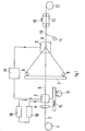
- la figure 1 est une vue générale d'une ligne de fabrication comprenant un poste d'usinage selon l'invention ;
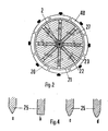
- la figure 2 est une vue de face d'une réalisation de l'outil d'usinage ;
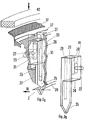
- les figures 3 sont une vue en perspective d'une dent de coupe montée et d'une dent séparée de l'outil ;
- les figures 4 représentent en section des variantes des pointes de dents ;
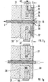
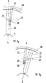
- les figures 5 sont des vues en coupe de la tête d'usinage en position de travail et de repos ;
- les figures 6 expliquent le déplacement radial des dents.
- Figure 1 is a general view of a manufacturing line comprising a machining station according to the invention;
- Figure 2 is a front view of an embodiment of the machining tool;
- Figures 3 are a perspective view of a mounted cutting tooth and a tooth separated from the tool;
- Figures 4 show in section variants of the tooth tips;
- Figures 5 are sectional views of the machining head in the working and rest position;
- Figures 6 explain the radial displacement of the teeth.
On a représenté sur la figure 1 une réserve 1 de support diélectrique lisse 2 transformé en support rainuré au poste d'usinage 3 associé au poste d'éliminatin des copeaux4. Le support rainuré reçoit les fibres optiques fournies par des réserves 6 disposées sur un plateau 7 solidaire d'une tête de pose 8.FIG. 1 shows a
Le support rainuré muni de fibres optiques 9 est entouré d'un ruban 10 de protection fourni par une rubaneuse 11. On a représenté en 12 un dispositif de tirage et en 13 une réception servant de réserve de l'élément de câble. Suivant les besoins, dans le cas de rainures hélicoïdales, on peut disposer d'un départ 1, d'un tirage 12 et d'une réception 13 tournants, les autres éléments de la ligne étant fixes. En variante préférée, on réalise un poste d'usinage 3-4 et un poste de pose, de fibres 8-7 tournants, les autres éléments de la ligne restant fixes. On a représenté en 14 un dispositif d'asservissement utilisé dans cette deuxième variante pour assurer la synchronisation du poste de pose 8 à partir du poste d'usinage 3. L'usinage de rainures à pas alterné se fait de façon analogue.The grooved support provided with
Selon un aspect de l'invention, le poste d'usinage 3-4 est monté sur une table 15 mobile en translation, suivant la direction 16 de défilement du câble, sous l'action d'un moteur 17. L'usinage se faisant à chaud, on a représenté en 18 une source portant le poste d'usinage 3 à la température optimale, compte tenu notamment de la vitesse de défilement, du matériau du support 2. Le poste d'usinage 3 comporte un capteur de température délivrant un signal utilisé en 19 à la régulation de la source 18. De la sorte, la ligne peut être entièrement automatisée. Les postes 1, 11, 12 et 13 sont des éléments standards commercialement disponibles. L'ensemble de pose des fibres 6-7-8 est du type décrit dans la demande de brevet français n° 2.418.940 déjà citée, et le dispositif d'élimination des copeaux 4 est du type décrit dans la demande de certificat d'addition n° 2.428.513 déjà citée.According to one aspect of the invention, the machining station 3-4 is mounted on a table 15 movable in translation, in the
Le poste d'usinage 3 est représenté en détail sur les figures suivantes. La tête d'usinage 3, vue de face sur la figure 2, est constituée d'un ensemble de dents 20 disposées régulièrement suivant les rayons d'une circonférence dont le centre est occupé par le support 2 dans des logements d'une monture annulaire 27 dont la face aval a été éliminée sur la figure 2 (cf. axe 2-2, fig. 5a). Chaque dent 20 porte un ergot axial 22 pénétrant dans une fente 23 incurvée par rapport à l'axe de la dent, et pratiquée dans une couronne 21. Une bague de commande 40 a pour effet de bloquer l'ergot 22 à l'une ou l'autre des extrémités de la fente 23, suivant sa propre position ainsi qu'il sera expliqué plus loin. Un dispositif de verrouillage visible sur les figures 5 et 6 coopérant avec chaque dent est porté par la couronne 21, mobile en rotation par rapport à la monture 27, ainsi qu'il sera expliqué plus en détail en référence aux figures 5.The
La figure 3A représente une vue en perspective d'une dent montée dans la tête d'usinage et la figure 38 une vue de la dent isolée après retournement de 180° autour d'un axe vertical. Ainsi qu'il apparaît, la dent comporte un corps massif 26 terminé par une pointe tranchante amincie 25 dont l'extrémité pénètre dans le support 2 défilant dans le sens de la flèche 16. Le corps massif 26 supporte l'ergot 22 pénétrant dans la fente inclinée 23. Le corps de la dent présente deux alésages respectivement 28 et 29 (fig.3B) dont l'un se prolonge dans la pointe 25. Ces alésages servent de logement respectivement à une résistance chauffante 30 et à un capteur de température 31 permettant de porter la dent à la température désirée et de la maintenir à cette température, ainsi qu'il est bien connu.FIG. 3A represents a perspective view of a tooth mounted in the machining head and FIG. 38 a view of the isolated tooth after turning 180 ° around a vertical axis. As it appears, the tooth comprises a
Ainsi qu'il apparaît sur la figure 3A, la dent se trouve engagée dans un logement 32 constitué par un créneau dans la monture annulaire 27 dont le fond 33 a été coupé pour permettre une représentation plus claire de la dent. Pour la même raison, la représentation de la vue de face de la figure 2 est faite dans un plan perpendiculaire à l'axe de la pièce 2 à usiner situé en aval du fond 33 (dans la direction du défilement) ainsi 1u'il est figuré par l'axe 2-2 de la figure 5. Le logement 32 reproduit la forme de la dent, la face Inférieure 34 (figure 3B) du corps massif 26 se trouve en regard d'un épaulement 35 de la monture 27 jouant le rôle de butée ainsi qu'il apparaît sur la figure 5B. Le logement 32 se prolonge radialement par une partie rétrécie servant au guidage de la pointe 25 qui se trouve maintenue entre la face interne 33 et la face prolongeant l'épaulement 35. Le seul déplacement possible de la pointe 25, au jeu près, est un déplacement radial (vertical sur la figure 3A). La couronne 21, coaxiale à la monture 27, entoure la partie visible de 27. Ainsi qu'il apparaît sur les figures 5, la couronne 21 occupe une gorge usinée dans la monture 27. Elle est mobile en rotation par rapport à la monture 27 et porte le dispositif de verrouillage des dents 20 (représenté en 37-39 sur les figures 5), non représenté sur la figure 3. Le verrouillage est assuré par une gâchette 37 qui Immobilise l'ergot 22 dans la fente 23. La bague de commande 40 agit sur le dispositif de verrouillage et sur la position angulaire de la couronne 21.As it appears in FIG. 3A, the tooth is engaged in a
Ainsi qu'il apparaît sur la figure 3B, l'ergot 22 est rapporté sur le corps massif 26 au fond d'une gorge 41. Le réglage de la position de l'ergot 22 dans la gorge a lieu lors de la fabrication de la dent et est définitif. La position de l'ergot permet de régler la profondeur de pénétration de la pointe 25 de chaque dent dans le support 2 à usiner. Le réglage de la fixation des ergots est réalisé avant mise en route de la ligne à l'aide d'un modèle usiné au profil recherché remplaçant le support 2.As it appears in FIG. 3B , the
La figure 4 représente d'une façon schématique des vues en coupe de variantes des pointes 25 des dents. La figure 4a représente la variante figurant sur la figure 3 dans laquelle la pointe 25 est triangulaire. La figure 4b représente une dent à profil rectangulaire permettant de creuser des rainures de plus grande dimension que la variante précédente. Elle est utilisée pour les fibres de diamètre élevé. La figure 4c représente une dent dont l'extrémité est tronquée. La figure 4d, correspondant à la variante préférée lorsque le support est constitué en polyéthylène de moyenne densité, porte une pointe en forme de triangle curviligne tronqué. Ce profil élimine les risques de blocage de la fibre au fond de la rainure et facilite l'usinage en diminuant l'effort de coupe.FIG. 4 schematically represents sectional views of variants of the tips of the teeth. FIG. 4a represents the variant appearing in FIG. 3 in which the
De tels profils sont faciles à obtenir par usinage conventionnel.Such profiles are easy to obtain by conventional machining.
Les figures 5A et 5B représentent, vue en coupe, suivant un diamètre, la tête d'usinage respectivement en position de travail et de repos.5A and 5B show, in sectional view, along a diameter, the machining head respectively in the working position and rest.
Les figures 6A et 68 sont des schémas de certains éléments de la tête, vus en élévation, respectivement dans les mêmes conditions. Les traces du plan de coupe de la figure 5 sont représentées par l'axe 5-5, sur les figures 6.FIGS. 6A and 6 8 are diagrams of certain elements of the head, seen in elevation, respectively under the same conditions. The traces of the section plane of FIG. 5 are represented by the axis 5-5, in FIGS. 6.
On reconnaît sur les figures 5A et 5B la monture annulaire 27, le support à usiner 2, la dent 20 guidée par le fond 33 du logement de 27 dans lequel elle s'insère, le copeau 24 découpé par la pointe de la dent 20 dans le support 2. En position de travail, le dispositif de verrouillage bloque l'ergot 22 à l'extrémité inférieure de la fente 23 (figure 6A). Ce dispositif de verrouillage comporte une gâchette 37 pouvant se déplacer radialement dans une gorge creusée dans la couronne 21, ainsi qu'il est représenté par la flèche, sous l'action d'une force centrifuge exercée par un ressort 38 occupant le fond de la gorge et de la pression exercée par la bague de commande 40. La gâchette 37 porte un doigt 39 qui, pénétrant dans la fente 23, appuie sur l'ergot 22 et bloque l'ergot à l'extrémité inférieure de la fente. Sous l'action de la bague 40 provoquant l'arrêt (fig. 5B) la gâchette 37 est enfoncée dans son logement, écrasant le ressort 38 et la bague 40 immobilise la couronne 21. La monture 27 continue sa rotation et l'ergot 22 suit la fente 23. L'inclinaison de celle-ci fait remonter radialement la dent 20 et écarte sa pointe 25 de la rainure du support 2. Une fois les dents écartées, l'ensemble d'usinage 3-4 est déplacé vers l'amont par le moteur 17 (fig. 1).One recognizes in Figures 5A and 5B the
A la mise en route, la monture 27 est entraînée en rotation en sens inverse de la rotation au moment de l'arrêt. L'ergot 22, suivant la fente 23, provoque le déplacement radial de la dent vers l'axe jusqu'à sa position de travail. Le déplacement de la bague de commande 40 libère la gâchette 37 qui, sous l'action du ressort 38, reprend sa position de travail. Le doigt 39 bloque l'ergot 22 dans la fente 23. La tête d'usinage se trouve en état de fonctionnement. Le moteur 17 ramène la tête à sa position de travail et la rotation de la monture 27 s'inverse. Il se produit un auto-centrage. L'entraînement du support reprend alors.Upon start-up, the
Il est bien évident que la réalisation qui vient d'être décrite donnée à titre illustratif est simplifiée et que des équivalents mécaniques peuvent être substitués aux éléments décrits.It is obvious that the embodiment which has just been described, given by way of illustration, is simplified and that mechanical equivalents can be substituted for the elements described.
Claims (5)
that the apparatus (3) for manufacturing the grooves is mounted rotatably and that the assembly line is provided with means (14) for synchronizing the rotation of the rotating unit for simultaneously inserting the optical fibres with the rotation of the apparatus for manufacturing grooves.
Applications Claiming Priority (2)
| Application Number | Priority Date | Filing Date | Title |
|---|---|---|---|
| FR7912282 | 1979-05-15 | ||
| FR7912282A FR2456959A1 (en) | 1979-05-15 | 1979-05-15 | MACHINING STATION FOR MANUFACTURING LINE OF OPTICAL FIBER CABLE ELEMENTS AND MANUFACTURING LINE INCORPORATING THE SAME |
Publications (2)
| Publication Number | Publication Date |
|---|---|
| EP0019500A1 EP0019500A1 (en) | 1980-11-26 |
| EP0019500B1 true EP0019500B1 (en) | 1983-02-16 |
Family
ID=9225469
Family Applications (1)
| Application Number | Title | Priority Date | Filing Date |
|---|---|---|---|
| EP19800400503 Expired EP0019500B1 (en) | 1979-05-15 | 1980-04-15 | Post for on line manufacturing of grooves in a beam of optical fibres and use of such a post |
Country Status (6)
| Country | Link |
|---|---|
| US (1) | US4382732A (en) |
| EP (1) | EP0019500B1 (en) |
| JP (1) | JPS55153905A (en) |
| CA (1) | CA1156027A (en) |
| DE (1) | DE3061982D1 (en) |
| FR (1) | FR2456959A1 (en) |
Families Citing this family (4)
| Publication number | Priority date | Publication date | Assignee | Title |
|---|---|---|---|---|
| IT1138823B (en) * | 1981-06-26 | 1986-09-17 | Pirelli Cavi Spa | METHOD AND EQUIPMENT FOR THE PRODUCTION OF GROOVES IN AN ELONGATED FILAMENT |
| JPS59192205A (en) * | 1983-04-15 | 1984-10-31 | Furukawa Electric Co Ltd:The | Production of optical fiber cable |
| JPS63269110A (en) * | 1987-04-27 | 1988-11-07 | Nippon Telegr & Teleph Corp <Ntt> | Production of spacer for transmission medium |
| JPH067211B2 (en) * | 1988-10-19 | 1994-01-26 | 東鳩製菓株式会社 | Method for manufacturing metal spacer for transmission medium |
Family Cites Families (9)
| Publication number | Priority date | Publication date | Assignee | Title |
|---|---|---|---|---|
| US2569566A (en) * | 1948-07-26 | 1951-10-02 | Harold L Hoffman | Machine tool |
| US2865238A (en) * | 1954-10-22 | 1958-12-23 | Groov Pin Corp | Equipment for forming chiseled grooves in rods or the like |
| NL301013A (en) * | 1962-11-27 | |||
| GB1107253A (en) * | 1963-12-10 | 1968-03-27 | Submarine Cables Ltd | Method and apparatus for producing plastic insulated electrical conductors |
| FR1476393A (en) * | 1966-04-19 | 1967-04-07 | Little Inc A | Apparatus and method for forming a helical thread in the surface of an elongated thermoplastic cylinder |
| US3491651A (en) * | 1967-10-03 | 1970-01-27 | Ford Motor Co | Heated loop type cutter and controlled temperature spindle |
| FR2052016A5 (en) * | 1969-07-04 | 1971-04-09 | Cables De Lyon Geoffroy Delore | Waste guide for a rotating cutter |
| DE2651725C2 (en) * | 1976-11-11 | 1978-12-14 | Aeg-Telefunken Kabelwerke Ag, Rheydt, 4050 Moenchengladbach | Method of manufacturing an optical cable |
| EP0002976B1 (en) * | 1978-01-04 | 1982-03-10 | Lignes Telegraphiques Et Telephoniques L.T.T. | Apparatus for continuously machining helicoidal grooves in a cylindrical object |
-
1979
- 1979-05-15 FR FR7912282A patent/FR2456959A1/en active Granted
-
1980
- 1980-04-15 EP EP19800400503 patent/EP0019500B1/en not_active Expired
- 1980-04-15 DE DE8080400503T patent/DE3061982D1/en not_active Expired
- 1980-05-12 US US06/148,992 patent/US4382732A/en not_active Expired - Lifetime
- 1980-05-12 CA CA000351791A patent/CA1156027A/en not_active Expired
- 1980-05-13 JP JP6329980A patent/JPS55153905A/en active Pending
Also Published As
| Publication number | Publication date |
|---|---|
| DE3061982D1 (en) | 1983-03-24 |
| FR2456959B1 (en) | 1982-10-01 |
| US4382732A (en) | 1983-05-10 |
| FR2456959A1 (en) | 1980-12-12 |
| EP0019500A1 (en) | 1980-11-26 |
| CA1156027A (en) | 1983-11-01 |
| JPS55153905A (en) | 1980-12-01 |
Similar Documents
| Publication | Publication Date | Title |
|---|---|---|
| EP0011561B1 (en) | Method of positioning an optical fibre in a connector ferrule | |
| EP0051510B1 (en) | Optical fibres positioning device in a piece forming ferrule destined to connect two transmission cables by optical fibres | |
| FR2634073A1 (en) | APPARATUS FOR BENDING WIRES AND CRIMPING TERMINALS, AND DEVICE FOR CUTTING INSULATION AND STRIPPING | |
| FR2598584A1 (en) | DEVICE FOR MANUFACTURING WAFERS WITH TRACED CIRCUITS | |
| EP0058594B1 (en) | Apparatus for the simultaneous insertion of optical fibres in a cylindrical support having grooves, and device for manufacturing cable elements comprising such an apparatus | |
| EP0255425B1 (en) | Device for automatically shaping a fibre mat on a mould, and apparatuses provided with such a device | |
| EP0019500B1 (en) | Post for on line manufacturing of grooves in a beam of optical fibres and use of such a post | |
| EP0216695B1 (en) | Method and machine for the manufacture of hollow parts rotationally formed from filaments extending along three different directions | |
| EP0524121A1 (en) | Stripping device for the surface of a conductor covered with an insulating or protecting layer | |
| EP0011539B1 (en) | Method and apparatus for the production of a multichannel cylindrical profile | |
| EP0233091B1 (en) | Apparatus for focusing a light beam, and optical fibre fusion splicer using said apparatus | |
| EP0125175B1 (en) | Apparatus for cutting continuously manufactured cardboard tubes | |
| FR2576245A1 (en) | Method for coating an elongate sensor, moulding device for the implementation of the method, sensor obtained and armature (reinforcement) involved in the manufacture of the sensor | |
| EP0003930B1 (en) | Apparatus for simultaneously applying several optical fibres into several helicoidal grooves on the surface of a cylindrical support | |
| EP0375530A1 (en) | Cable stripping tool, expecially of built-up cables | |
| EP0002976B1 (en) | Apparatus for continuously machining helicoidal grooves in a cylindrical object | |
| EP0056541B1 (en) | Support for machining a cylindrical workpiece, and machining head provided with such a support | |
| FR2625379A1 (en) | DEVICE AND METHOD FOR SELECTIVE CUTTING OF MULTILAYERING OF OPTICAL OR ELECTRIC CABLE | |
| FR2577751A1 (en) | MACHINE FOR ELAGUERING AND BURGLASTING VINEYARDS | |
| EP0444566B1 (en) | Cutting pliers of small size for cutting optical fibres | |
| FR2493618A1 (en) | Stripping tool for removal of sheathing from optical fibre - uses blades facing oncoming cable to cut sheathing, blades being adjustable for depth of cut | |
| FR2508426A1 (en) | Guide for die cutting of optical fibre support cylinder - has crawler tracks contg. ridges pressed against cylindrical rod passing through dies to cut grooves for receiving optical fibres | |
| FR2604939A1 (en) | Tube-cutting method for a tube-cutter and device for implementing this method | |
| EP0263763B1 (en) | Apparatus for automatically preparing the ends of tubes made of reinforced rubber | |
| FR2614142A1 (en) | Device for stripping a sheathed wire |
Legal Events
| Date | Code | Title | Description |
|---|---|---|---|
| PUAI | Public reference made under article 153(3) epc to a published international application that has entered the european phase |
Free format text: ORIGINAL CODE: 0009012 |
|
| AK | Designated contracting states |
Designated state(s): BE CH DE GB IT NL |
|
| 17P | Request for examination filed |
Effective date: 19810105 |
|
| ITF | It: translation for a ep patent filed |
Owner name: JACOBACCI & PERANI S.P.A. |
|
| GRAA | (expected) grant |
Free format text: ORIGINAL CODE: 0009210 |
|
| AK | Designated contracting states |
Designated state(s): BE CH DE GB IT LI NL |
|
| REF | Corresponds to: |
Ref document number: 3061982 Country of ref document: DE Date of ref document: 19830324 |
|
| PGFP | Annual fee paid to national office [announced via postgrant information from national office to epo] |
Ref country code: CH Payment date: 19840322 Year of fee payment: 5 |
|
| PGFP | Annual fee paid to national office [announced via postgrant information from national office to epo] |
Ref country code: BE Payment date: 19840331 Year of fee payment: 5 |
|
| PGFP | Annual fee paid to national office [announced via postgrant information from national office to epo] |
Ref country code: DE Payment date: 19840402 Year of fee payment: 5 |
|
| PGFP | Annual fee paid to national office [announced via postgrant information from national office to epo] |
Ref country code: NL Payment date: 19860430 Year of fee payment: 7 |
|
| PG25 | Lapsed in a contracting state [announced via postgrant information from national office to epo] |
Ref country code: LI Effective date: 19870430 Ref country code: CH Effective date: 19870430 |
|
| BERE | Be: lapsed |
Owner name: LIGNES TELEGRAPHIQUES ET TELEPHONIQUES L.T.T. Effective date: 19870430 |
|
| PG25 | Lapsed in a contracting state [announced via postgrant information from national office to epo] |
Ref country code: NL Effective date: 19871101 |
|
| NLV4 | Nl: lapsed or anulled due to non-payment of the annual fee | ||
| GBPC | Gb: european patent ceased through non-payment of renewal fee | ||
| REG | Reference to a national code |
Ref country code: CH Ref legal event code: PL |
|
| PG25 | Lapsed in a contracting state [announced via postgrant information from national office to epo] |
Ref country code: DE Effective date: 19880101 |
|
| PG25 | Lapsed in a contracting state [announced via postgrant information from national office to epo] |
Ref country code: GB Effective date: 19881118 |
|
| PG25 | Lapsed in a contracting state [announced via postgrant information from national office to epo] |
Ref country code: BE Effective date: 19890430 |
|
| PLBE | No opposition filed within time limit |
Free format text: ORIGINAL CODE: 0009261 |
|
| STAA | Information on the status of an ep patent application or granted ep patent |
Free format text: STATUS: NO OPPOSITION FILED WITHIN TIME LIMIT |