EP0019138B1 - Dispositif de réglage de charge d'une machine asynchrone alimentée par un convertisseur - Google Patents
Dispositif de réglage de charge d'une machine asynchrone alimentée par un convertisseur Download PDFInfo
- Publication number
- EP0019138B1 EP0019138B1 EP80102301A EP80102301A EP0019138B1 EP 0019138 B1 EP0019138 B1 EP 0019138B1 EP 80102301 A EP80102301 A EP 80102301A EP 80102301 A EP80102301 A EP 80102301A EP 0019138 B1 EP0019138 B1 EP 0019138B1
- Authority
- EP
- European Patent Office
- Prior art keywords
- current
- value
- controller
- actual
- stator
- Prior art date
- Legal status (The legal status is an assumption and is not a legal conclusion. Google has not performed a legal analysis and makes no representation as to the accuracy of the status listed.)
- Expired
Links
Images

Classifications
-
- H—ELECTRICITY
- H02—GENERATION; CONVERSION OR DISTRIBUTION OF ELECTRIC POWER
- H02P—CONTROL OR REGULATION OF ELECTRIC MOTORS, ELECTRIC GENERATORS OR DYNAMO-ELECTRIC CONVERTERS; CONTROLLING TRANSFORMERS, REACTORS OR CHOKE COILS
- H02P21/00—Arrangements or methods for the control of electric machines by vector control, e.g. by control of field orientation
- H02P21/06—Rotor flux based control involving the use of rotor position or rotor speed sensors
- H02P21/10—Direct field-oriented control; Rotor flux feed-back control
Definitions
- the invention relates to a method and a device for load state control of an inverter-fed induction machine.
- the torque of a induction machine as a vector product of a stator current vector i and a flow vector l / J is equal to the scalar product i ⁇ 2 ⁇ ⁇ from the component i ⁇ 2 ("active current") of the current vector perpendicular to the flow vector and the "flow" ⁇ (amount of the flux vector), which in the stationary case is proportional to the component i ⁇ 1 ("magnetizing current ”) parallel to the flux vector.
- the current amount i therefore settles according to the function from the active current and the magnetizing current.
- the machine speed differs from the stator current frequency by the so-called "slip", and the machine requires a rotor current which is proportional to the slip in addition to a specific flux to generate the torque.
- the well-known actual value calculator calculates flux and torque from the voltage and current of the stator.
- the load state controller generates an actual torque corresponding to a higher target torque by simultaneously increasing the amount of current and the stator frequency, that is to say the slip. If a maximum slip value is exceeded, however, the torque in the machine drops; the machine therefore reduces e.g. in the event of large load surges and a correspondingly decreasing actual speed, the actual torque is increased by a corresponding frequency increase, so that the speed drops even further and the machine can come to a standstill: the machine "tilts".
- the speed measured by means of a speedometer machine is not traced back to a speed controller. Rather, the extruder drive described there uses a stator frequency controller, the setpoint of which is supplied by a pressure controller corresponding to the process technology and is compared directly with the slip frequency controller output controlling the current frequency, in order to simultaneously form the load state variable setpoint and the current control variable.
- the stator current vector i predetermined and by the frequency control the stator current vector itself is adjusted to the rotating main flow vector W such that the stator current component parallel to the flow vector regulates the amount of flow to be kept constant and the stator current component perpendicular thereto regulates the predetermined torque.
- the dependence of the torque on the angle between the main flow vector and the stator current vector shows a maximum at 45 °. At a load angle of more than 45 °, a load on the shaft of the asynchronous machine that is above the actual torque value and leads to a slowdown in the speed leads to the delivery of an even lower torque, which ultimately leads to the machine coming to a standstill ("tilting").
- the linearization of the characteristic curve in the actual value computer could also serve in the known arrangement in addition to the subordinate slip frequency control loop, but this is not detailed.
- field weakening operation is not specified in this control concept and is only possible with additional effort.
- the corresponding setpoint is tapped at the output of a speed controller, which makes it unnecessary to feed back the frequency control variable.
- no slip controller subordinate to the load state variable controller is provided, rather the actual speed value detected by a tachometer machine is directly connected to the output of the load state variable controller, which supplies the slip target value.
- the invention is based on the object, using a suitable control concept, on the one hand to achieve security against tipping even at load angles above 45 °, and on the other hand to do without a complex speedometer machine for speed detection.
- further improvements can be achieved in the invention by simple interventions.
- an operation with field weakening can be easily carried out and measures for stabilization (damping vibrations) and / or to prevent tipping at load angles up to close to 90 ° require only a little additional effort despite the absence of speed detection. This is e.g. advantageous for fans, centrifugal pumps, agitators or centrifuges.
- FIG. 5 shows the main flow vector 2 (rotating with respect to a stator-related axis g ) and the components i ⁇ 1 and i ⁇ 2 of the (also rotating) stator current vector .
- the load state variable i ⁇ 2 / ⁇ can deviate from the tangon of the load angle. It can be advantageous to use a quantity as the actual load state value to form, with f (i ⁇ 1 ) for the purpose of damping a function proportional to the time derivative di.1 / dt and / or to ensure stability at load angles close to 90 °, a function which only evaluates negative values of i ⁇ 1 .
- the frequency controller is supplied with the frequency control variable as a replacement actual value.
- No actual speed value is directly connected to the output signal of the load state controller or by means of a subordinate slip controller in order to obtain the frequency control variable and the actual speed replacement value.
- two quantities are formed in the corresponding device in the actual value computer in each case the amount (41) of the flow vector ( ⁇ ) and the active current (iy 2 ).
- the flow-proportional quantity is fed to the divider input, the active current-proportional stator current component is fed to the dividend input of a first divider.
- the output variable of the first dividing element is connected to the load regulator as an actual value, a corresponding variable derived from the input variable of a function generator as a target value of the load variable.
- the input variable of the function generator can be fed to the dividend input of a second dividing element and a target variable corresponding to a predetermined value of the flow amount, for example the nominal value of the main flow, can be fed to the divider input of a dividing element in order to form the load size setpoint.
- the quantity i ⁇ 1 is added to the flow amount at the divider input of the first divider via a follower. This leads to the asynchronous machine being stabilized against vibrations when the load state changes. It can also be advantageous to additionally add the size i ⁇ 1 to the size at the divider input of the first divider via a threshold circuit that essentially only allows negative values for i ⁇ 1 (ie values that are below a negative or a small positive threshold amount) . As a result, the machine can be operated stationary with load angles of up to almost 90 ° without tipping over in the event of faults that lead to jerky frequency changes or phase changes in the stator current.
- Figure 1 relates to the control of a three-phase machine 1, which is fed by a converter, which consists of a mains-operated converter 3 connected via a mains connection 2 to a three-phase network, a DC intermediate circuit 4 with a smoothing choke 5 and a self-commutated converter 6.
- a speed setpoint f * can be specified for the asynchronous machine 1, wherein a ramp generator 7 can be provided for the machine-appropriate startup.
- the control deviation of an actual speed value from the specified speed setpoint f * is formed, the control variable for the stator frequency being fed back from the input of the control rate 9 controlling the valves of the self-commutated converter 6 instead of a measured speed value as a replacement actual value .
- the speed controller 8 which is followed by a current limiter 10, feeds, on the one hand, a subordinate current controller 12 via a function generator 11, which works on the control set 13 controlling the valves of the line-guided converter 3.
- the characteristic curve of the function generator 11 is set in such a way that from the input variable i; 2 the value of the main flow ⁇ *, e.g. the nominal flow, the setpoint belonging
- the speed controller also feeds a controller working on the valves of the self-commutated converter 6 via the control rate 9, in which the quotient W of the stator current component (active current) i ⁇ 2 and the amount of the main flow vector ⁇ are formed as actual values in a first divider 14 becomes.
- the output signal of the speed controller is therefore a common input variable for the function generator 11 (current control system) and for the control system of the stator frequency.
- the setpoint ⁇ * is specified for the flow.
- the desired torque results from the setpoint i * , 2 of the active current and is either supplied by the output of the speed controller 8 or at this point specified by an encoder from outside.
- the function generator 11 adjusts the current setpoint i * to i * ⁇ 2 so that the flow remains constant.
- the current controller 12 regulates the amount of the machine current via the tax rate 13, the mains current in the supply lines 2, the current in the intermediate circuit 4 or the machine current at the terminals of the asynchronous machine being able to be tapped as the associated actual value.
- the machine current is advantageously used for regulation at least at higher frequencies. For low frequencies, at which current detection with AC converters is not readily possible, it can be advantageous to switch from the detection of the machine current to the detection of the mains current.
- the target value W * of the load state variable is calculated in a second divider 15 as the quotient of the active current target value i * w2 , which is present at the output of the speed controller 8, and the predetermined target value of the flow ⁇ *.
- a downstream load state controller 17 forms the manipulated variable for the stator frequency, which is entered as the control voltage in the control rate 9. In the case of W> W * , the stator frequency is reduced.
- Such a regulation enables operation with field weakening. For example, it is possible to first specify the nominal flow as the setpoint ⁇ *, thereby measuring the terminal voltage U and, when a value U max is reached, the setpoint of the main flow ⁇ * by an amount formed at the output of a corresponding controller and derived from the control deviation UU mex belittling. This prevents the permissible motor voltage from being exceeded. Rather, in these cases the setpoint W * is increased in this control loop and the machine is operated with constant voltage (weakened flow). If, however, constant flow is to be used, W * is proportional to i * y 2 and the output variable of the speed controller 8 can be used directly to form the control deviation without using a second divider.
- the actual values for the active current component i ⁇ 2 and the flux ⁇ are calculated from the tapped terminal sizes for stator current and stator voltage calculated in a conventional manner.
- the asynchronous machine has three stator windings which are offset by 120 ° to one another.
- the components e 01 , e 02 of the EMF vector induced in the stator winding are calculated with respect to this Cartesian coordinate system in an EMF detection device 22, and the components ⁇ a1 and ⁇ a2 of the main flow vector are formed therefrom by integration. Since the actual values of this vector are falsified by the time behavior of the non-ideal integrators, a transmission element 23 with a correspondingly falsifying time behavior is provided for the components of the stator current vector in order to obtain the same dynamics for the stator current vector and the flow vector for further calculation. In the vector analyzer 24, the angle ⁇ is now determined, which the flow vector ⁇ includes with the abscissa a, the stator-related coordinate system.
- the magnetizing current i ⁇ 1 in the vector rotator 25 also corresponds to the formula calculated.
- the calculated actual value of the active current i ⁇ 2 is fed to the dividend input of the divider 14.
- the load state variable W which corresponds to the tangent of the load angle in the stationary case, is converted in the controller 17 into a control variable (manipulated variable) for the stator frequency.
- the superimposed speed control uses the stator frequency f instead of the actual speed value, which differs only in the stationary case by the slip value.
- a smoothing element can be connected downstream of the first divider 14.
- stator current it is advantageous to limit the stator current to its nominal value. Since the magnetizing current setpoint i * ⁇ 1 is already specified by specifying the nominal flux, the current can be limited by limiting the active current setpoint i * y 2 at the output of the speed controller 8, provided that the current control loop works very quickly.
- the load state controller 17 It is advantageous to construct the load state controller 17 from two IP controllers arranged one behind the other: the actual W controller 30 and an upstream "drag controller" 31.
- the W controller 30 In order to track the stator frequency of the speed that changes continuously as a result of the load state change so that when a load state changes the nominal slip is not exceeded, the W controller 30 constantly requires an input voltage which must be dragged along until a new steady state is set. E.g. a constant input voltage is required to change the manipulated variable for the stator frequency at the controller output after a ramp function. However, during the run-in to the steady state corresponding to the new load condition, the actual flow value ⁇ should be kept at the corresponding setpoint.
- the drag controller 31 which already applies a voltage to the input of the controller 30 at a small control deviation W * - W at the beginning of the change in the load state.
- the controller 30 now tracks the stator frequency of the speed change following the change in the load state in such a way that the control deviation W * - W disappears.
- the controller 30 effects the continuous adjustment of the stator frequency even during the time when the speed is at the new load state belonging steady-state value runs in, the actual flow following the target flow while the system deviation disappears at the input of the controller 31, since the controller 31 maintains its constant output signal during this time.
- the dynamics of the load state controller 17 are significantly improved and the flow is practically kept at the desired value even in the case of dynamic state changes.
- Good control is also possible if the inverter is operated with the maximum permissible current load (e.g. when starting up).
- the use of two controllers connected in series is advantageous if the actual speed value is not an actual value measured directly on the machine, but rather the setpoint value to be entered into the corresponding control rate 9.
- the active current i W2 and thus the actual W value contains harmonics which are particularly disturbing at low frequencies. It is therefore advantageous to work with a small gain of the load state controller in this operating range. In motor operation at high frequencies, where the commutation delay angle has a damping effect, there is a risk of vibrations which can be damped by a high controller gain. It is therefore advantageous to provide the load state controller 17 with an adaptation element which increases the controller gain at high machine frequencies.
- An addition stage 32 is preferably provided at the controller output, to which the output variable of the load state controller 17 is connected by means of a parallel connection directly via the line 33 and via an amplifier 34 with a disproportionately increasing gain characteristic. It has also proven advantageous to provide the amplifier with a transmission element 34a with the frequency response to connect. Such a transmission element has a smoothing and differentiating effect, ie changes in the controller output variable are amplified dynamically without influencing the steady state.
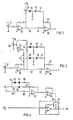
- FIG. 2 shows a simple circuit for the adapter.
- an operational amplifier connected as an IP controller is designated as a load state controller, e.g. B. serves as the above-mentioned W controller.
- the controller input is connected to the tap of a potentiometer 37 which is acted upon by the output signal of the drag controller 31 and on which the gain of the controller 30 can be adjusted.
- the controller output is connected via a line 33 and a resistor 35 to the input of a further operational amplifier 36.
- a voltage is applied to the controller output via a potentiometer 38, which voltage is selected to be positive if the inverting inputs of the operational amplifiers 30 and 36 are used to implement the circuit.
- the tap of the potentiometer 38 is connected via a series connection of a diode 39, a capacitor 40 and a resistor 41 to the input of the further operational amplifier 36 with the feedback resistor 42.
- the output of the diode leading to the capacitor 40 is advantageously grounded via a resistor.
- the frequency control variable f (the output of the W controller) is negative, with low frequencies corresponding to small values for f.
- the potentiometer 38 is set so that a slight positive voltage is present at the tap.
- the diode is switched in such a way that it blocks in this position, but becomes conductive as soon as the controller output signal becomes more negative at a higher frequency and the voltage tapped at the potentiometer 38 drops. Therefore, at low frequencies (blocked diode) this circuit has the gain determined by the ratio of the resistors 42 and 35, at higher frequencies (conductive diode) the gain is given by the ratio of the resistor 42 to the resistance formed by the parallel resistors 35 and 41.
- the point of use for the adaptation can be set on the potentiometer 38.
- the machine direction of rotation can be reversed by reversing the sign of the frequency control variable f.
- FIG. 2 is replaced by FIG. 3, in which the voltage tapped at the potentiometer 38 is also at the output of the regulator 30 via a voltage divider 44 and additionally by means of an inverter 43 and a corresponding voltage divider 44 '.
- the inverted potentiometer tap voltage is also applied to the input of the amplifier 36 via a diode 39 ', a capacitor 40' and a resistor 41 '.
- the load state variable W corresponds to the tangent of the load angle and, with a constant flow, the torque of the active current component (and thus also the actual W value).
- a Larger torque setpoint ie W * - W> 0
- the frequency, ie slip and load angle increase This means that the actual torque increases (as required) for load angles ⁇ 90 °, but decreases for load angles> 90 °. There is therefore a risk of tipping at load angles of around 90 °. If the load angle e (see Figure 5) is suddenly deflected from e.g. 70 ° to 110 ° due to an interference (e.g.
- the magnetization current i ⁇ 1 also calculated in the vector rotator 25 is added as soon as this current falls below a predetermined limit value S.
- the i ⁇ 1 output 45 of the actual value computer is connected to the variable tp at the divider input via a blocking circuit 46.
- a negative or at most a small positive value is advantageously chosen as the limit value, so that practically all positive i ⁇ 1 values are blocked, but negative values are added to ⁇ .
- the normal operating range (load angle below 90 °) is therefore not affected by this circuit; If, however, the load angle increases by more than 90 °, the denominator of the actual load state variable W is reduced, that is to say the actual W value is increased in a jerky manner. The frequency is therefore reduced via the load state controller until an angle is reached again in the normal operating range. This prevents the machine from tipping over. If, for example, the machine is to be operated up to a load angle of 80 °, the threshold is selected so that at a load angle of 110 ° the magnetizing current belonging to the maximum stator current is still blocked, but stronger negative magnetizing current values have an effect on the denominator of the actual W value . As a result, normal operation, in which the current vector oscillates at an average load angle of ⁇ 30 °, is not influenced by the blocking circuit, but at higher load angles the stator frequency is prevented from lowering.
- the magnetizing current i ⁇ 1 is also well suited for damping the load state control loop .
- the quotient i ⁇ 2 / ⁇ is a relatively slowly changing actual value due to the flow inertia. This can lead to vibrations.
- a damping effect on the load state control is achieved if the (more rapidly changing) actual value i ⁇ 1 is dynamically applied to the denominator of this quotient.
- the steady-state behavior of the control system should be unaffected, ie the actual magnetizing current value i ⁇ 1 is applied to the actual flux value ⁇ via a follower 47 at the input of the divider 14.
- Such a follow-up element is characterized by a strongly decaying step response function, ie the follow-up element responds to an abruptly increased input signal with a high positive, but rapidly decaying output signal. This avoids vibrations in the river.
- FIG. 4 shows a circuit arrangement for such a divider, the divisor input of which is preceded by such a blocking circuit and a follower.
- a voltage i ⁇ 1 tapped at the output 45 of the actual value computer causes a current in a line 52 leading via a resistor 50 to the input of an operational amplifier 51, which current is only passed through a correspondingly polarized diode 53 in the case of negative current values.
- a Zener diode 54 arranged in series with this also allows a current to flow only if the i ⁇ 1 values are below the threshold voltage.
- a capacitor 56 has the effect that a short charging current surge flows via line 55 and a resistor 57 to the amplifier input 51 only when the input voltage i ⁇ 1 changes.
- the voltage ⁇ tapped at the actual value computer leads in a further line 59 to a corresponding current flowing through the resistor 60 to the operational amplifier 51, so that there is a variable at the output of the amplifier 51 which corresponds to the variable im in the stationary case and at normal load angle , at load angle over 90 ° and / or with changes in the magnetizing current component i ⁇ 1, however, is modified in accordance with the above explanations.
- This output signal which may be inverted in an inverter 61 to produce the correct polarity, is fed to the divider input 62 of divider 14, the dividend input of which is acted upon by actual value i ⁇ 2 .
- switch 72 At low frequencies, the switch 72 is closed, at the same time the line coming from the comparison point 16 for the control deviation W * - W is opened via a switch 73.
- the switches 72 and 73 accordingly switch over from automatic stator frequency control to control of the stator frequency.
- switch 72 leads to the input of second W controller 30.
- Towing controller 31 is out of operation when switch 73 is open; If an operational amplifier is used as the following controller, its output can be short-circuited with the inverting input, so that the controller output is at zero.
- the function generator 11 specifies the setpoint i * only as a function of the ramp-up current in and does not react to fluctuations in the speed controller output variable i * ⁇ 2 .
- a smoothing element can advantageously be connected downstream of switch 74.
- the switch 73 can be designed as a changeover switch.
- the setpoint value i *, 2 supplied by the speed controller is adjusted to the actual value W calculated in the dividing element 14 in such a way that the difference W * - W disappears at the junction 16.
- both the speed controller 8 and the drag controller 31 have the position belonging to the vanishing control deviation and there is a smooth transition from the controlled to the regulated operating state.
Landscapes
- Power Engineering (AREA)
- Engineering & Computer Science (AREA)
- Control Of Ac Motors In General (AREA)
- Agricultural Chemicals And Associated Chemicals (AREA)
- Fats And Perfumes (AREA)
- Portable Nailing Machines And Staplers (AREA)
- Massaging Devices (AREA)
- Orthopedics, Nursing, And Contraception (AREA)
- Control Of Multiple Motors (AREA)
- Pharmaceuticals Containing Other Organic And Inorganic Compounds (AREA)
- Control Of Eletrric Generators (AREA)
- Vending Machines For Individual Products (AREA)
- Control Of Motors That Do Not Use Commutators (AREA)
- Extrusion Moulding Of Plastics Or The Like (AREA)
- General Details Of Gearings (AREA)
- Sorption Type Refrigeration Machines (AREA)
- Exchange Systems With Centralized Control (AREA)
Claims (12)
Priority Applications (1)
| Application Number | Priority Date | Filing Date | Title |
|---|---|---|---|
| AT80102301T ATE38598T1 (de) | 1979-05-16 | 1980-04-28 | Lastzustandsregelung einer umrichtergespeisten asynchronmaschine. |
Applications Claiming Priority (2)
| Application Number | Priority Date | Filing Date | Title |
|---|---|---|---|
| DE2919852 | 1979-05-16 | ||
| DE19792919852 DE2919852A1 (de) | 1979-05-16 | 1979-05-16 | Lastzustandsregelung einer umrichtergespeisten asynchronmaschine |
Publications (2)
| Publication Number | Publication Date |
|---|---|
| EP0019138A1 EP0019138A1 (fr) | 1980-11-26 |
| EP0019138B1 true EP0019138B1 (fr) | 1988-11-09 |
Family
ID=6070914
Family Applications (1)
| Application Number | Title | Priority Date | Filing Date |
|---|---|---|---|
| EP80102301A Expired EP0019138B1 (fr) | 1979-05-16 | 1980-04-28 | Dispositif de réglage de charge d'une machine asynchrone alimentée par un convertisseur |
Country Status (10)
| Country | Link |
|---|---|
| US (1) | US4338559A (fr) |
| EP (1) | EP0019138B1 (fr) |
| JP (1) | JPS55155594A (fr) |
| AT (1) | ATE38598T1 (fr) |
| CA (1) | CA1151724A (fr) |
| DE (2) | DE2919852A1 (fr) |
| DK (1) | DK210180A (fr) |
| FI (1) | FI71642C (fr) |
| IN (1) | IN152105B (fr) |
| NO (1) | NO153473C (fr) |
Cited By (1)
| Publication number | Priority date | Publication date | Assignee | Title |
|---|---|---|---|---|
| EP3462600A1 (fr) | 2017-09-29 | 2019-04-03 | Siemens Aktiengesellschaft | Machine asynchrone à efficacité énergétique |
Families Citing this family (37)
| Publication number | Priority date | Publication date | Assignee | Title |
|---|---|---|---|---|
| DE3112326A1 (de) * | 1981-03-28 | 1982-10-07 | Brown, Boveri & Cie Ag, 6800 Mannheim | Verfahren und vorrichtung zum erfassen des winkels zwischen dem luftspaltflussvektor und dem staenderstromvektor einer von einem stromzwischenkreis-umrichter gespeisten asynchronmaschine |
| DE3112325A1 (de) * | 1981-03-28 | 1982-10-07 | Brown, Boveri & Cie Ag, 6800 Mannheim | Vorrichtung zur regelung von drehzahl und/oder drehmoment einer asynchronmaschine mit i-zwischenkreis-umrichter |
| DE3114176A1 (de) * | 1981-04-03 | 1982-10-28 | Licentia Patent-Verwaltungs-Gmbh, 6000 Frankfurt | "schaltungsanordnung zur regelung eines zwischenkreisumrichters" |
| US4400655A (en) * | 1981-05-11 | 1983-08-23 | Imec Corporation | Self generative variable speed induction motor drive |
| CH644478A5 (fr) * | 1981-12-18 | 1984-07-31 | Cerac Inst Sa | Procede et moyens pour alimenter en energie electrique un outil portatif. |
| AT374597B (de) * | 1981-12-23 | 1984-05-10 | Siemens Ag Oesterreich | Schaltungsanordnung fuer eine abloesende regelung |
| US4431957A (en) * | 1981-12-29 | 1984-02-14 | General Electric Company | Method and apparatus for generating signals representing motor flux in an AC motor |
| DE3212439C2 (de) * | 1982-04-02 | 1992-02-20 | Robert Prof.Dr.-Ing. 6100 Darmstadt Jötten | Verfahren zum Betrieb einer durch schnelle elektrische Stellglieder gespeisten Asynchronmaschine |
| DE3232141A1 (de) * | 1982-08-26 | 1984-03-01 | Mannesmann AG, 4000 Düsseldorf | Anordnung zur regelung einer drehstrom-asynchronmaschine |
| JPS5963998A (ja) * | 1982-10-04 | 1984-04-11 | Hitachi Ltd | 誘導電動機の制御方法 |
| JPS59122392A (ja) * | 1982-12-27 | 1984-07-14 | Hitachi Ltd | 誘導電動機の制御装置 |
| DE3460506D1 (en) * | 1983-05-27 | 1986-09-25 | Siemens Ag | Method and apparatus to derive the flux vector of an induction machine from the stator current and the stator voltage, and application thereof |
| DE3341952A1 (de) * | 1983-11-21 | 1985-05-30 | Siemens AG, 1000 Berlin und 8000 München | Verfahren und vorrichtung zum betrieb einer ueber einen stromzwischenkreisumrichter gespeisten last, insbesondere einer asynchronmaschine, bei netzstoerung |
| DE3411572C2 (de) * | 1984-03-29 | 1986-12-04 | Joetten, Robert, Prof.Dr.-Ing., 6100 Darmstadt | Verfahren zur Regelung einer durch einen stromeinprägenden Zwischenkreisumrichter gespeisten Asynchronmaschine |
| DE3427841A1 (de) * | 1984-07-27 | 1986-02-06 | Siemens AG, 1000 Berlin und 8000 München | Verfahren und vorrichtung zum betrieb eines zwischenkreisumrichters mit stromanstiegsbegrenzung |
| DE3438504A1 (de) * | 1984-10-20 | 1986-04-24 | Brown, Boveri & Cie Ag, 6800 Mannheim | Verfahren und einrichtung zur regelung einer drehfeldmaschine |
| US4779709A (en) * | 1985-09-02 | 1988-10-25 | Hitachi, Ltd. | Apparatus for controlling AC elevators |
| US4698577A (en) * | 1986-01-16 | 1987-10-06 | General Electric Company | Method of digital flux reconstruction with DC elimination |
| US4677360A (en) * | 1986-03-13 | 1987-06-30 | General Electric Company | Field weakening induction drive |
| FI872593A (fi) * | 1986-08-18 | 1988-02-19 | Siemens Ag | Foerfarande och anordning foer att driva en faeltorienterad, med en styrbar omriktare matad vridfaeltmaskin. |
| US4740738A (en) * | 1986-09-17 | 1988-04-26 | Westinghouse Electric Corp. | Reluctance motor control system and method |
| JPH07108119B2 (ja) * | 1987-08-08 | 1995-11-15 | 三菱電機株式会社 | 誘導電動機制御装置 |
| FI885272A (fi) * | 1988-01-29 | 1989-07-30 | Siemens Ag | Foerfarande foer bildande av lastvinkel-nuvaerdet foer en faeltorienterad reglerad vridfaeltmaskin och motsvarande regleringsanordning. |
| FI885885A (fi) * | 1988-03-28 | 1989-09-29 | Siemens Ag | Anordning foer reglering av belastningsvinkel hos en stroemriktare. |
| US4870338A (en) * | 1988-09-26 | 1989-09-26 | Westinghouse Electric Corp. | Load commutated inverter (LCI) induction motor drive |
| US5196778A (en) * | 1989-06-23 | 1993-03-23 | Mitsubishi Denki Kabushiki Kaisha | Control apparatus suitable for use in induction motor |
| FI87413C (fi) * | 1989-11-20 | 1992-12-28 | Abb Stroemberg Drives Oy | Foerfarande foer foerhindrande av kippning av en asynkronmaskin |
| JP3064671B2 (ja) * | 1992-04-27 | 2000-07-12 | 富士電機株式会社 | 電力変換装置の制御回路 |
| JP3501559B2 (ja) * | 1995-06-27 | 2004-03-02 | キヤノン株式会社 | リニア・モータ装置 |
| DE19608039A1 (de) * | 1996-03-02 | 1997-09-04 | Bosch Gmbh Robert | Regelungsvorrichtung für eine Asynchronmaschine, insbesondere als Antrieb für Elektrofahrzeuge |
| FR2746982B1 (fr) * | 1996-03-28 | 1998-05-07 | Schneider Electric Sa | Convertisseur de frequence pour moteur alternatif |
| US6008618A (en) * | 1997-11-26 | 1999-12-28 | General Motors Corporation | Zero speed start-up for a speed sensorless induction motor drive |
| JP4654493B2 (ja) * | 2000-08-08 | 2011-03-23 | 株式会社安川電機 | 電動機制御装置 |
| FR2818826B1 (fr) * | 2000-12-27 | 2003-02-07 | Schneider Electric Ind Sa | Systeme de limitation du courant en sortie d'un variateur de vitesse |
| US7744366B2 (en) * | 2005-10-17 | 2010-06-29 | Thomas & Betts International, Inc. | System and method for improving the thermal efficiency of a heating system |
| DE102007058209B4 (de) * | 2007-12-04 | 2009-10-08 | Lenze Drives Gmbh | Verfahren zum Aufschalten eines Umrichters auf eine geberlos betriebene Asynchronmaschine |
| CN102844978A (zh) * | 2010-01-12 | 2012-12-26 | Mk控制股份有限公司 | 用于更高效运行异步电动机的方法和设备 |
Family Cites Families (4)
| Publication number | Priority date | Publication date | Assignee | Title |
|---|---|---|---|---|
| DE2106789C3 (de) * | 1971-02-12 | 1978-03-02 | Siemens Ag, 1000 Berlin Und 8000 Muenchen | Einrichtung zur Steuerung oder Regelung des Ständerstromvektors einer Asynchronmaschine |
| DE2234681C3 (de) * | 1972-07-14 | 1975-07-31 | Siemens Ag, 1000 Berlin Und 8000 Muenchen | Verfahren und Schaltungsanordnung zum Herabsetzen der Drehmomenten-Welligkeit einer Drehfeldmaschine |
| DE2635965C3 (de) * | 1976-08-10 | 1979-01-18 | Siemens Ag, 1000 Berlin Und 8000 Muenchen | Schaltungsanordnung und Verfahren zur Bildung einer elektrischen Größe, die einer Flußkomponente in einer Drehfeldmaschine proportional ist |
| US4215304A (en) * | 1978-10-02 | 1980-07-29 | General Electric Company | Motor/brake transitioning for an inverter driven a-c induction motor |
-
1979
- 1979-05-16 DE DE19792919852 patent/DE2919852A1/de not_active Withdrawn
-
1980
- 1980-03-13 IN IN286/CAL/80A patent/IN152105B/en unknown
- 1980-04-18 FI FI801248A patent/FI71642C/fi not_active IP Right Cessation
- 1980-04-28 DE DE8080102301T patent/DE3072129D1/de not_active Expired
- 1980-04-28 AT AT80102301T patent/ATE38598T1/de active
- 1980-04-28 EP EP80102301A patent/EP0019138B1/fr not_active Expired
- 1980-05-09 US US06/148,144 patent/US4338559A/en not_active Expired - Lifetime
- 1980-05-14 DK DK210180A patent/DK210180A/da unknown
- 1980-05-14 NO NO801455A patent/NO153473C/no unknown
- 1980-05-14 CA CA000351964A patent/CA1151724A/fr not_active Expired
- 1980-05-15 JP JP6466980A patent/JPS55155594A/ja active Pending
Non-Patent Citations (1)
| Title |
|---|
| Buch von D. Ernst und D. Ströle "Industrieelektronik" 1973, S. 204, * |
Cited By (3)
| Publication number | Priority date | Publication date | Assignee | Title |
|---|---|---|---|---|
| EP3462600A1 (fr) | 2017-09-29 | 2019-04-03 | Siemens Aktiengesellschaft | Machine asynchrone à efficacité énergétique |
| WO2019063419A1 (fr) | 2017-09-29 | 2019-04-04 | Siemens Aktiengesellschaft | Machine asynchrone à efficacité énergétique |
| US11283383B2 (en) | 2017-09-29 | 2022-03-22 | Siemens Aktiengesellschaft | Energy-efficient asynchronous machine |
Also Published As
| Publication number | Publication date |
|---|---|
| NO801455L (no) | 1980-11-17 |
| IN152105B (fr) | 1983-10-22 |
| JPS55155594A (en) | 1980-12-03 |
| DE2919852A1 (de) | 1980-12-04 |
| ATE38598T1 (de) | 1988-11-15 |
| FI71642B (fi) | 1986-10-10 |
| DK210180A (da) | 1980-11-17 |
| FI71642C (fi) | 1987-01-19 |
| DE3072129D1 (en) | 1988-12-15 |
| CA1151724A (fr) | 1983-08-09 |
| EP0019138A1 (fr) | 1980-11-26 |
| US4338559A (en) | 1982-07-06 |
| FI801248A (fi) | 1980-11-17 |
| NO153473C (no) | 1986-03-26 |
| NO153473B (no) | 1985-12-16 |
Similar Documents
| Publication | Publication Date | Title |
|---|---|---|
| EP0019138B1 (fr) | Dispositif de réglage de charge d'une machine asynchrone alimentée par un convertisseur | |
| DE2648150C2 (de) | Anordnung zur Steuerung der Drehzahl eines über einen Zwischenkreisumrichter gespeisten Asynchronmotors | |
| DE2833542C2 (de) | Drehfeldmaschinenantrieb, bestehend aus einer umrichtergespeisten Drehfeldmaschine, insbesondere Synchronmaschine und einer Stromrichtersteuerung für den eigengetakteten, insbesondere feldorientierten Betrieb dieser Maschine, mit zwei baugleichen Wechselspannungsintegratoren und Verfahren zum Betrieb des Drehfeldmajchinenantriebes | |
| EP0127158B1 (fr) | Procédé et appareillage pour la détermination du vecteur de flux d'une machine à champ tournant d'après le courant stator et la tension stator et utilisation de ceux-ci | |
| EP0043973A1 (fr) | Système d'entraînement d'une machine à champ tournant comportant une machine à champ tournant alimentée par l'intermédiaire d'un onduleur et une commande d'onduleur branchée à deux intégrateurs à tension alternative et au circuit d'un modèle de calcul | |
| DE2644748B2 (de) | Anordnung zur Regelung der Drehzahl einer Asynchronmaschine | |
| EP0161615B1 (fr) | Méthode et dispositif pour définir le vecteur de flux d'une machine à champ tournant | |
| DE19615199C2 (de) | Feldorientierte Steuerung für einen Induktionsmotor | |
| EP0674381B1 (fr) | Procédé de régulation du couple d'une machine asynchrone | |
| EP0633653B1 (fr) | Procédé de régulation de courant et dispositif pour un convertisseur de tension | |
| EP0007552A1 (fr) | Circuit pour la formation d'un signal à potentiel électrique qui est proportionnel à une composante de flux magnétique dans une machine à champ tournant | |
| DE3820125A1 (de) | Verfahren zum steuern eines elektromotores | |
| EP0161616A2 (fr) | Méthode et dispositif pour stabiliser le diagramme circulaire d'un vecteur formé par intégration | |
| DE3641278A1 (de) | Wechselrichter | |
| EP0771067A1 (fr) | Procédé et dispositif pour la régulation d'une machine à champ tournant, par l'orientation du champ | |
| DE4107362C2 (de) | Verfahren zum stoßfreien Zuschalten eines Umrichters auf eine sich mit unbekannter Drehzahl drehende Drehstromasynchronmaschine | |
| DE3144174A1 (de) | Vorrichtung zum feldorientierten betrieb einer drehfeldmaschine | |
| DE4209305C2 (de) | Verfahren und Einrichtung zur feldorientierten Regelung von Asynchronmaschinen | |
| DE3126277C2 (de) | Schaltungsanordnung zum Regeln des Ankerstromes eines Gleichstrommotors | |
| DE3149693A1 (de) | Regelvorrichtung fuer eine aus einem stromrichter gespeiste drehfeldmaschine | |
| EP0085338B1 (fr) | Dispositif pour déterminer la fréquence commune de deux valeurs alternatives indépendamment variables en particulier dans une machine à champ tournant | |
| DE2121693A1 (de) | Umkehrverstärkerstufe mit automatischer Nachstellung der Ansprechempfindlichkeit | |
| EP0015501B1 (fr) | Dispositif de démarrage pour le contrôle ou la régulation en champ orienté d'une machine asynchrone | |
| DE19752940A1 (de) | Verfahren und Vorrichtung zur dynamischen Leistungsregelung einer angetriebenen Synchronmaschine | |
| EP0171617B1 (fr) | Méthode et dispositif pour l'exploitation d'un convertisseur indirect avec limitation de la montée de courant |
Legal Events
| Date | Code | Title | Description |
|---|---|---|---|
| PUAI | Public reference made under article 153(3) epc to a published international application that has entered the european phase |
Free format text: ORIGINAL CODE: 0009012 |
|
| 17P | Request for examination filed | ||
| AK | Designated contracting states |
Designated state(s): AT BE CH DE FR GB IT NL SE |
|
| GRAA | (expected) grant |
Free format text: ORIGINAL CODE: 0009210 |
|
| AK | Designated contracting states |
Kind code of ref document: B1 Designated state(s): AT BE CH DE FR GB IT LI NL SE |
|
| REF | Corresponds to: |
Ref document number: 38598 Country of ref document: AT Date of ref document: 19881115 Kind code of ref document: T |
|
| REF | Corresponds to: |
Ref document number: 3072129 Country of ref document: DE Date of ref document: 19881215 |
|
| ET | Fr: translation filed | ||
| GBT | Gb: translation of ep patent filed (gb section 77(6)(a)/1977) | ||
| ITF | It: translation for a ep patent filed |
Owner name: STUDIO JAUMANN |
|
| PG25 | Lapsed in a contracting state [announced via postgrant information from national office to epo] |
Ref country code: GB Effective date: 19890428 Ref country code: AT Effective date: 19890428 |
|
| PG25 | Lapsed in a contracting state [announced via postgrant information from national office to epo] |
Ref country code: SE Effective date: 19890429 |
|
| ITTA | It: last paid annual fee | ||
| PG25 | Lapsed in a contracting state [announced via postgrant information from national office to epo] |
Ref country code: LI Effective date: 19890430 Ref country code: CH Effective date: 19890430 Ref country code: BE Effective date: 19890430 |
|
| PGFP | Annual fee paid to national office [announced via postgrant information from national office to epo] |
Ref country code: DE Payment date: 19890627 Year of fee payment: 10 |
|
| PLBE | No opposition filed within time limit |
Free format text: ORIGINAL CODE: 0009261 |
|
| STAA | Information on the status of an ep patent application or granted ep patent |
Free format text: STATUS: NO OPPOSITION FILED WITHIN TIME LIMIT |
|
| BERE | Be: lapsed |
Owner name: SIEMENS A.G. BERLIN UND MUNCHEN Effective date: 19890430 |
|
| PG25 | Lapsed in a contracting state [announced via postgrant information from national office to epo] |
Ref country code: NL Effective date: 19891101 |
|
| 26N | No opposition filed | ||
| NLV4 | Nl: lapsed or anulled due to non-payment of the annual fee | ||
| GBPC | Gb: european patent ceased through non-payment of renewal fee | ||
| PG25 | Lapsed in a contracting state [announced via postgrant information from national office to epo] |
Ref country code: FR Free format text: LAPSE BECAUSE OF NON-PAYMENT OF DUE FEES Effective date: 19891228 |
|
| REG | Reference to a national code |
Ref country code: CH Ref legal event code: PL |
|
| REG | Reference to a national code |
Ref country code: FR Ref legal event code: ST |
|
| PG25 | Lapsed in a contracting state [announced via postgrant information from national office to epo] |
Ref country code: DE Effective date: 19910101 |
|
| EUG | Se: european patent has lapsed |
Ref document number: 80102301.1 Effective date: 19900412 |