EP0017830B1 - Ofen zum Erwärmen von Brammen - Google Patents
Ofen zum Erwärmen von Brammen Download PDFInfo
- Publication number
- EP0017830B1 EP0017830B1 EP19800101690 EP80101690A EP0017830B1 EP 0017830 B1 EP0017830 B1 EP 0017830B1 EP 19800101690 EP19800101690 EP 19800101690 EP 80101690 A EP80101690 A EP 80101690A EP 0017830 B1 EP0017830 B1 EP 0017830B1
- Authority
- EP
- European Patent Office
- Prior art keywords
- cooled
- water
- skid
- posts
- heating furnace
- Prior art date
- Legal status (The legal status is an assumption and is not a legal conclusion. Google has not performed a legal analysis and makes no representation as to the accuracy of the status listed.)
- Expired
Links
Images


Classifications
-
- F—MECHANICAL ENGINEERING; LIGHTING; HEATING; WEAPONS; BLASTING
- F27—FURNACES; KILNS; OVENS; RETORTS
- F27B—FURNACES, KILNS, OVENS, OR RETORTS IN GENERAL; OPEN SINTERING OR LIKE APPARATUS
- F27B9/00—Furnaces through which the charge is moved mechanically, e.g. of tunnel type; Similar furnaces in which the charge moves by gravity
- F27B9/14—Furnaces through which the charge is moved mechanically, e.g. of tunnel type; Similar furnaces in which the charge moves by gravity characterised by the path of the charge during treatment; characterised by the means by which the charge is moved during treatment
- F27B9/20—Furnaces through which the charge is moved mechanically, e.g. of tunnel type; Similar furnaces in which the charge moves by gravity characterised by the path of the charge during treatment; characterised by the means by which the charge is moved during treatment the charge moving in a substantially straight path tunnel furnace
- F27B9/22—Furnaces through which the charge is moved mechanically, e.g. of tunnel type; Similar furnaces in which the charge moves by gravity characterised by the path of the charge during treatment; characterised by the means by which the charge is moved during treatment the charge moving in a substantially straight path tunnel furnace on rails, e.g. under the action of scrapers or pushers
-
- C—CHEMISTRY; METALLURGY
- C21—METALLURGY OF IRON
- C21D—MODIFYING THE PHYSICAL STRUCTURE OF FERROUS METALS; GENERAL DEVICES FOR HEAT TREATMENT OF FERROUS OR NON-FERROUS METALS OR ALLOYS; MAKING METAL MALLEABLE, e.g. BY DECARBURISATION OR TEMPERING
- C21D9/00—Heat treatment, e.g. annealing, hardening, quenching or tempering, adapted for particular articles; Furnaces therefor
- C21D9/0081—Heat treatment, e.g. annealing, hardening, quenching or tempering, adapted for particular articles; Furnaces therefor for slabs; for billets
-
- F—MECHANICAL ENGINEERING; LIGHTING; HEATING; WEAPONS; BLASTING
- F27—FURNACES; KILNS; OVENS; RETORTS
- F27B—FURNACES, KILNS, OVENS, OR RETORTS IN GENERAL; OPEN SINTERING OR LIKE APPARATUS
- F27B9/00—Furnaces through which the charge is moved mechanically, e.g. of tunnel type; Similar furnaces in which the charge moves by gravity
- F27B9/14—Furnaces through which the charge is moved mechanically, e.g. of tunnel type; Similar furnaces in which the charge moves by gravity characterised by the path of the charge during treatment; characterised by the means by which the charge is moved during treatment
- F27B9/20—Furnaces through which the charge is moved mechanically, e.g. of tunnel type; Similar furnaces in which the charge moves by gravity characterised by the path of the charge during treatment; characterised by the means by which the charge is moved during treatment the charge moving in a substantially straight path tunnel furnace
- F27B9/201—Furnaces through which the charge is moved mechanically, e.g. of tunnel type; Similar furnaces in which the charge moves by gravity characterised by the path of the charge during treatment; characterised by the means by which the charge is moved during treatment the charge moving in a substantially straight path tunnel furnace walking beam furnace
-
- F—MECHANICAL ENGINEERING; LIGHTING; HEATING; WEAPONS; BLASTING
- F27—FURNACES; KILNS; OVENS; RETORTS
- F27D—DETAILS OR ACCESSORIES OF FURNACES, KILNS, OVENS, OR RETORTS, IN SO FAR AS THEY ARE OF KINDS OCCURRING IN MORE THAN ONE KIND OF FURNACE
- F27D3/00—Charging; Discharging; Manipulation of charge
- F27D3/02—Skids or tracks for heavy objects
-
- C—CHEMISTRY; METALLURGY
- C21—METALLURGY OF IRON
- C21D—MODIFYING THE PHYSICAL STRUCTURE OF FERROUS METALS; GENERAL DEVICES FOR HEAT TREATMENT OF FERROUS OR NON-FERROUS METALS OR ALLOYS; MAKING METAL MALLEABLE, e.g. BY DECARBURISATION OR TEMPERING
- C21D8/00—Modifying the physical properties by deformation combined with, or followed by, heat treatment
- C21D8/12—Modifying the physical properties by deformation combined with, or followed by, heat treatment during manufacturing of articles with special electromagnetic properties
- C21D8/1205—Modifying the physical properties by deformation combined with, or followed by, heat treatment during manufacturing of articles with special electromagnetic properties involving a particular fabrication or treatment of ingot or slab
Definitions
- the present invention relates to a heating furnace, particularly a furnace for heating a steel prior to the hot working of the steel.
- the present invention relates, more particularly, to a walking beam type heating furnace and a pusher type heating furnace for heating the steel prior to the hot working of the steel, preferably an electromagnetic steel.
- the steel material is alternately placed on a group of stationary skid beams and a group of movable skid beams.
- the movable skid beams are moved in one cycle along the lifting, forward moving, lowering and returning paths, and thus forward the slabs in the walking beam type heating furnace.
- the movable skid beams being lifted receive the slabs on the stationary skid beams.
- the slabs are placed back on the stationary skid beams.
- the movable skid beams and the stationary skid beams which are immovable, are constructed by welding water- cooled metallic skids on water-cooled metallic tubes which extend in the longitudinal direction of the furnace, and by lining the entire outer circumference of the water-cooled metallic tubes with a refractory material layer.
- the water- cooled, metallic skids are spaced from each other by a predetermined gap.
- the water-cooled metallic tubes are supported by water-cooled posts, these posts being covered by a refractory material and protruding through the hearth of the walking beam type heating furnace.
- the water-cooled posts which support the stationary skid beams, stand vertically on the hearth and are stationary with respect to the hearth, while the water-cooled posts, which support the movable skid beams, protrude through slots in the hearth and are connected to a driving device located below the hearth.
- the hearth portions through which the posts supporting the movable beams protrude are provided with a bank formed on the hearth around each of these posts, so as to prevent the influx of molten slag or scale into the slots (c.f. Japanese Published Utility Model Applications Nos. 47-2739 and 49-15).
- the charging and discharging of slabs are performed by pushing the slabs from the charging side to the discharging side of the pusher type heating furnace.
- the heating zone of the furnace is provided with water cooled skid tubes to allow the slabs to be conveyed and suppprted.
- the slabs are pushed into contact with the refractory hearth, thereby allowing removal of so-called skid marks.
- the structure of the water-cooled metallic tubes, water-cooled posts and metallic skids of pusher type heating furnaces is the same as in the walking beam type heating furnaces. However, no gap is formed between the metallic skids in the pusher type heating furnace, because any gap acts as a resistance during the sliding movement of the steel sections, i.e. the steel slabs.
- the number of the above mentioned water- cooled posts of the walking beam and the pusher type heating furnaces is desirably as small as possible for the following reasons:
- the number of water-cooled posts is large, and further the heating temperature of the slabs is high, for example in the heating of electromagnetic steel, fuel consumption must be great enough to compensate for the heat withdrawal caused by the cooling water in the water-cooled posts.
- the heat insulating function of all of the water-cooled posts is increased so as to avoid high fuel consumption, the installation cost becomes very great.
- the number of water cooled posts should be as small as possible.
- Each of the driven water-cooled posts of the walking beam type heating furnaces protrudes through the slot mentioned above, and a water-cooled sealing box is fitted below the slot so as to prevent influx of the air through the slot into the interior of the walking beam type heating furnaces.
- the withdrawal of heat by the water in the water- cooled sealing box is more serious than that by the cooling water of the water-cooled posts.
- the known water-cooled posts' of the walking beam and pusher type heating furnaces are tubes which directly support the skid tubes. If the water-cooled posts are reduced to a certain number, the supporting force of the water-cooled posts is decreased correspondingly to the reduced number. It was believed in the art of slab heating furnaces that the force required for supporting the skid beams is provided by a certain number of the water- cooled posts, which number could not be reduced.
- the distance between a water- cooled post and an adjacent bank is small. This is because the number of the water-cooled posts is large, as explained above. Accumulation of molten slag or scale occurs at the space between the water-cooled post and the banks, with the result that the molten slag or scale overflows the banks into the slots. Accordingly, the walking beam type heating furnaces provided with the banks involve the problem of molten slag or scale accumulation, which should be eliminated.
- US-A-3 089 687 is described a walking beam furnace for moving work to be heated through the furnace.
- This furnace is so designed that the work supporting and moving members are periodically rotated so that they will be kept straight, and will wear evenly, thus prolonging their life and efficiency.
- US-A-3 345 050 discloses continuous or pusher type furnaces, in which steel slabs, blooms, billets, ingots, or other forms of metal articles are heated to rolling, forging or other desired temperature.
- One row, or more, of such articles is supported on water-cooled skid rails extending between the charging end of the furnace and a refractory soaking or discharge hearth located adjacent to the opposite end of the furnace.
- novel means are combined with the skid rails to arrest or diminish the thermal conductivity between such rails and the bodies of the articles supported thereby.
- the object of the DE-C-563976 is supporting pillars for cantlever pusher type heating furnace-skid tubes, characterized by a water-cooled post (a, i) supported on the furnace plate.
- the part of the post extending from the furnace bottom into the inner furnace is at its lower end surrounded by a loose, easily replaceable insulating material, e.g. sand, and at its upper part by a solid insulating substance, e.g. refractory stone which is supported by notches fixed at the post above the replaceable insulating material.
- the invention described in DE-B-1758 288 is related to a walking beam type heating furnace to perform heat treatment measures, especially on slabs and billets and similar with cooled stationary beams extending in the longitudinal direction of the furnace, and parallel to these cooled walking beams which are rigidly connected to a walking beam frame situated below the furnace bottom.
- a heating furnace according to the present invention comprises skid tubes of water-cooled skid beams and water-cooled posts for supporting the water-cooled skid beams, and is characterized in that
- the post head is provided with a trough-shaped receiving portion for a skid tube of a water-cooled skid beam and has a length greater than the outer diameter of the water- cooled post.
- the skid tubes of the water-cooled skid beams are metallic and cooling water flows through them.
- the skid tubes and the water cooled posts constitute continuous beams having a number of fulcrums.
- the cross section of the skid tubes is usually determined by the bending moment (M,) at each fulcrum.
- the present invention involves the concept of supplementing the force for supporting each of the skid tubes in the proximity of the fulcrums by means of the strength of each post head.
- the number of posts can be reduced to one half or less the number of posts having an outer diameter (d) equal to the length (I).
- the skid tubes and the water-cooled posts are provided with a covering of a refractory material resistant to the molten slag or scale at the outer circumference thereof.
- the skid tubes are mounted on one of the trough-shaped receiving portions with a highly heat-conductive material in between.
- the highly heat-conductive material may be compactly filled between the skid tubes and the trough-shaped receiving portions.
- the highly heat-conductive material is used in the present invention for the following reasons: In order to exert the cooling effect of the skid tubes on the post heads, and hence to protect the post heads by cooling, the skid tubes and the post heads are desirably in contact with each other. The heat conduction between the so contacted skid tubes and post heads would be high if a metallic contact were realized between them. However, it is in practice difficult to achieve a completely metallic contact between the skid tubes and the post heads due to the working accuracy of these tubes and post heads.
- Minute clearances are, therefore, locally formed between these tubes and post heads, and a heat-insulating layer is unavoidably formed due to gases in the clearances.
- the highly heat-conductive material is placed in between.
- the amount of the highly heat-conductive material compactly filled between the skid tubes and the trough-shaped receiving portions may be small. It is possible to effectively prevent a reduction of strength of the post heads because the cooling effect of the skid tubes satisfactorily extends to the post heads.
- a bracket is rigidly secured to the lower side of each of the skid tubes and extends in the longitudinal direction of the skid tubes, and the post head is connected to the bracket by means of a pin.
- the skid tubes can be readily exchanged by removing the pin from the bracket and the trough-shaped receiving portion and then withdrawing the skid tubes from the receiving portion.
- the pin-securing portion of the post head has a small thickness and is in the form of a thin neck.
- a highly heat-insulating refractory layer which is covered by the refractory covering at the outermost part of the water-cooled posts is formed on the neck portion.
- the thin neck portion is liable to have such a structure that it is difficult to accomodate therein a water cooling system.
- the structure of the neck portion is, therefore, not highly resistant to heat. Since the neck portion is thin, the thickness of the heat-insulating refractory layer is large. The thick and highly heat-insulating refractory layer can effectively protect the neck portion from a high- temperature heat in a heating furnace.
- the water-cooled posts are arranged in a zigzag pattern as seen in a plan view.
- a walking beam type heating furnace the water- cooled posts, the posts of the stationary skid beams and the posts of the movable skid beams, which are surrounded by banks for preventing the influx of molten slag or scale, are alternately arranged in a zigzag pattern.
- no water-cooled posts are positioned between the banks of the walking beam type heating furnace, and the distance between a water-cooled post and an adjacent bank is large. Consequently, the flowability of the molten slag or scale is considerably increased over the flowability in conventional walking beam type heating furnaces.
- the linear arrangement of the posts in conventional heating furnaces can also be adopted in the furnaces of the present invention.
- the zigzag arrangement is used in the walking beam type heating furnace as described above, the advantage of a small number of posts as well as the advantage of considerable enhancement of the flowability of the molten slag or scale on the hearth are achieved.
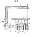
- a walking beam type heating furnace 1 illustrated in Figs. 1 and 2, the movable (driven) skid beams 2, 3, 4 and 5 and the stationary skid beams 6, 7, 8, 9 and 10 are arranged in parallel and alternately in the furnace 1, and run from a charging opening 11 to a discharging opening 12 of the furnace.
- axial flow burners are located on the furnace roof above the beams 2 through 10.
- Side burners 16 are located on the furnace side walls 13 and 14 below the beams 2 to 10 in such a manner that the axis 15 of the flame is horizontal.
- the side burners 16 are alternately positioned on the side wall 13 and the side wall 14.
- the axial flow burners and side burners are arranged in each of a preheating zone Za, a heating zone Zb and a soaking zone Zc.
- the hearth 18 is provided with extraction slots 21 for the molten slag or scale in both borders of the hearth along the side walls 13 and 14.
- the hearth 18 has gentle slopes which descend from the top at the center of the hearth to both borders along the side walls 13 and 14.
- the molten slag or scale, which falls down from the slab 17 to the hearth 18, is therefore caused to flow into the extraction slots 21.
- Slag or scale melting burners 23 located on the side walls enhance the flowability of the molten slag or scale on the hearth 18.
- the skid beams 2 to 10 are supported by water-cooled posts 19 and 24, which are described in detail below.
- a bank 30 is formed on the hearth 18 so that the inner wall of the bank 30 surrounds each of the slots 20 through which the water-cooled posts 19 for supporting the movable skid beams protrude.
- the banks 30 prevent the influx of the molten slag or scale into the slots 20.
- a beveled body 48 is rigidly secured to each of the water-cooled posts 19 and prevents the flow of the molten slag or scale along the posts 19 into the slots 20 and the dropping of the molten slag or scale directly into the slots 20.
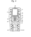
- FIGs. 3 and 4 the structure of the skid tubes and water-cooled posts is illustrated in detail.
- reference numeral 31 indicates a skid tube having a rectangular cross section and reference numeral 32 indicates a skid rail.
- a core tube 34 is accomodated in a water-cooled post 19 (24) to water-cool the post 19 (24).
- a metallic post head 35 is provided on the water-cooled post 19 (24) and supports the skid tubes 31.
- the post head 35 has a trough-shaped cross section and the length (I) of the trough-shaped post head is greater than the outer diameter (d) of the water- cooled posts 19 (24) which are made of metallic tubes.
- the number of water cooled posts is approximately one half of that in a walking beam type heating furnace where I is equal to d.
- the number of stationary skid beams is five and each of the stationary skid beams is supported by sixteen water-cooled posts.
- the total number of the water-cooled posts for supporting the stationary skid beams is, therefore, eighty.
- the number of movable skid beams is four and each of the movable skid beams is supported by sixteen water cooled posts which are driven so as to realize the movement of the movable skid beams.
- the total number of the driven water- cooled posts is, therefore, sixty-four.
- the number of water-cooled posts necessary for supporting one stationary skid beam of similar capacity to the particular furnace mentioned above is decreased from the sixteen mentioned above to nine.
- the number of water- cooled posts for supporting one movable skid beam is decreased from the sixteen mentioned above to eight.
- the total number of the water cooled posts is, therefore, decreased from 144 in the particular conventional walking beam type heating furnace mentioned above to 72 in the comparable furnace according to the present invention.
- a bracket 37 is fixed to the lower surface of the skid tube 31 along the longitudinal direction of the skid tube.
- a trough-shaped upper receiving portion 36 of the post head 35 is contiguous to a lower neck portion 40 thereof.
- the bracket 37 is secured to the post head by a pin connection through a positioning pin and a nut 38. Since the pin and nut are removable, the skid tubes 31 can be easily disassembled from the post head, if necessary.
- a highly heat-conductive material 39 for example SiC, is filled between the skid tube 31 and the inner surface of the post head 35.
- the skid tube 31 is welded to the circumference of the trough-shaped receiving portion 36 by a weld 41.
- a cooling effect extends from the skid tube 31 and water-cooled post 19 (24) to the post head 40.
- the cooling effect extended from the skid tube 31 and the water cooled post 19 (24) is least at the thin neck portion 40. Therefore, the thin neck portion 40 is subjected to external high temperature heat and is likely to lose its supporting function due to buckling. Consequently, a thick refractory layer 42, which is highly heat-insulating is formed on the neck portion 40.
- the refractory layer 42 may be ceramic fiber layers.
- Stainless sheets 43 are applied on the refractory layer 42.
- a refractory layer 46 covers all of the members of the skid tubes and the water cooled posts, so as to protect these members from the molten slag or scale which is generated by the melting of scale from the material being heated.
- the material of the refractory layer 46 is selected from such groups of materials as ceramic refractories which are not eroded by the molten slag or scale.
- the water cooled posts according to the present invention greatly contribute to the operation of a walking beam type heating furnace and rqduction of the heat withdrawal as compared with the prior art, because the load supporting system is realized by greatly increasing the distance between the fulcrums as compared with the prior art.
- the banks 30 and the posts 24 of stationary skid beams are arranged in a zigzag pattern, while the conventional skid beam arrangement pattern is linear, as seen in Fig. 5.
- the free space in between, having a distance (L) is large as compared to the free space in the arrangement in Fig. 5.
- the free space between an adjacent post and bank, having a distance (L') is also large.
- the operation of the furnace must be interrupted so as to withdraw the molten slag or scale from the furnace.
- the number of such interruptions of furnace operation is low. Consequently, compared to the prior art, in the present invention the heat loss due to interruption of the furnace operation is low and hence the degree by which the furnace is cooled is decreased. As a result, the amount of fuel necessary to heat the steel is less than in the prior art and, in addition, the maintenance costs involved in the withdrawal of the molten slag or scale from the furnace are low.
Landscapes
- Engineering & Computer Science (AREA)
- Mechanical Engineering (AREA)
- General Engineering & Computer Science (AREA)
- Chemical & Material Sciences (AREA)
- Physics & Mathematics (AREA)
- Thermal Sciences (AREA)
- Crystallography & Structural Chemistry (AREA)
- Materials Engineering (AREA)
- Metallurgy (AREA)
- Organic Chemistry (AREA)
- Heat Treatments In General, Especially Conveying And Cooling (AREA)
Claims (4)
Applications Claiming Priority (4)
| Application Number | Priority Date | Filing Date | Title |
|---|---|---|---|
| JP41819/79 | 1979-03-30 | ||
| JP38232/79 | 1979-03-30 | ||
| JP3823279A JPS55131119A (en) | 1979-03-30 | 1979-03-30 | Support structure of skid pipe in heating furnace |
| JP4181979U JPS55142562U (de) | 1979-03-30 | 1979-03-30 |
Publications (2)
| Publication Number | Publication Date |
|---|---|
| EP0017830A1 EP0017830A1 (de) | 1980-10-29 |
| EP0017830B1 true EP0017830B1 (de) | 1984-06-13 |
Family
ID=26377435
Family Applications (1)
| Application Number | Title | Priority Date | Filing Date |
|---|---|---|---|
| EP19800101690 Expired EP0017830B1 (de) | 1979-03-30 | 1980-03-28 | Ofen zum Erwärmen von Brammen |
Country Status (2)
| Country | Link |
|---|---|
| EP (1) | EP0017830B1 (de) |
| DE (1) | DE3068164D1 (de) |
Families Citing this family (3)
| Publication number | Priority date | Publication date | Assignee | Title |
|---|---|---|---|---|
| DE3705822A1 (de) * | 1987-02-24 | 1988-09-01 | Italimpianti Deutschland Gmbh | Hubbalkenofen |
| US4838785A (en) * | 1988-07-05 | 1989-06-13 | Cameron Forge Company | Walking beam furnace insulation |
| CN104818497B (zh) * | 2015-04-17 | 2017-05-10 | 郑州经纬科技实业有限公司 | 电解铝用阴极炭块预热装置及其使用方法 |
Family Cites Families (14)
| Publication number | Priority date | Publication date | Assignee | Title |
|---|---|---|---|---|
| DE563976C (de) * | 1932-11-12 | Ofenbau Ges M B H | Stuetzpfeiler fuer frei tragende Stossofen-Gleitrohre | |
| US2235771A (en) * | 1939-10-23 | 1941-03-18 | Surface Combustion Corp | Continuous heating furnace |
| US3089687A (en) * | 1960-11-18 | 1963-05-14 | Selas Corp Of America | Walking beam mechanism |
| AT223640B (de) * | 1961-02-21 | 1962-10-10 | Amsler Morton Industrieofenbau | Stoßofen |
| FR1325350A (fr) * | 1962-06-12 | 1963-04-26 | Brockmann & Bundt Ind Ofenbau | Système d'avancement pour fours à pas de pèlerin |
| US3220712A (en) * | 1961-08-29 | 1965-11-30 | Jack D Lott | Skid support construction |
| US3345050A (en) * | 1965-08-25 | 1967-10-03 | Loftus Engineering Corp | Furnace skid rails |
| US3567195A (en) * | 1967-06-26 | 1971-03-02 | Ishikawajima Harima Heavy Ind | Walking beam continuous heating furnace |
| US3471134A (en) * | 1968-02-26 | 1969-10-07 | Midland Ross Corp | Walking beam furnace |
| US3637198A (en) * | 1970-01-12 | 1972-01-25 | Koppers Wistra Ofenbau Gmbh | Furnace for heat treating of metallic workpieces |
| JPS5036846Y2 (de) * | 1971-01-27 | 1975-10-27 | ||
| JPS4915U (de) * | 1972-04-05 | 1974-01-05 | ||
| DE2705745C2 (de) * | 1977-02-11 | 1985-02-14 | Ruhrgas Ag, 4300 Essen | Gekühlter Tragbalken für Wärmöfen |
| DE2706711A1 (de) * | 1977-02-17 | 1978-08-24 | Koppers Wistra Ofenbau Gmbh | Gekuehlte tragkonstruktion fuer waermoefen und verfahren zur kuehlung der tragkonstruktion |
-
1980
- 1980-03-28 DE DE8080101690T patent/DE3068164D1/de not_active Expired
- 1980-03-28 EP EP19800101690 patent/EP0017830B1/de not_active Expired
Also Published As
| Publication number | Publication date |
|---|---|
| EP0017830A1 (de) | 1980-10-29 |
| DE3068164D1 (en) | 1984-07-19 |
Similar Documents
| Publication | Publication Date | Title |
|---|---|---|
| AU2006337956A2 (en) | Roller hearth furnace for heating and/or temperature equalization of steel or steel alloy continuously cast products and its arrangement upstream of a hot strip finishing train | |
| EP3390945B1 (de) | Palettenwagen zum transport von schüttgut für eine thermische behandlung und verfahren dafür | |
| US3749550A (en) | Walking beam furnace | |
| US6330269B1 (en) | Heat exchange pipe with extruded fins | |
| US4391587A (en) | Slab heating furnace | |
| EP0017830B1 (de) | Ofen zum Erwärmen von Brammen | |
| RU2281974C2 (ru) | Охлаждающий элемент для охлаждения металлургической печи | |
| KR101227382B1 (ko) | 용해 장치 | |
| US5800161A (en) | Heating and/or temperature-maintaining furnace for slabs | |
| US4330267A (en) | Kiln car | |
| US4218212A (en) | Refractory front wall for industrial furnace | |
| US3915441A (en) | Heating furnace of walking beam type | |
| KR101938583B1 (ko) | 가열로용 대차 | |
| GB1594167A (en) | Workpiece support systems for heat-treatment furnaces | |
| US4582482A (en) | Top-fired, walking hearth-type furnace | |
| JPS61231117A (ja) | 再熱炉 | |
| RU2802700C1 (ru) | Крышка промежуточного ковша | |
| RU214151U1 (ru) | Промежуточный ковш | |
| US4290752A (en) | Walking beam furnace | |
| CA1248349A (en) | Movable sill furnace for heating iron metallurgy products | |
| EP0059306A2 (de) | Hubbalkenofen | |
| KR101127937B1 (ko) | 가열로의 퇴적 스케일 균일화장치 | |
| GB2174985A (en) | Furnace sill cooling | |
| KR850000929B1 (ko) | 주철관의 열처리장치 | |
| US2508739A (en) | Multiple-layer hearth structure for metallurgical furnaces |
Legal Events
| Date | Code | Title | Description |
|---|---|---|---|
| PUAI | Public reference made under article 153(3) epc to a published international application that has entered the european phase |
Free format text: ORIGINAL CODE: 0009012 |
|
| 17P | Request for examination filed | ||
| AK | Designated contracting states |
Designated state(s): BE DE FR GB IT |
|
| ITF | It: translation for a ep patent filed |
Owner name: STUDIO TORTA SOCIETA' SEMPLICE |
|
| GRAA | (expected) grant |
Free format text: ORIGINAL CODE: 0009210 |
|
| AK | Designated contracting states |
Designated state(s): BE DE FR GB IT |
|
| REF | Corresponds to: |
Ref document number: 3068164 Country of ref document: DE Date of ref document: 19840719 |
|
| ET | Fr: translation filed | ||
| PLBE | No opposition filed within time limit |
Free format text: ORIGINAL CODE: 0009261 |
|
| STAA | Information on the status of an ep patent application or granted ep patent |
Free format text: STATUS: NO OPPOSITION FILED WITHIN TIME LIMIT |
|
| 26N | No opposition filed | ||
| BERE | Be: lapsed |
Owner name: NIPPON STEEL CORP. Effective date: 19880331 |
|
| PG25 | Lapsed in a contracting state [announced via postgrant information from national office to epo] |
Ref country code: GB Free format text: LAPSE BECAUSE OF NON-PAYMENT OF DUE FEES Effective date: 19881118 |
|
| GBPC | Gb: european patent ceased through non-payment of renewal fee | ||
| PG25 | Lapsed in a contracting state [announced via postgrant information from national office to epo] |
Ref country code: FR Free format text: LAPSE BECAUSE OF NON-PAYMENT OF DUE FEES Effective date: 19881130 |
|
| PG25 | Lapsed in a contracting state [announced via postgrant information from national office to epo] |
Ref country code: DE Effective date: 19881201 |
|
| REG | Reference to a national code |
Ref country code: FR Ref legal event code: ST |
|
| PG25 | Lapsed in a contracting state [announced via postgrant information from national office to epo] |
Ref country code: BE Effective date: 19890331 |